Table of Contents
Advertisement
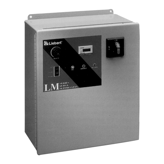
LIEBERT LM SERIES SURGE PROTECTIVE DEVICE
INSTALLATION, OPERATION AND MAINTENANCE MANUAL
UNPACKING AND INSTALLATION....................................................................................... 2
Unpacking and Preliminary Inspection............................................................................. 2
Handling Considerations .................................................................................................... 2
Storage.................................................................................................................................. 2
Location Considerations ..................................................................................................... 2
Door Closing Adjustments.................................................................................................. 2
ELECTRICAL CONNECTIONS .............................................................................................. 5
Voltage Rating & Source Configurations ......................................................................... 5
Parallel Connection............................................................................................................. 5
System Grounding & Bonding ........................................................................................... 9
OPERATION .............................................................................................................................. 10
TROUBLESHOOTING / REPAIR / MAINTENANCE........................................................... 12
Red LED on Door Illuminated & Green LED on Door Extinguished ........................... 12
Display Blank - No Red or Green LEDs Illuminated on Door...................................... 12
Preventative Maintenance (Inspection and Cleaning)................................................... 13
LIMITED WARRANTY.............................................................................................................. 14
DECLARATION OF CONFORMITY....................................................................................... 16
FIGURE
Figure 1. Cabinet Data, Form C Contact and Wiring .................................................... 3
Figure 2. Voltage Ratings and Power Source Configurations..................................... 6
Figure 3. Typical Parallel Connections (without External Disconnect Switch) ......... 8
Figure 4. Typical Parallel Connections (with External Disconnect Switch) ............... 8
Figure 5. Remote Monitor Panel...................................................................................... 11
Installation, Operation
and Maintenance Manual
®
TABLE OF CONTENTS
- 1 -
Surge
Suppression
Systems
LM Series
Rev 0, 5/99
Advertisement
Table of Contents

Subscribe to Our Youtube Channel
Related Manuals for Liebert LM Series


Summary of Contents for Liebert LM Series
-
Page 1: Table Of Contents
Surge ® Suppression Systems LIEBERT LM SERIES SURGE PROTECTIVE DEVICE INSTALLATION, OPERATION AND MAINTENANCE MANUAL TABLE OF CONTENTS UNPACKING AND INSTALLATION..................2 Unpacking and Preliminary Inspection................2 Handling Considerations ....................2 Storage..........................2 Location Considerations ..................... 2 Door Closing Adjustments....................2 ELECTRICAL CONNECTIONS .................... - Page 2 TRANSIENT VOLTAGE SURGE SUPPRESSION NSTALLATION LM Series PERATION AINTENANCE ANUAL Liebert...
- Page 3 ©1999 Liebert Corporation All rights reserved throughout the world. support. Specifications subject to change without notice. ®Liebert and the Liebert logo are registered trademarks of Liebert Corporation. Printed in U.S.A SL-22030 (5/99)
-
Page 4: Unpacking And Installation
Systems INSTALLATION INSTRUCTIONS FOR THE LIEBERT LM SERIES SURGE PROTECTIVE DEVICE The Liebert LM Series Surge Protective Device is a high The installer should perform the following steps to assure a quality, high energy surge current diversion system designed quality installation. The entire installation manual should be to protect sensitive equipment from damaging transient read before starting installation. - Page 5 LM & LM1 Series Models with No Options (Wt. 15 lbs.) LM & LM1 Series Models with Options (Wt. 16 lbs.) Figure 1. Cabinet Data, Form C Contact and Wiring Installation, Operation - 3 - LM Series and Maintenance Manual Rev 0, 5/99...
- Page 6 Surge ® Suppression Systems LM, LM1, & LM2 Series Models with Options (Wt. 35 lbs.) Figure 1. Cabinet Data, Form C Contact and Wiring Installation, Operation - 4 - LM Series and Maintenance Manual Rev 0, 5/99...
-
Page 7: Electrical Connections
#8 AWG wire must be utilized to connect the Disconnect Switch – SPD units must be connected to the LM series to your facilities’ power grid. Connections load side of the service disconnect, or load side of a made with conductors other that #8 AWG may result in protected circuit’s disconnecting means. - Page 8 Three Phase Delta Hi Leg, 4 W + G Figure 2. Voltage Ratings and Power Source Configurations * Replacement part numbers shown are for LM1 and LM2 Series only. Please contact factory for LM Series replacement part numbers. Installation, Operation...
- Page 9 LM (1 OR 2) 600Y420 M600Y420 No Neutral Figure 2. Voltage Ratings and Power Source Configurations * Replacement part numbers shown are for LM1 and LM2 Series only. Please contact factory for LM Series replacement part numbers. Installation, Operation - 7 - LM Series...
- Page 10 *If neutral is provided, a reliable neutral must be pulled to the SPD unit. Figure 4. Typical Parallel Connections (with External Disconnect Switch) *If neutral is provided, a reliable neutral must be pulled to the SPD unit. Installation, Operation - 8 - LM Series and Maintenance Manual Rev 0, 5/99...
-
Page 11: System Grounding & Bonding
The use of isolating bushings or other means to interrupt violation (reference NEC 250-51 and 250-54), and is not a metallic conduit run is a potential safety hazard and is recommended. not recommended. Installation, Operation - 9 - LM Series and Maintenance Manual Rev 0, 5/99... -
Page 12: Operation
Systems OPERATION Summary Alarm Contact – Summary alarm Form C (1 Liebert SPD Systems require little or no operator intervention after installation. N.O. and 1 N.C.) relay contacts are provided for remote indication of each failed surge current diverter module/s. - Page 13 500 feet away from the power cord with a NEMA 5-15 plug for connection to a LM Series Surge Protection System. Operation of the 120 VAC source. Control connections are required from Remote Monitor Panel is similar to the unit system the remote monitor panel to the power supply board in monitor panel.
-
Page 14: Troubleshooting / Repair / Maintenance
Remove customer wiring (or wiring from disconnect to module, if disconnect is provided) identifying which color supply wire goes where for re-wiring purposes (i.e., red supply wire removed from Phase B, etc…). Installation, Operation - 12 - LM Series and Maintenance Manual Rev 0, 5/99... -
Page 15: Replacing Power Supply Board Units With Counter Or Audible Alarm Options
Inspections for failed surge current diverter modules using available diagnostics should be done routinely (weekly or monthly). Installation, Operation - 13 - LM Series and Maintenance Manual Rev 0, 5/99... -
Page 16: Limited Warranty
This Warranty sets forth our responsibilities in the unlikely event of defect and tells you how to obtain performance under this Warranty. FIVE YEAR LIMITED WARRANTY AGAINST DEFECTS IN MATERIAL AND WORKMANSHIP CONTROL CONCEPTS PRODUCTS COVERED: LM Series Surge Suppression Products. Terms of Warranty: As provided herein, the Control Concepts product is warranted to be free of defects in material and workmanship for a period of five (5) years from the date of delivery of the product to User. - Page 17 This Warranty represents the entire agreement between Control Concepts and User with respect to the subject matter herein and supersedes all prior or contemporaneous oral or written communications, representations, understandings or agreements relating to this subject. Installation, Operation - 15 - LM Series and Maintenance Manual Rev 0, 5/99...
-
Page 18: Declaration Of Conformity
Systems DECLARATION OF CONFORMITY All models of the LM Series Surge Protective Devices are in compliance with the EMC Directive 89/336/EEC, conforming to EMC standard IEC 1000-4-4 and IEC 1000-4-5. ----- Office of the Vice-President of Engineering, Binghamton, NY USA, April 1998.
Need help?
Do you have a question about the LM Series and is the answer not in the manual?
Questions and answers