Table of Contents
Advertisement
Advertisement
Table of Contents
Troubleshooting

Related Manuals for BBK DV214SI(RU)


Summary of Contents for BBK DV214SI(RU)
- Page 1 DV214SI(RU) service manual VerSI09.10...
-
Page 2: Table Of Contents
Catalog Chapter One About Maintenance 1.1 Safety precautions 1.1.1 Power supply 1.1.2 Precautions for antistatic 1.1.3 Precautions for laser head 1.1.4 About placement position 1.2 Maintenance method 1.2.1 Visualized method 1.2.2 Electric resistance method 1.2.3 Voltage method 1.2.4 Current method 1.2.5 Cutting method 1.2.6 Element substitution method 1.2.7 Comparison method... - Page 3 2.4.6 Karaoke settings menu 2.4.7 Preference settings 2.4.8 Parental Control 2.4.9 Initial setup menu 2.4.10 Reset to defaults 2.4.11 Exit setting menu 2.4.12 Channel delay set-up 2.5 MISCELLANEOUS 2.5.1 Useful notes 2.5.2 Trouble shooting 2.5.3Specification Chapter Three Block Diagram 3.1 OVERALL WIRING DIAGRAM FOR PLAYER 3.2 BLOCK DIAGRAM FOR PLAYER Chapter Four Block Diagram of Unit Circuit 4.1 Servo Circuit...
- Page 4 7.8 Surface layer of OK Board (DV214&216SI-MIC.PCB V2.0) 7.9 Bottom layer of OK Board (DV214&216SI-MIC.PCB V2.0) Chapter Eight Circuit Diagram 8.1 Decode Board (SKY_CX2:03 2009.07.20) 8.2 AV Board (SCART-OUT 2006.12.25) 8.3 Power Board (SKY-P00904A) 8.4 Main Panel (DV214&216SI.PCB V2.0) 8.5 OK Board (DV214&216SI-MIC.PCB) 8.6 USB Board (DV214&216SI.PCB-V2.0) Chapter Nine BOM List...
- Page 5 Caution : This service manual is only applicable to DV214SI(RU) SI09.10...
-
Page 6: Chapter One About Maintenance
Chapter One About Maintenance 1.1 Safety precautions 1.1.1 Power supply When maintenance personnel are repairing DVD players, he should pay special attention to power board with 220V AC and 330V DC which will cause hurt and damage to persons! 1.1.2 Precautions for antistatic Movement and friction will both bring static electricity which causes serious damages to integrated IC. -
Page 7: About Placement Position
1.1.4 About placement position 1. Never place DVD player in positions with high temperature and humidity. 2. Avoid placing near high magnetic fields, such as loudspeaker or magnet. 3. Positions for placement should be stable and secure. 1.2 Maintenance method 1.2.1 Visualized method Directly view whether abnormalities of collision, lack of element, joint welding, shedding welding, rosin joint, copper foil turning up, lead wire disconnection and elements burning up among pins of... -
Page 8: Element Substitution Method
1.2.6 Element substitution method When some elements cannot be judged good or bad, substitution method may de adopted directly. 1.2.7 Comparison method A same good PC board is usually used to test the correct voltage and waveform. Compared these data with those tested through fault PC board, the cause of troubles may be found. Through the above maintenance method, theoretical knowledge and maintenance experience, all difficulties and troubles will be readily solved. -
Page 9: Chapter Two Functions And Operation Instructions
Chapter Two Functions and Operation Instructions 2.1 Features Compatible Disc Types #Digital video playback: DVD-video, super VCD, VCD compatibility #MPEG-4 standard support: compatibility with DivX3.11, DivX4, DivX5, DivX Pro, XviD compressed video files #Digital audio playback: CD(CD-DA)and HDCD compatibility #Fully compatible with compressed audio files such as MP3,WMA and OGG Vorbis formats #Playback of DVD-Video, VCD, CD+G Karaoke discs #Digital graphic albums playback: Kodak picture CD, JPEG compatibility Audio... -
Page 10: Controls And Functions
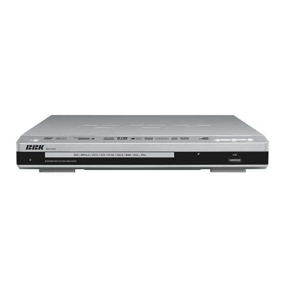
2.2 Controls and functions 2.2.1 Front and side panels control POWER button(Press to switch ON/OFF Microphone input STOP button(Press to stop the playback) the device) PLAY/PAUSE button(Press to OPEN/CLOSE button(Press to open/close playback/pause) the disc tray) Disc tray The indicator of operating mode/Standby mode USB port Phones jack Sensor of infrared beams... -
Page 11: Led Display General View(No Display For Dv214Si
2.2.3 LED display general view Playback time 2.2.4 Remote Control general view Button Press to open / close the disc tray. LANG Button Press to change the language MEM button Press to memorize the point where playback was stopped/playback from the previously memorized point. -
Page 12: Set List
2.3 Set list TV system AUTO DVD player 1PCS TV scan mode Video output. S-Vid. Audio cord 1PCS TV format 4:3 LB Video cord 1PCS Sharpness Med. High Gamma Medium Off. Remote control 1PCS Brightness Contrast Battery AAA 2PCS 1PCS Warranty card Saturation User’s manual... -
Page 13: Image Settings Menu
2.4.3 Image settings menu #Upon completion press the LEFT key of the UP and DOWN buttons to return to image setup 1.TV system: TV system selection menu. #Options: Auto, PAL, NTSC. 2.4.4 Sound settings menu #Default option: PAL. 2.TV scan mode: scan mode Selection Options: progressive, interlaced. -
Page 14: Playback Settings
#Default option: Off. G. PRO Logic ll: function of stereo sound C. Echo: echo effects. conversion to 5-channel sound. #Options: Off, Concert, Living room, Hall, #Options: On, Off, Auto. Bathroom, Cave, Arena, Church. #Default option: Auto. #Default option: Off. #In Auto position, the DVD player determines D. -
Page 15: Karaoke Settings Menu
3.Files:selection of reproduced files on the disc 2.4.7 Preference settings #Options: Audio, Picture, Video. 1.Gr. Equalizer: spectrum analyzer #Default option: A, P, V #Options: On, Off. 4. Repeat : file repeat mode #Default option: Off. #Options: Off, Single, All. 3.Screensaver:screen saver on/off #Default option: Off. -
Page 16: Exit Setting Menu
Load factory settings Cancel Optimum 2.4.11 Exit setting menu Admissable Distance to front speakers(inches) Not recommended Select the exit item using the Up and Down buttons and press the OK to exit the menu. Fig.2.Detemine delay value as to Dolby Pro Logic mode Language Image Sound... - Page 17 whisper etc. have merely disappeared. To avoid this, you just have to decrease the volume of “loud” sounds by simultaneously increasing the volume of “soft” sounds with the volume of “average” sounds left unchanged, i.e. Just decrease the dynamic range of sound Fig.2.Small area Delay accompaniment.
-
Page 18: Miscellaneous
Poss ibility of programmable cont rol of the decoder to t ransfer bass es int o low- Compatible with exist iing and future two- Miscellaneous frequency c hannel in systems equipped channel(s tereo) formats . with broad-band speakers and a subwoofer. -
Page 19: 3Specification
1.Remote control is incorrec tly direct ed 1.Use t he remote c ontrol ac cording at the DV D players's sc reen. to the m anual. Remote control does not 2. Distance to the DV D players is in 2.Decreas e the dis tance to the DV D operate excess of 8 meters. -
Page 20: Chapter Three Block Diagram
Chapter Three Block Diagram 3.1 OVERALL WIRING DIAGRAM FOR PLAYER Overall wiring diagram of DV214&216SI(RU) player is shown in figure 3.1.1. POWER BOA RD SKY-00904A 800-904A01-0 CN602 DV214&216SI-POWER.PCB V2.0 LOAD- LOAD- LOAD+ LOAD+ TROUT TROUT TRIN TRIN LIMIT LIMIT USB_DM USB_DM USB_DP USB_DP... -
Page 21: Block Diagram For Player
3.2 BLOCK DIAGRAM FOR PLAYER Block diagram for DV214&216SI(RU) player is shown in figure 3.2.1. Audio Amplify Filter URST ASPDIF SY_B/U SC_R/V Video VEDST CVBS Filter G/Y1# VEDCK B/PB# CVBS Clamping R/PR# VEDAT MIC1 MIC_IN1 Figure 3.2.1 Block diagram of DV214&216SI(RU) - 16 -... -
Page 22: Chapter Four Block Diagram Of Unit Circuit
Chapter Four Block Diagram of Unit Circuit 4.1 Servo Circuit Servo system of this machine adopts SONY loader and MTK decode scheme. And servo circuit is mainly composed of front signal processing, digital servo processing, digital signal processing chip MT1389 and driving chip AM5888. MT1389 is also main part of decode circuit. Block diagram of servo circuit is shown in figure 4.1.1. -
Page 23: Decode Circuit
4.2 Decode Circuit Decode circuit is mainly composed of MT1389,SDRAM and FLASH. Block diagram of circuit is shown in figure 4.2.1. SDCLK SF_CS SDCKE SF_DO FLASH SF_DI DRAS SF_CK SDRAM MT 1389L DQM0 DQM1 URST Reset Circuit DQ0~DQ15 MA0~MA11 DV33 1.8V 3.3V voltage... -
Page 24: Audio Circuit
4.4 Audio Circuit Block diagram for audio circuit is shown in figure 4.4.1 SPDIF ASPDIF IEC958 OPTICAL SCRAT 4558 Audio 4558 terminal MT1389 4558 Filter MIC_IN1 MIC B Mute circuit oard Circuit Figure 4.4.1 Block diagram of audio circuit 4.5 Power Circuit 1.Block diagram of power circuit is shown in figure 4.5.1. -
Page 25: Chapter Five Troubleshooting Flow Chart
Chapter Five Troubleshooting Flow Chart Machine power on Check whether Replace power wire and voltage of two sides of trouble is removed power wire is 90~250V Check Check whether whether insurance two sides of power Replace insurance tube board CE5 tube is normal is 300V Check rectifying diode... - Page 26 Check whether elements Check power supply around oscillator are normal, Replace FLASH circuit of decode board replace oscillator if it is OK Check Check whether USB Check whether 5V voltage whether USB terminal voltage is normal, replace MT1389 reading is is normal chip if it is normal available...
- Page 27 Check Check Check whether power Check whether mute whether pin 1 of 4558 whether sound output supply of pin 4, 8 of 4558 circuit is normal has sound is normal is normal output Check power supply Whether circuit of power board C22 capacitance has Replace MT1389 chip sound output...
-
Page 28: Chapter Six Waveform Diagram
Chapter Six Waveform Diagram This section collects signal waveform diagram of audio, video and each unit circuit with the purpose to help servicing personnel to judge where trouble lies in accurately and quickly to improve servicing skills. For the difference of oscillograph's type, model and tuner, a certain difference may exist, so the servicing personnel are expected to pay more attention to check in daily operation. - Page 29 3. Waveform diagram for feed signal FMO(when pick up has feed motion). Vpp=13.4V 4.Waveform diagram for traction signal TRO(when pick up has traction motion). Vpp=4.2V 5.Waveform diagram for focus signal FOO(when pick up has focus motion). Vpp=5.1V - 24 -...
- Page 30 6.Waveform diagram for FLASH chip SF_DI(pin 5 of U5). Vpp=4.08V 7.Waveform diagram for FLASH chip SF_CK(pin 6 of U5). Vpp=3.40V 8.Waveform diagram for 27MHz clock (X1). Vpp=1.12V - 25 -...
- Page 31 9. Reset signal URST waveform diagram. 10. Video signal waveform diagram. 11. 1KHZ audio signaal output waveform diagram(it is suggested to use test disc,if not,waveform tested will change at any time,which will affect your judgment). Vpp=4.60V - 26 -...
-
Page 32: Chapter Seven Pcb Board
Chapter Seven PCB Board 7.1 Surface layer of Decode Board(SKY_CX2:03 2009.07.20) - 27 -... -
Page 33: Surface Layer Of Av Board
7.2 Surface layer of AV Board(DV214&216SI) 7.3 Bottom layer of AV Board(DV214&216SI) 7.4 Power Board (SKY-P00904A ) - 28 -... -
Page 34: Surface Layer Of Main Panel
7.5 Surface layer of Main Panel (DV214&216SI.PCB V2.0) 7.6 Bottom layer of Main Panel (DV214&216SI.PCB V2.0) 7.7 USB Board (DV214&216SI.PCB V2.0) - 29 -... -
Page 35: Surface Layer Of Ok Board
7.8 Surface layer of OK Board (DV625SI-MIC.PCB V2.0) 7.9 Bottom layer of OK Board (DV625SI-MIC.PCB V2.0) - 30 -... -
Page 36: Chapter Eight Circuit Diagram
Chapter Eight Circuit Diagram 8.1 Decode Board(SKY_CX2:03 2009.07.20) - 31 -... - Page 37 - 32 -...
- Page 38 - 33 -...
-
Page 39: Av Board (Scart-Out 2006.12.25)
- 34 -... -
Page 40: Power Board (Sky-P00904A)
8.3 Power Board (SKY-P00904A) - 35 -... -
Page 41: Main Panel (Dv214&216Si.pcb V2.0)
8.4 Main Panel (DV214&216SI.PCB V2.0) - 36 -... -
Page 42: Ok Board (Dv214&216Si-Mic.pcb)
8.5 OK Board (6DV51 1SI-2)4940956 - 37 -... -
Page 43: Usb Board (Dv214&216Si.pcb-V2.0)
8.6 USB Board ( DV214&216SI.PCB V2.0SI-0) - 38 -... - Page 44 DVD PLAYER DV214SI SILVER(RU MTK1389DE-L(2.1CH+USB+Scart+Coaxial+S- Video+Video+ DivX3,4,5,6,Xvid Mpeg4+Firmware) SERIA MATERIAL CODE MATERIAL NAME SPECIFICATIONS UNIT QUANTITY LOCATION NUMB & & PLASTIC COMPONENTS 803-214S03-0 OF FRONT PANEL BOM LIST VERSION NO.: SI09.10 1.1. DV214SI SILVER USB&MIC&KEY BOARD 832-214S04-0 SERIA MATERIAL CODE MATERIAL NAME SPECIFICATIONS UNIT QUANTITY...
- Page 45 1.1.20 191-048250-26 FLAT CABLE 4PIN 26# 2.0MM L=250MM FRONT PANEL 1.1.21 191-046220-23 FLAT CABLE 4PIN 22#/28# 2.0MM L=220MM USB BOARD 1.1.22 191-036210-52 FLAT CABLE A3PIN(2.0MM),B2PIN(2.54MM) L= PCS MIC BOARD 1.2. DV214SI SILVER POWER KEY BOARD 832-214S16-0 SERIA MATERIAL CODE MATERIAL NAME SPECIFICATIONS UNIT QUANTITY LOCATION...
- Page 46 POWER CABLE 2.17 281-088801-0 L=125MM W=10MM' BANDING WIRE KNOT 2.18 501-250805-10 RUBBER EVA90 L25*8MM*5MM(25*8) LOADER 2.19 502-140040-11 SPRRONG CUSHION EVA90 φ14MM*4MM BUTTOM CABINET 2.20 501-170808-12 SPRRONG CUSHION EVA90 L17*W8*H6MM FRONT PANEL DOUBLE-FACE YELLOW 2.21 551-318S01-0 150MM (9M/R 9MM) ADHESIVE TAPE 2.23 533-080310-0 RED PAD...
- Page 47 C52/53/55/59/60/63/79/80/8 3.27 100nF 16V ±20% 0402 023-104042-00 CHIP CAPACITOR 3.28 1UF 16V ±20% 0603 C161,C165,C168 023-105042-10 CHIP CAPACITOR 3.29 023-475022-10 4.7UF 6.3V ±20% 0603 C58,C43,C24 CHIP CAPACITOR 3.30 (PZ2012U121) FB120R/0805 L2,L4,L5,L22, 085-121R25-2 CHIP BEAD L3,L6,L7,L9,L10,L13,L15,L1 3.31 085-121R25-1 CHIP BEAD 3.32 100uH 0805 ±10% L8,L14 005-101100-1...
- Page 48 3.69 MT1389DE-L/SMD LQFP-128 033-1389DE-1 3.70 033-AM5888-0 3.71 内存IC : HY57V641620FTP-6(现代) 033-641620-3 3.72 EON F16-100HCP 033-000F16-1 3.73 NJM4558 / SOP-8 033-004558-0 3.74 JHX 27.000MHz 137-270000-30 CRYSTAL OSCILLATOR 3.75 190-0CX202-02 SKY-CX2:02 2009.6.25 7.5*7.71CM PCS 4. DV214SI SILVER LOADER COMPONENTS 820-030801-01 SERIA MATERIAL CODE MATERIAL NAME SPECIFICATIONS UNIT QUANTITY...
- Page 49 3.69 MT1389DE-L/SMD LQFP-128 033-1389DE-1 3.70 033-AM5888-0 3.71 内存IC : HY57V641620FTP-6(现代) 033-641620-3 3.72 EON F16-100HCP 033-000F16-1 3.73 NJM4558 / SOP-8 033-004558-0 3.74 JHX 27.000MHz 137-270000-30 CRYSTAL OSCILLATOR 3.75 190-0CX202-02 SKY-CX2:02 2009.6.25 7.5*7.71CM PCS 4. DV214SI SILVER LOADER COMPONENTS 820-030801-01 SERIA MATERIAL CODE MATERIAL NAME SPECIFICATIONS UNIT QUANTITY...
- Page 50 ,D611 5.21 127-106052-1 ELECTROLYTIC CAPACIT 10uF/25V ±20% 5*11mm 105℃ C604 5.22 127-107052-1 ELECTROLYTIC CAPACIT 100uF/25V ±20% Φ6.3*12MM 105℃ PCS C609,C610 5.23 127-158042-0 ELECTROLYTIC CAPACIT 1500uF 16V ±20% 105℃ (Φ10*21m PCS C606 5.24 127-477042-0 ELECTROLYTIC CAPACIT 470uF/16V ±20% 8*12mm -40+105℃ PCS C612 5.25 127-475402-0...
- Page 51 6.25 602-214S01-00 GIFT BOX 328*78*260MM 6.26 604-214S01-00 SHIPPING BOX 654*343*280MM 0.16667 6.28 601-0RBK02-00 PE BAG 185*278MM 0.04MM 6.29 601-082740-01 PE BAG 80*270MM*0.04MM 7. DV214SI SILVER SCART BOARD 832-0RBK27-1 SERIA MATERIAL CODE MATERIAL NAME SPECIFICATIONS UNIT QUANTITY LOCATION NUMB SCART+YUV+OPTICAL 832-0RBK27-1 SCART+YUV+OPTICAL+COAXIAL SET OUTPUT BOARD H PCS...
Need help?
Do you have a question about the DV214SI(RU) and is the answer not in the manual?
Questions and answers