Advertisement

DV311SI DV313SI
DV314SI DV315SI
service manual

Advertisement

Table of Contents
loading
Need help?

Need help?

Do you have a question about the DV311SI and is the answer not in the manual?

Questions and answers

Саша
April 30, 2025

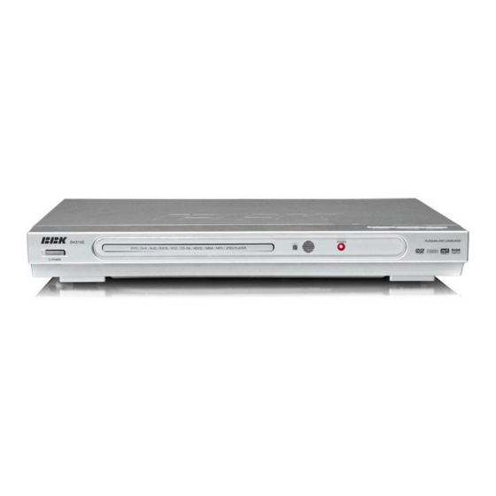
Здравствуйте у меня не работает дисплей на двд мне нужно чтобы он показал время сколько идёт фильм или песня и так далее как то включал раньше на пульте две кнопки и дисплей включался и выключался а щас. за помогите пожалуйста Эксплуатация BBK DV 311SI вот его название

User image 6811bab6ad11c

Summary of Contents for BBK DV311SI

  • Page 1 DV311SI DV313SI DV314SI DV315SI service manual...
  • Page 2 Catalog Chapter One About Maintenance 1.1 Safety precautions 1.1.1 Power supply 1.1.2 Precautions for antistatic 1.1.3 Precautions for laser head 1.1.4 About placement position 1.2 Maintenance method 1.2.1 Visualized method 1.2.2 Electric resistance method 1.2.3 Voltage method 1.2.4 Current method 1.2.5 Cutting method 1.2.6 Element substitution method 1.2.7 Comparison method...
  • Page 3 2.4.6 Karaoke 2.4.7 Preference 2.4.8 Parental Control 2.4.9 Initial setup 2.4.10 Rest to defaults 2.4.11 Exit 2.5 Specifications Chapter Three Principle and Servicing Section one principle of the player 3.1.1 Block diagram of the player 3.1.2 PCB board composition figure and video signal figure Section Two Unit Circuit Principle 3.2.1 Introduction to laser head 3.2.2 Servo Circuit...
  • Page 4: Table Of Contents

    3.5.2 function introduction to 4558 3.5.3 function introduction to AT24C02 3.5.4 function introduction to VIPer22ADIP 3.5.5 function introduction to AM5888S 3.5.6 function introduction to PT6961(4dv315) 3.5.7 Function introduction to SDRAM 3.5.8 Function introduction to FLASH 3.5.9 Function introduction to LM431A 3.5.10 Function introduction to Pc817 Chapter Four Disassembly and Assembly Process Chapter Cinque PCB board &...
  • Page 5 DV315SI Service Manual 9.1.1 Features 9.2.1 PCB board block diagram of the player 9.3.1 Servicing cases 9.3.2 Troubleshooting flow chart 9.4.1 PCB board 9.4.2 Circuit diagram...
  • Page 6: Chapter One About Maintenance

    Chapter One About Maintenance 1.1 Safety precautions 1.1.1 Power supply When maintenance personnel are repairing DVD players, he should pay special attention to power board with 220V AC and 330V DC which will cause hurt and damage to persons! 1.1.2 Precautions for antistatic Movement and friction will both bring static electricity which causes serious damages to integrated IC.
  • Page 7: About Placement Position

    1.1.4 About placement position 1. Never place DVD player in positions with high temperature and humidity. 2. Avoid placing near high magnetic fields, such as loudspeaker or magnet. 3. Positions for placement should be stable and secure. 1.2 Maintenance method 1.2.1 Visualized method Directly view whether abnormalities of collision, lack of element, joint welding, shedding welding, rosin joint, copper foil turning up, lead wire disconnection and elements burning up among pins of...
  • Page 8: Element Substitution Method

    1.2.6 Element substitution method When some elements cannot be judged good or bad, substitution method may de adopted directly. 1.2.7 Comparison method A same good PC board is usually used to test the correct voltage and waveform. Compared these data with those tested through fault PC board, the cause of troubles may be found. Through the above maintenance method, theoretical knowledge and maintenance experience, all difficulties and troubles will be readily solved.
  • Page 55: Section Five Function Introduction To Ic

    Section Five Function Introduction to IC 3.5.1 function introduction to MT1389E 1. DESCRIPTION MT1389E is a cost-effective DVD system-on-chip (SOC) which incorporates advanced features like MPEG-4 video decoder, high quality TV encoder and state-of-art de-interlace processing. Based on MediaTek’ s world-leading DVD player SOC architecture, the MT1389E is the 3rd generation of the DVD player SOC.
  • Page 56 Versatile video scaling & quality enhancement OSD & Sub-picture Built-in clock generator Built-in high quality TV encoder Built-in progressive video processor Audio effect post-processor Built-in 5.1-ch Audio DAC Built-in 2-ch Audio ADC for Karaoke (2)High Performance Analog RF Amplifier Programmable fc Dual automatic laser power control Defect and blank detection RF level signal generator...
  • Page 57 Supports 5/3.3-Volt. FLASH interface Supports power-down mode Supports additional serial port (7)DVD-ROM/CD-ROM Decoding Logic High-speed ECC logic capable of correcting one error per each P-codeword or Q-codeword Automatic sector Mode and Form detection Automatic sector Header verification Decoder Error Notification Interrupt that signals various decoder errors Provide error correction acceleration (8)Buffer Memory Controller Supports 16Mb/32Mb/64Mb SDRAM...
  • Page 58 High Definition Compatible Digital (HDCD) Windows Media Audio (WMA) Dolby ProLogic II Concurrent multi-channel and downmix out IEC 60958/61937 output PCM / bit stream / mute mode Custom IEC latency up to 2 frames Pink noise and white noise generator Karaoke functions Microphone echo Microphone tone control...
  • Page 59 4. PIN DESCRIPTION Main Type Description RF interface (26) RFGND18 Ground Analog ground RFVDD Power Analog power 1.8V Analog output RF Offset cancellation capacitor connecting Analog output RF Offset cancellation capacitor connecting RFGC Analog output RF AGC loop capacitor connecting for DVD-ROM Current reference input.
  • Page 60 LDO2 Analog output Laser driver output LDO1 Analog output Laser driver output Reference voltage (3) V2REFO Analog output Reference voltage 2.8V Analog output Reference voltage 2.0V VREFO Analog output Reference voltage 1.4V Analog monitor output (7) SVDD3 Power Analog power 3.3V Central servo RFOP Analog output...
  • Page 61 LPFIN Analog input Negative input terminal of loop filter amplifier LPFOP Analog output Positive output of loop filter amplifier Motor and Actuator Driver Interface (10) OP_OUT Analog output Op amp output OP_INN Analog input Op amp negative input OP_INP Analog input Op amp positive input Analog output Disk motor control output.
  • Page 62 SRPU InOut 4~16mA, HIGHA1 Microcontroller address 9 SRPU InOut 4~16mA, HIGHA2 Microcontroller address 10 SRPU InOut 4~16mA, HIGHA3 Microcontroller address 11 SRPU InOut 4~16mA, HIGHA4 Microcontroller address 12 SRPU InOut 4~16mA, HIGHA5 Microcontroller address 13 SRPU InOut 4~16mA, HIGHA6 Microcontroller address 14 SRPU InOut 4~16mA, HIGHA7...
  • Page 63 SRPU InOut 4~16mA, IOA 3 Microcontroller address 3/ IO SRPU InOut 4~16mA, IOA 4 Microcontroller address 4/ IO SRPU InOut 4~16mA, IOA 5 Microcontroller address 5/ IO SRPU InOut 4~16mA, IOA 6 Microcontroller address 6/ IO SRPU InOut 4~16mA, IOA 7 Microcontroller address 7/ IO SRPU InOut 4~16mA,...
  • Page 64 SRPD,SMT InOut 4mA, Microcontroller read strobe, active low URD# SRPD,SMT InOut 4~16mA, Microcontroller port 1-2 UP1_2 SRPD,SMT InOut 4mA, Microcontroller port 1-3 UP1_3 SRPD,SMT InOut 4mA, Microcontroller port 1-4 UP1_4 SRPD,SMT InOut 4mA, Microcontroller port 1-5 UP1_5 SRPD,SMT InOut 4mA, 9) Microcontroller port 1-6 UP1_6 SRPD,SMT...
  • Page 65 4) Audio bit clock YUV0 InOut 4mA, 5) While internal audio DAC used: ABCK GPIO I) Digital video YUV output 0 II) GPIO 6) Audio DAC master clock YUV0 InOut 4mA, 7) While internal audio DAC used: ACLK GPIO I) Alternate digital video YUV output 0 II) GPIO 8) Audio serial data 0 (Front-Left/Front-Right) 9) Trap value in power-on reset:...
  • Page 66 I) Microcontroller external interrupt 2 II) Digital video YUV output 0 III) GPIO Output SPDIF 4~16mA, S/PDIF output SR: ON/OFF AADVSS Ground Ground pin for 2ch audio ADC circuitry AKIN2 Analog Audio ADC input 2 ADVCM Analog 2ch audio ADC reference voltage AKIN1 Analog Audio ADC input 1...
  • Page 67 ADACVDD2 Power 3.3V power pin for audio DAC circuitry Video Interface (12) DACVDDC Power 3.3V power pin for video DAC circuitry VREF Analog Bandgap reference voltage Analog Full scale adjustment DACVSSC Ground Ground pin for video DAC circuitry InOut 4mA, CVBS Analog composite output DACVDDB...
  • Page 68 SPDATA 43) Microcontroller external interrupt 1 44) Audio S/PDIF SPDATA input 45) General purpose IO 4 GPIO4 SPLRCK InOut 2mA 46) Audio S/PDIF SPLRCK input 47) General purpose IO 5 INT3# GPIO5 InOut 2mA 48) Microcontroller external interrupt 3 SPBCK 49) Audio S/PDIF SPBCK input InOut 4mA, 50) General purpose IO 6...
  • Page 69 DQM1 InOut Data mask 1 InOut DRAM data 8 InOut DRAM data 9 RD10 InOut DRAM data 10 RD11 InOut DRAM data 11 RD12 InOut DRAM data 12 RD13 InOut DRAM data 13 RD14 InOut DRAM data 14 RD15 InOut DRAM data 15 InOut DRAM data 0...
  • Page 70 ◆ Low Power Consumption ◆ No Latch-Up ◆ Unity-Gain Bandwidth . . . 3 MHz Typ ◆ Gain and Phase Match Between Amplifiers ◆ Low Noise . . . 8 nV? H z Typ at 1 kHz ◆ Designed To Be Interchangeable With ◆...
  • Page 71: Function Introduction To Viper22Adip

    ◆ 2-wire Serial Interface ◆ Schmitt Trigger, Filtered Inputs for Noise Suppression ◆ Bi-directional Data Transfer Protocol ◆ 100 kHz (1.8V) and 400 kHz (2.5V, 2.7V, 5V) Compatibility ◆ Write Protect Pin for Hardware Data Protection ◆ 8-byte Page (1K, 2K), Write Modes ◆...
  • Page 72 – Overvoltage protection in hiccup mode. 2. FEATURES ◆ FIXED 60 KHZ SWITCHING FREQUENCY ◆ 9V TO 38V WIDE RANGE VDD VOLTAGE ◆ CURRENT MODE CONTROL ◆ AUXILIARY UNDERVOLTAGE LOCKOUT WITH HYSTERESIS ◆ HIGH VOLTAGE START UP CURRENT SOURCE ◆ OVERTEMPERATURE, OVERCURRENT AND OVERVOLTAGE PROTECTION WITH AUTORESTART 3.
  • Page 73 4) Level shift circuit built-in. 5) Thermal shut down circuit built-in. 6) Mute mode built-in. 7) Dual actuator drivers: A general purpose input OP provides differential input for signal addition. The output structure is two power OPAMPS in bridge configuration. 8) Sled motor driver:A general purpose input OP provides differential input for signal addition.
  • Page 74: Function Introduction To Pt6961(4Dv315)

    VCTL Speed control input of tray driver Ground VINLD Input for spindle driver No Connection TRB_2 Connect to external transistor base VINTK Input for tracking driver BIAS Input for reference voltage MUTE Input for mute control 3.5.6 function introduction to PT6961(4dv315) 1.
  • Page 75: Function Introduction To Sdram

    Key data input Key data input Power supply SG1/KS1 Segment output SG2/KS2 Segment output SG3/KS3 Segment output SG4/KS4 Segment output SG5/KS5 Segment output SG6/KS6 Segment output SG7/KS7 Segment output SG8/KS8 Segment output SG9/KS9 Segment output SG10/KS10 Segment output SG11 Segment output SG12/GR7 Segment output Grid output...
  • Page 76 Name Function Signal flow Name Function Signal flow     3.3V power supply Ground Data bus Address bus VDDQ 3.3V power supply Address bus Data bus Address bus Data bus Address bus   VSSQ Ground Address bus Data bus Address bus Data bus MA11 Address bus...
  • Page 77: Function Introduction To Flash

    3.5.8 Function introduction to FLASH FLASH (U214) is a 16Mbit FLASH memorizer, and the damage of U214 may cause troubles, such as power not on, no disc reading and power on picture mosaic. Pin function is shown as the following table: Name Function Voltage (when no disc)
  • Page 78 3.5.10 Function introduction to Pc817 U502 (2501) is a photoelectric coupler, shown as the figure 3.5.10.1. The right side is a light emitting diode, which sends out light of different intensity according to the strength of voltage inputted from the right side, generates photocurrent of different intensity on the left side according to light of different intensity, and outputs from position D.
  • Page 80: Chapter Cinque Pcb Board & Circuit Diagram

    Chapter Cinque PCB board & Circuit diagram Section One PCB board 5.1.1 Surface layer of AV OUT Board V703 L713 L714 L701 L702 L703 L704 JP701 R706 V701 V702 XS702 XS706 - 75 -...
  • Page 81 5.1.2 Bottom layer of AV OUT Board ZD702 ZD701 R711 C725 C726 ZD704 ZD703 R715 C716 R712 C724 C723 - 76 -...
  • Page 82 5.1.3 Surface layer of DECODE&SERVO Board - 77 -...
  • Page 83 5.1.4 Bottom layer of DECODE&SERVO Board - 78 -...
  • Page 84 5.1.5 MIC Board R612 TC616 C602 XS602 R607 TC613 R632 TC605 U601 JP601 R633 TC603 XS601 R619 C619 TC615 C601 6311SA-0 TANG DVD 2006/03/08 Q601 - 79 -...
  • Page 85 5.1.6 KEY SCAN Board C405 R402 R401 TC407 R417 LED403 LED401 H=5.5MM R415 K401 K403 D401 K402 U403 JP402 R406 Q401 LED402 XS401 4141-0 LEI 2004.05.07 R407 R418 R416 - 80 -...
  • Page 86: Power Board

    5.1.7 POWER Board BC501 C515 R501 T1.6AL 250V R512 R505 F501 TC502 TC512 U502 JP502 JP504 C504 TC513 D506 D513 G502 D511 +3.3V BC503 R511 L501 TC506 U501 ZD502 BCN503 D501 D502 L503 TC510 C503 CN502 D504 D503 R517 R503 TC505 AC 220V IN JP501...
  • Page 87 MIC_DET R265 330R MIC_IN1 R266 OKA# MIC_IN2 R267 OKA# C297 C298 C299 R271 R205 R2111 30K 36K(NC) C2111 150pF +A9V R2117 R2123 4.7K R2135 89_AR CH-R 89V33 TC240 TC246 C2117 10uF/16V R2136 ZD203 10uF/1206 U209B -A9V R2147 3V/0.5W 4580 XS205 100K C2129 C292...
  • Page 88 AVCC DACVDD3 89V33 R308 R309 L206 APLLVDD3 89V33 R215 100K FBSMT L205 JITFO C219 391 JITFN 100K L316 4.7uH 89V33 LDO-AV33 FBSMT L201 R311 RFV18 C243 FBSMT C242 TC212 TC211 C241 C318 C319 1.8V R209 750K 10uF/16V Q305 C230 L219 X201 C231 C232...
  • Page 89 U208 SDRAM 64M 89V33 D214 89V33 1N4148*2 JK702 C254 U202 VGND AT24C02 SDCKE R232 L705 R233 GREEN L225 DC/NC 1.8uH RST_/NC RST/WP R/Cr R/Cr# VIDEO_SY C705 WP/RST_ C295 20pF R246 C283 VIDEO_R/V C284 L706 47pF MA10 DQ10 47pF A10/AP DQ10 MA11 DQ11 BLACK...
  • Page 90 R706 +10V V701 R714 8050 R709 PDAT1 330R 2.2K RGB_CVBS R715 C727 C716 R705 R704 R708 4.7K AGND R710 PDAT0 V702 8050 2.2K C723 C726 C725 AGND JK706 L713 FCM XS706 AGND A(B)OUT XS16 A(B)IN PDAT2 A(A)OUT L714 FCM PDAT1 A-COM SPDIF RETURN...
  • Page 91 U403 HS0038A2 C405 R416 R417 R418 4.7K 4.7K 4.7K TC407 R415 100uF/16V R406 K401 LED401 R401 K402 R407 Q401 K403 8050 LED402 R402 LED403 D401 IN4148 XS401 XS07...
  • Page 92 TC601 L602 4.7U R603 MIC601 560R CK3-6.35-24 C612 R601 R605 5.1K R633 R632 10R1/6W 10R1/6W +9VA -9VA L603 TC615 C601 TC616 C602 FBSMT 100U/16V 100U/16V R620 5.1K XS602 XS601 C609 R621 R609 R613 C605 -9VA C607 XS601 TC605 R607 47U/16V TC603 TC613 R612...
  • Page 93 L505 10uH/1A D508 HER105 R503 C502 D503 TC503 TC504 D502 103/1KV C508 39K/2W 1N4007 470uF/16V 470uF/16V 1N4007 T501 D501 D504 C503 TC501 D505 D510 L507 10uH/2A 1N4007 101/1KV SR560 47uF/400V HER107 1N4007 TC505 TC506 C510 1000uF/10V 1000uF/10V +3.3V D509 D513 1N4007 1N4007 TC510...
  • Page 94 Chapter six BOM List MATERIAL MATERIAL NAME SPECIFICATIONS LOCATION CODE DV311SI(RU)SILVER[1389E] OUTPUT BOARD 5448370 0000273 CARBON FILM RESISTOR 1/4W33O±5% SHAPED 10 R708 0000278 CARBON FILM RESISTOR 1/4W330O±5% SHAPED 10 R709 2100004 LEAD F 0.6 SHAPED 10mm R706 0700007 SMD DIODE 1N4148 D701,D702    ①...
  • Page 95 MATERIAL MATERIAL NAME SPECIFICATIONS LOCATION CODE 0090181 SMD RESISTOR 1/16W 100O±5% 0603 R702 0090008 SMD RESISTOR 1/16W 220O±5% R701 0090009 SMD RESISTOR 1/16W 330O±5% 0603 R340,R377,R315,R265 0090249 SMD RESISTOR 1/16W 510O±5% 0603 R228 0090012 SMD RESISTOR 1/16W 560O±5% 0603 R206 R207,R232,R233,R274,R278,R2135~R 0090014 SMD RESISTOR 1/16W 1K±5% 0603...
  • Page 96 MATERIAL MATERIAL NAME SPECIFICATIONS LOCATION CODE C205,C207~C209,C211,C214,C216,C2 17,C225,C227~C232,C236,C239,C241~ C243,C249,C250,C254,C260,C262~C2 0310207 SMD CAPACITOR 50V104±20% 0603 65,C279,C281,C301~C306,C313,C316~ C319,C2140~C2142,C710,C711 ③ C205,C207~C209,C211,C214,C216,C2 17,C225,C227~C232,C236,C239,C241~ C243,C249,C250,C254,C260,C262~C2 0310543 SMD CAPACITOR 50V 104±10% X7R 0603 65,C279,C281,C301~C306,C313,C316~ C319,C2140~C2142,C710,C711 ③ 0310234 SMD CAPACITOR 16V 105 +80%-20% 0603 C201~C204,C292,C2154~C2159 0310066 SMD CAPACITOR 50V 102±10% 0603 C224,C299,C705,C706,C2117,C2118 0310067 SMD CAPACITOR...
  • Page 97 1910253 TERMINAL SOCKET AV3-8.4-5G-5 JK702 24P 0.5mm SMD SUBMIT MEET WITH 1940094 CABLE SOCKET XS301 CLASP 1633108 PCB 2314SI-0 DV311SI(RU)SILVER[1389E] MAIN PANEL 5448375 5232805 SOFT SPONGE SPACER 6×6×2.5 DOUBLE-FACED,HARD 0000276 CARBON FILM RESISTOR 1/4W100O±5% SHAPED 10 R415 0570006 DIODE 1N4148 D401 1340003 LIGHT TOUCH RESTORE SWITCH HORIZONTAL 6×6×1...
  • Page 98 MATERIAL MATERIAL NAME SPECIFICATIONS LOCATION CODE 1563163 PCB 4141-0 DV311SI(RU)SILVER[1389E] OK(2) BOARD 5448376 0000294 CARBON FILM RESISTOR 1/4W10K±5% SHAPED 10 R605 0000299 CARBON FILM RESISTOR 1/4W22K±5% SHAPED 10 R601 0000280 CARBON FILM RESISTOR 1/4W560O±5% SHAPED 10 R603 0000290 CARBON FILM RESISTOR 1/4W5.1K±5% SHAPED 10...
  • Page 99 2P 8.0mm 2# BCN501,BCN502 1940022 SOCKET 4P 2.0mm CN502 0881933 IC VIPER22A DIP8 U501 3870115 GROUND CHIP OF POWER BOARD AB903 G501,G502 DV311SI(RU)SILVER[1389E] REMOTE CONEROL 5471656 0310048 SMD CAPACITOR 50V 151±5% NPO 0603 C802,C803 0630009 EMISSION PIPE TSAL4400 LED801 0700007 SMD DIODE 1N4148 D801~D803    ⑨...
  • Page 100 RC026 3850125 CATHODE SPRING RC026 3850126 ANODE/CATHODE SPRING RC026 CONDUCT GLUE OF REMOTE 4631052 RC026-01R 4# CONTROL 5070070 GLUE BAG 85×250 DV311SI(RU)SILVER[1389E] PROGRAM FLASH ROMDV311SIRU-0A(16M) 0911700 0881650 IC 29LV160BE-70PFTN TSOP U207 0881651 IC M29W160EB 70N6 TSOP U207 - 95 -...
  • Page 106: Pcb Board

    7.5.1 PCB board 1. KEY SCAN Board - 101 -...
  • Page 107 TC403 100uF/16V XS401 C401 L401 R407 R416 R417 R418 MIC601 560R CK3-6.35-24 4.7K 4.7K 4.7K C404 R408 R406 5.1K K401 OPEN/CLOSE L403 K402 PLAY/PAUSE FBSMT R409 5.1K K403 STOP C405 R410 在 上 从 左 到 右 放 置 U403 HS0038A2 C408 R109 1...
  • Page 113: Pcb Board

    8.5.1 PCB board 1. Surface layer of KEY SCAN Board LED401 K403 K402 K401 MIC401 U402 TC402 TC403 R405 TC404 4314SI-0 DVD 2006/04/03 XS401 XS402 - 108 -...
  • Page 114 2. Bottom layer of KEY SCAN Board C403 L401 VD401 R406 C404 C402 R408 C405 R407 U401 R410 R409 C401 R401 - 109 -...
  • Page 115 U401 LED401 R401 TC403 DOUT LEDAT 100uF/16V LEDCK LEDST KEY1 XS401 KEY2 LEDST XS06 R402 KEY3 R403 LEDCK LEDAT R404 LED-SOCK(1) SEG1/KS1 SEG2/KS2 SEG12/GR7 C401 SEG3/KS3 SEG11 SEG10/KS10 SEG4/KS4 SEG9/KS9 SEG5/KS5 SEG8/KS8 AGND XS402 SEG6/KS6 SEG7/KS7 MICIN XS03 PT6961 TC402 C402 100uF/16V R409...
  • Page 120: Pcb Board

    9.4.1 PCB board 1. KEY SCAN Board - 115 -...
  • Page 121 U401 LED401 R401 TC402 DOUT LEDAT 100uF/16V LEDCK LEDST KEY1 XS401 KEY2 LEDST XS06 R403 KEY3 LEDCK R404 R405 LEDAT LED-SOCK(1) SEG1/KS1 SEG2/KS2 SEG12/GR7 C401 SEG3/KS3 SEG11 SEG10/KS10 SEG4/KS4 SEG9/KS9 SEG5/KS5 SEG8/KS8 SEG6/KS6 SEG7/KS7 PT6961 TC401 C402 100uF/16V U402 HS0038B VD401 1N4148 C403...

This manual is also suitable for:

Dv313siDv314siDv315si

Table of Contents