Table of Contents
Advertisement
Operation
™
™
X5
, X7
, ProX7
Airless Sprayers
- For portable spray applications of architectural paints and coatings -
Models 262800, 262805, 261815, 261820
See page 2 for model and series information including
dispense rate, recommended hose length, guns, and
maximum working pressure.
IMPORTANT SAFETY INSTRUCTIONS.
Read all warnings and instructions in this
manual. Save these instructions.
C.J. Spray, Inc.
6270 Claude Way E
Inver Grove Heights, MN 55076
1-888-CJSPRAY
(888-257-7729)
™
& ProX9
M
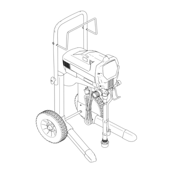
X5
AGNUM
Model: 262800
Series D
ti11304a
M
X7
AGNUM
Model: 262805
Series C
ti11305a
The manual provided with
TM
this sprayer contains
English and Español.
Visit our website;
http://M
™
X5 & X7 Models ONLY: Use water-based or min-
eral spirit-type materials only. Do not use materi-
als having flash points lower than 70° F (21° C).
For more information about your material, request
MSDS from distributor or retailer.
M
AGNUM
Model: 261815
Series B
ti9369b
M
AGNUM
Model: 261820
Series B
ti16976a
.Graco.com
AGNUM
312001P
ProX7
ProX9
EN
Advertisement
Table of Contents
Troubleshooting

Related Manuals for Magnum 262800


Summary of Contents for Magnum 262800
- Page 1 312001P Airless Sprayers - For portable spray applications of architectural paints and coatings - Models 262800, 262805, 261815, 261820 See page 2 for model and series information including dispense rate, recommended hose length, guns, and X5 & X7 Models ONLY: Use water-based or min- maximum working pressure.
- Page 2 Specifications Specifications This equipment is not intended for use with flammable or combustible materials used in places such as cabinet shops or other “factory”, or fixed locations. If you intend to use this equipment in this type of appli- cation, you must comply with NFPA 33 and OSHA requirements for the use of flammable and combustible materials.
- Page 3 Warnings Warnings The following warnings are for the setup, use, grounding, maintenance and repair of this equipment. The exclamation point symbol alerts you to a general warning and the hazard symbol refers to procedure-spe- cific risks. Refer back to these warnings. Additional, product-specific warnings may be found throughout the body of this manual where applicable.
- Page 4 Warnings WARNING WARNING WARNING WARNING FIRE AND EXPLOSION HAZARD Flammable fumes, such as solvent and paint fumes, in work area can ignite or explode. To help prevent fire and explosion: • Do not spray flammable or combustible materials near an open flame or sources of ignition such as cigarettes, motors, and electrical equipment.
- Page 5 Warnings WARNING WARNING WARNING WARNING SKIN INJECTION HAZARD • Do not aim the gun at, or spray any person or animal. • Keep hands and other body parts away from the discharge. For example, do not try to stop leaks with any part of the body. •...
- Page 6 Warnings WARNING WARNING WARNING WARNING ELECTRIC SHOCK HAZARD This equipment must be grounded. Improper grounding, setup, or usage of the system can cause electric shock. • Turn off and disconnect power cord before servicing equipment. • Connect only to grounded electrical outlets. •...
- Page 7 Grounding and Electric Requirements Grounding and Electric Requirements Sprayer must be grounded. Grounding reduces Solvent pails used when flushing: follow local the risk of static and electric shock by providing an code. Use only conductive metal pails, placed on a escape wire for electrical current due to static build grounded surface such as concrete.
- Page 8 Component Identification Component Identification Airless spray gun Dispenses fluid. Power switch Turns sprayer ON and OFF. Increases (clockwise) and decreases (counter-clockwise) fluid pressure in Pressure control knob pump, hose, and spray gun. To select function, align symbol on pressure control knob with setting Setting Indicator indicator, page 14.
- Page 9 Component Identification ti9724a ti9346a ti9670a ti9368b ti9669a ti16978a ti9667a V (SG2/SG3) 312001P...
- Page 10 Operation Operation Trigger Lock 2. Turn Prime/Spray valve to Always engage the trigger lock when you stop PRIME to relieve pressure. spraying to prevent the gun from being triggered accidentally by hand or if dropped or bumped. ti9346a 3. Hold gun firmly to side of pail.
- Page 11 Setup Setup Prime and Flush Storage Fluid 1. Unscrew tip and guard NOTE: To spray lacquers with the ProX7 or ProX9, assembly from gun. you must purchase lacquer conversion kit 256212, and follow priming procedure for oil-based materi- als. The X5 and X7 units are not intended for lac- quers.
- Page 12 Setup 1. Make sure the power switch is Allow fluid to flow out of prime tube, into waste OFF and the sprayer is pail, for 30 to 60 seconds. unplugged. 10. Turn power switch OFF. ti2810a 2. Separate prime tube (smaller) ti2810a from suction tube (larger).
- Page 13 Setup Install Tip and Guard on Gun Spraying Techniques Preventing Excessive Tip Wear • Spray should be atomized (evenly distributed, no gaps at edges). Start at low pressure set- ting, increase pressure a little at a time until you 1. Engage trigger lock. see a good spray pattern, without tails.
- Page 14 Setup Getting Started Unclogging Spray Tip Use a piece of scrap cardboard to practice these basic spraying techniques before you begin spray- ing the surface. • Hold gun 12 in. (30 cm) from surface and aim To avoid fluid splashback: straight at surface.
-
Page 15: Choosing The Correct Tip
Setup Tip Selection Selecting Tip Hole Size Tips come in a variety of hole sizes for spraying a • Maximum tip hole sizes supported by the range of fluids. Your sprayer includes an 0.015 in sprayer: (0.38 mm) tip for use in most spraying applications. –... - Page 16 Setup Understanding Tip Number Reversible Tip Selection Chart The last three digits of tip number (i.e.: 221413) Fan Width 12 in. contain information about hole size and fan width Part (305 mm) from on surface when gun is held 12 in. (30.5 cm) from surface Hole Size surface being sprayed.
-
Page 17: Shutdown And Cleaning
Shutdown and Cleaning Shutdown and Cleaning Pail Flushing • For short term shutdown periods (overnight to two days) refer to Short Term Storage, page 22. 6. Place prime tube in waste pail. • For flushing after spraying oil-based coatings, use compatible oil-based flushing fluid or min- eral spirits. - Page 18 Shutdown and Cleaning NOTE: Step 12 is for returning paint in hose back 13. While continuing to trigger to paint pail. One 50-ft hose holds approximately gun, quickly move gun to 1-quart (1-liter) of paint. redirect spray into waste pail. Continue triggering 12.
- Page 19 Shutdown and Cleaning Power Flush Power flushing is a faster method of flushing. It can 10. Unscrew inlet screen from suction only be used after spraying water-based coatings. tube. Place inlet screen in waste pail. 1. Relieve pressure, page 10. 2.
- Page 20 Shutdown and Cleaning NOTE: Step 16 is for returning paint in hose back 18. Stop triggering gun. Engage to paint pail. One 50-ft (15-m) hose holds approxi- trigger lock. mately 1-quart (1-liter) of paint. 16. To preserve paint in hose: ti8908a a.
- Page 21 Shutdown and Cleaning ™ 4. Tighten outlet fitting and Cleaning InstaClean Fluid reconnect hose (a) to Filter (ProX Sprayers Only) sprayer. Use two wrenches to tighten The InstaClean Fluid Filter prevents particles from securely. entering paint hose. After each use, remove and clean it to insure peak performance.
-
Page 22: Long Term Storage
Storage Storage Short Term Storage Long Term Storage (up to 2 days) (more than 2 days) Always circulate Pump Armor storage fluid through 1. Relieve pressure, page system after cleaning. Water left in sprayer will cor- rode and damage pump. Follow Shutdown and Cleaning, page 17, or Power Flush Cleaning, page 2. - Page 23 Storage Stowing Sprayer NOTICE • Before storing sprayer make sure all water is drained out of sprayer and hoses. • Do not allow water to freeze in sprayer or hose. • Do not store sprayer under pressure. 1. Screw inlet screen onto suction tube.
- Page 24 Maintenance and Service Maintenance and Service Tips NOTICE Protect the internal drive parts of this sprayer • Always clean tips with from water. Openings in shroud allow cooling of compatible solvent and mechanical parts and electronics inside. If water brush after spraying. gets into these openings, the sprayer could mal- •...
-
Page 25: Troubleshooting
Troubleshooting Troubleshooting Check everything in this Troubleshooting Table before you bring the sprayer to a Graco/M AGNUM authorized service center. Problem Cause Solution Power switch is on and sprayer is Pressure is set at zero pressure. Turn pressure control knob clock- plugged in, but motor does not wise to increase pressure setting. - Page 26 Troubleshooting Problem Cause Solution Pump does not prime. Prime/Spray Valve is in SPRAY Turn Prime/Spray Valve to PRIME position. position (pointing down). Inlet screen is clogged or suction Clean debris off inlet screen and tube is not immersed. make sure suction tube is immersed in fluid.
- Page 27 Troubleshooting Problem Cause Solution Pump cycles but does not build up Pump is not primed. Prime pump. pressure. Inlet screen is clogged . Clean debris off inlet screen and make sure suction tube is immersed in fluid. Suction tube is not immersed in Make sure suction tube is paint.
- Page 28 Troubleshooting Problem Cause Solution Pressure is set at maximum but Reversible spray tip is in Rotate arrow-shaped handle on cannot achieve a good spray UNCLOG position. spray tip so it points forward in pattern. SPRAY position, page 14. Spray tip is too large for sprayer. Select smaller spray tip.
- Page 29 Troubleshooting Problem Cause Solution Fan pattern varies dramatically Pressure control switch is worn Take sprayer to Graco/M AGNUM while spraying. and causing excessive pressure authorized service center. variation. Sprayer does not turn on promptly when resuming spraying. Cannot trigger spray gun. Spray gun trigger lock is locked.
- Page 30 Technical Data Technical Data X5 (Series D) X7 (Series C) AGNUM AGNUM Working pressure range 0-3000 psi (0-21 MPa, 0-207 bar) 0-3000 psi (0-21 MPa, 0-207 bar) Electric motor 9.0A (open frame, universal) 9.0A (open frame, universal) Operating horsepower Maximum delivery (with tip) 0.27 gpm (1.02 lpm) 0.31 gpm (1.17 lpm) Paint hose...
-
Page 31: Series B
Technical Data ProX7 ProX9 AGNUM AGNUM (Series B) (Series B) Working pressure range 0-3000 psi (0-21 MPa, 0-207 bar) Electric motor 5.8A 9.4A (open frame, permanent magnet DC) (open frame, permanent magnet DC) Operating horsepower Maximum delivery (with tip) 0.34 gpm (1.29 lpm) 0.38 gpm (1.44 lpm) Paint hose 1/4 in. - Page 32 Graco Standard Warranty Graco warrants all equipment referenced in this document which is manufactured by Graco and bearing its name to be free from defects in material and workmanship on the date of sale to the original purchaser for use. With the exception of any special, extended, or limited warranty published by Graco, Graco will, for a period of twelve months from the date of sale, repair or replace any part of the equipment determined by Graco to be defective.
- Page 33 Airless Sprayers - For portable spray applications of architectural paints and coatings. For professional use only- Models 262800, 262805, 261815, 261820 See page 3 for model and series information including dispense rate, recommended hose length, guns, and X5 and X7 Models ONLY: Use water based or maximum working pressure.
-
Page 34: Table Of Contents
Component Identification ....8 X5 Model 262800 (Series A) ....30 Installation . -
Page 35: Specifications
Specifications Specifications This equipment is not intended for use with flammable or combustible materials used in places such as cabinet shops or other “factory”, or fixed locations. If you intend to use this equipment in this type of application, you must comply with NFPA 33 and OSHA requirements for the use of flammable and combustible materials. -
Page 36: Only)
Warnings Warnings The following warnings are for the setup, use, grounding, maintenance, and repair of this equipment. The exclama- tion point symbol alerts you to a general warning and the hazard symbols refer to procedure-specific risks. Refer back to these warnings. Additional, product specific warnings may be found throughout the body of this manual where applicable. - Page 37 Warnings WARNING WARNING WARNING WARNING FIRE AND EXPLOSION HAZARD Flammable fumes, such as solvent and paint fumes, in work area can ignite or explode. To help prevent fire and explosion: • Do not spray flammable or combustible materials near an open flame or sources of ignition such as cigarettes, motors, and electrical equipment.
- Page 38 Warnings WARNING WARNING WARNING WARNING EQUIPMENT MISUSE HAZARD Misuse can cause death or serious injury. • Do not operate the unit when fatigued or under the influence of drugs or alcohol. • Do not exceed the maximum working pressure or temperature rating of the lowest rated system component.
- Page 39 Warnings WARNING WARNING WARNING WARNING TOXIC FLUID OR FUMES HAZARD Toxic fluids or fumes can cause serious injury or death if splashed in the eyes or on skin, inhaled, or swallowed. • Read MSDS’s to know the specific hazards of the fluids you are using. •...
-
Page 40: Component Identification
Component Identification Component Identification Airless spray gun Sprays fluid. Power switch Turns sprayer ON and OFF. Increases (clockwise) and decreases (counter-clockwise) fluid pres- Pressure control knob sure in pump, hose, and spray gun. To select function, align symbol on pressure control knob with setting Setting Indicator indicator, page 11. - Page 41 Component Identification ti9724a ti9346a ti9670a ti9368a ti9669a ProX Series A shown ti16978a ti16977a V (SG3) V (SG2) ti9667a 312667H...
-
Page 42: Installation
Installation Installation Grounding and Electric NOTE: Smaller gauge or longer extension cords may reduce sprayer performance. Requirements Fluid supply container: follow local code. Solvent pails used when flushing: follow local code. Use only conductive metal pails, placed on a grounded surface such as concrete. -
Page 43: Operation
Operation Operation Pressure Relief Procedure See Operation manual 312001 for basic information on Follow this Pressure Relief Procedure whenever you sprayer set-up, flushing, and storage. stop spraying and before cleaning, checking, servicing, or transporting equipment. Trigger Lock 1. Turn power switch OFF and unplug Always engage the trigger lock when you stop spraying power cord. -
Page 44: General Repair Information
General Repair Information General Repair Information To reduce risk of serious injury, including electric shock: • Do not touch moving or electric parts with fingers or tools while testing repair. • Unplug sprayer when power is not required for test- Flammable materials spilled on hot, bare, motor could ing. -
Page 45: Basic Troubleshooting
Basic Troubleshooting Basic Troubleshooting Check everything in this Basic Troubleshooting table before you bring the sprayer to a Graco/M authorized ser- AGNUM vice center. Problem Cause Solution Power switch is on and sprayer is Pressure is set at zero pressure. Turn pressure control knob clock- plugged in, but motor does not run, wise to increase pressure setting. - Page 46 Basic Troubleshooting Problem Cause Solution Pump does not prime. Prime/Spray Valve is in SPRAY posi- Turn Prime/Spray Valve to PRIME tion. position (pointing down). Inlet screen is clogged or suction Clean debris off inlet screen and tube is not immersed. make sure suction tube is immersed in fluid.
- Page 47 Basic Troubleshooting Problem Cause Solution Pump cycles but does not build up Prime/Spray valve in PRIME position Turn Prime/Spray valve to SPRAY pressure. (pointing down). position (pointing forward). Pump is not primed. Prime pump, see Operation manual 312001. Inlet screen is clogged or suction Clean debris off inlet screen and tube is not immersed.
- Page 48 Basic Troubleshooting Problem Cause Solution Pressure is set at maximum but Spray tip is clogged. Unclog spray tip, see Operation cannot achieve a good spray pattern. manual 312001. Reversible spray tip is in UNCLOG Rotate arrow-shaped handle on position. spray tip so it points forward on gun. Spray tip is too large for sprayer.
- Page 49 Basic Troubleshooting Problem Cause Solution Fan pattern varies dramatically while Pressure control switch is worn and Take sprayer to Graco/M AGNUM spraying. causing excessive pressure variation. authorized service center. Sprayer does not turn on promptly when resuming spraying. Cannot trigger spray gun. Spray gun trigger lock is locked.
-
Page 50: Advanced Troubleshooting
Advanced Troubleshooting Advanced Troubleshooting See Basic Troubleshooting first, page 13 for problems that are more easily remedied. General Problem: Motor Does Not Operate Specific Problem Cause Solution Power switch is on and sprayer See Basic Troubleshooting, is plugged in; pump does not page 13. - Page 51 Advanced Troubleshooting Specific Problem Cause Solution Basic electrical problems. Motor overheated. Allow motor to cool for 45 minutes. Retry. Electrical outlet is damaged. Reset building circuit breaker or replace fuse. Try another outlet. Check electric supply with volt meter. Meter must read 85 to 130V AC.
- Page 52 Advanced Troubleshooting Specific Problem Cause Solution Sprayer Wiring Problems Sprayer power cord damaged. Unplug sprayer power cord. Disconnect black power cord wire at power switch. NOTE: Remove enclosure mounting screws and pull Unplug in-line connection white cord wire. enclosure away from drive Plug in power cord.
-
Page 53: General Problem: Circuit Breaker Is Tripping
Advanced Troubleshooting General Problem: Circuit Breaker is Tripping Specific Problem Cause Solution Building circuit breaker opens Sprayer electrical wiring is Repair or replace any damaged wiring or as soon as sprayer is turned pinched or insulation is terminals. Securely reconnect wires. damaged. -
Page 54: General Problem: Erratic Motor Operation
Advanced Troubleshooting General Problem: Erratic Motor Operation Specific Problem Cause Solution Sprayer quits after running for Building circuit is overloaded. Remove other loads from building circuit or find 5 to 10 minutes another circuit that has less load. See Grounding and Electric Requirements, page 10. -
Page 55: General Problem: Low Or Fluctuating Output
Advanced Troubleshooting General Problem: Low or Fluctuating Output Specific Problem Cause Solution Pump cycles, but output is low or See Basic Troubleshooting, surging. page 13. Worn or obstructed inlet and Check for worn pump valves as follows: outlet valves. Prime sprayer with paint. Turn the Prime/Spray valve to SPRAY position. -
Page 56: General Problem: Excessive Pressure Build Up
Advanced Troubleshooting Specific Problem Cause Solution Motor runs and pump cycles, Intake valve or outlet valve is Remove and clean inlet valves and outlet valves. but pressure does not build up. not seating properly. Replace if necessary. See List of Kits, page 28. Pump packings are worn or Check for leaking around pump. -
Page 57: Motor Diagnostics (X5 And X7)
Motor Diagnostics (X5 and X7) Motor Diagnostics (X5 and X7) If Motor Diagnostics reveal a damaged motor or if motor brushes are shorter than 1/4 in. (6.4 mm) replace the motor using Motor Kit, page 28. Setup 1. Unplug power cord and Relieve Pressure, page 11. 5. -
Page 58: Pressure Control Switch Diagnostics
Pressure Control Switch Diagnostics Pressure Control Switch Diagnostics ProX7, ProX9, X5, and X7 If pressure control switch diagnostics reveal a damaged pressure control, replace it with the correct Pressure Con- trol Switch Kit, see page 28. X5 and X7 sprayers have different pressure control kits because stall pressure is pre- set at the factory. -
Page 59: Control Board Diagnostics (Prox7 And Prox9)
Control Board Diagnostics (ProX7 and ProX9) Control Board Diagnostics (ProX7 and ProX9) NOTE: Check for motor problems before replacing control board. A damaged motor may burn out a good control card. Check for a damaged control board or pressure control 7. -
Page 60: List Of Kits (Series A)
List of Kits (Series A) List of Kits (Series A) Kit Number Models Kit Description 289107 X5, X7, ProX7, ProX9 AutoPrime 288706 X5, X7 Control Board 288705 ProX7 Control Board 288900 ProX9 Control Board 244035 X5, X7, ProX7, ProX9 Drain Tube Diffuser 289680 Enclosure (includes labels and screws) 289681... -
Page 61: List Of Kits (Series B, C, D)
List of Kits (Series B, C, D) List of Kits (Series B, C, D) Kit Number Models Kit Description 289107 X5, X7, ProX7, ProX9 AutoPrime 16E829 X5, X7 (Series B, C, D) Control Board 288705 ProX7, ProX9 Series B Control Board 288900 ProX9 Series A Control Board... -
Page 62: Parts
Parts Parts X5 Model 262800 (Series A) Part Description Part Description 289680 KIT, enclosure, X5 289682 KIT, housing cover (includes 1a, 1b) (includes 1a, 41a, 41b) 120724 SCREW 41a▲ 15E072 LABEL, identification 15R605 LABEL, Magnum X5, front 115477 SCREW, mach, torx, pan hd... - Page 63 Parts X5 Model 262800 (Series A) ti11318a 312667H...
- Page 64 Parts X5 Model 262800 (Series A) ti11319b 312667H...
-
Page 65: X5 Model 262800 (Series B, C, D)
Parts X5 Model 262800 (Series B, C, D) Part Description Part Description 118899 SWITCH, rocker, spdt 16E833 KIT, housing cover (includes 1a, 1b) 16E830 KIT, enclosure, X5 120724 SCREW (includes 1a, 41a, 41b) 15R605 LABEL, Magnum X5, front 41a▲ 15E072... - Page 66 Parts X5 Model 262800 (Series B, C, D) ti11318c 312667H...
- Page 67 Parts X5 Model 262800 (Series B, C, D) ti17895a 312667H...
-
Page 68: X7 Model 262805 (Series A)
CLIP, spring 288706 KIT, control board, includes 32a 198547 TAG, hang, instructional 115492 SCREW, mach, slot hex wash hd 15K551 GUIDE, Magnum quick guide, English 288716 KIT, strainer 15K552 GUIDE, Magnum quick guide, Spanish 244035 DEFLECTOR, barbed (not shown) 115489... - Page 69 Parts X7 Model 262805 (Series A) ti11320a 312667H...
-
Page 70: X7 Model 262805 (Series A)
Parts X7 Model 262805 (Series A) ti11321b 312667H... -
Page 71: X7 Model 262805 (Series B, C)
121092 CLIP, spring 289107 KIT, solenoid 198547 TAG, hang, instructional 15Y296 COVER, solenoid 15K551 GUIDE, Magnum quick guide, English 16E829 KIT, control board (includes 32a) 15K552 GUIDE, Magnum quick guide, Spanish 115477 SCREW, mach, torx (not shown) 288716 KIT, strainer 247339 HOSE, cpld, 1/4 in. -
Page 72: X7 Model 262805 (Series B, C)
Parts X7 Model 262805 (Series B, C) ti11320b 312667H... -
Page 73: X7 Model 262805 (Series B, C)
Parts X7 Model 262805 (Series B, C) ti11321b 312667H... -
Page 74: Prox7 And Prox9 Models 261815 And 261820 (Series A, B)
45c, 45d ▲ 15K521 LABEL, warning skin injection 15K552 QUICK GUIDE, Spanish (not shown) ▲ 243012 GUN, spray, SG3, Magnum 15K522 LABEL, warning fire explosion ▲ 121939 SCREW, plastite, Series A 15K520 LABEL, warning elec shock SCREW, plastite, Series B 118444 SCREW, mach, hwhd 10-24 x .5 in. - Page 75 Parts ProX7 and ProX9 Models 261815 and 261820 (Series A and B) Series A Only ti9503b 312667H...
-
Page 76: Prox7 And Prox9 Models 261815 And 261820 (Series A)
Parts ProX7 and ProX9 Models 261815 and 261820 (Series A) ti9504b 312667H... -
Page 77: Prox7 And Prox9 Models 261815 And 261820 (Series B)
Parts ProX7 and ProX9 Models 261815 and 261820 (Series B) ti16979a 312667H... -
Page 78: Wiring Diagrams
Wiring Diagrams Wiring Diagrams X5 and X7 Models 262800 and 262805 (Series A) Ref 67a Thermal Switch 1 ti11322c 1 When assembling motor to pump housing, make sure Thermal Switch is positioned on top as shown above. 312667H... - Page 79 Wiring Diagrams X5 and X7 Models 262800 (Series B, C, D) and 262805 (Series D, C) ON/OFF SWITCH POWERCORD BLACK WIRE POWERCORD AUTO PRIME WHITE WIRE POWERCORD GREEN WIRE WHITE BOARD WIRE Ref 67a CHASSIS GROUND PRESSURE SWITCH WIRING DIAGRAM...
-
Page 80: Prox7 And Prox9 Models 261815 And 261820
Wiring Diagrams ProX7 and ProX9 Models 261815 and 261820 ti9505a 312667H... -
Page 81: Technical Data
Technical Data Technical Data AGNUM AGNUM AGNUM (Series A - C) (Series D) (SeriesC) Working pressure range 0-2800 psi 0-3000 psi 0-3000 psi (0-19 MPa, (0-21 MPa, (0-21 MPa, 0-193 bar) 0-207 bar) 0-207 bar) Electric motor 9.0A 9.0A 9.0A (open frame, universal) (open frame, universal) (open frame, universal) - Page 82 Technical Data ProX7 ProX9 ProX9 AGNUM AGNUM AGNUM (Series A, B) (Series A) (Series B) Working pressure range 0-3000 psi 0-3000 psi 0-3000 psi (0-21 MPa, (0-21 MPa, (0-21 MPa, 0-207 bar) 0-207 bar) 0-207 bar) Electric motor 5.8A (open frame, 9.4A (open frame, permanent magnet DC) permanent magnet DC)
- Page 83 Notes Notes 312667H...
-
Page 84: Graco Standard Warranty
Graco Standard Warranty Graco warrants all equipment referenced in this document which is manufactured by Graco and bearing its name to be free from defects in material and workmanship on the date of sale to the original purchaser for use. With the exception of any special, extended, or limited warranty published by Graco, Graco will, for a period of twelve months from the date of sale, repair or replace any part of the equipment determined by Graco to be defective.
Need help?
Do you have a question about the 262800 and is the answer not in the manual?
Questions and answers