Table of Contents
Advertisement
Service Instructions
Parts
INSTRUCTIONS
M
XR5, Model 232740, Series A
AGNUM
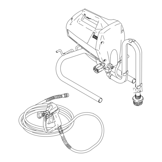
0.24 gpm (0.91 lpm) stand-mount sprayer, 25 ft (7.6 m) hose, and
SG1 spray gun with reversible spray tip and tip guard
2800 psi (19 MPa, 193 bar) Maximum Working Pressure
M
XR7, Model 232745, Series A
AGNUM
0.31 gpm (1.17 lpm) sprayer on heavy-duty cart, 50 ft (15.2 m) hose, and
SG2 metal spray gun with reversible spray tip and tip guard
3000 psi (21 MPa, 207 bar) Maximum Working Pressure
M
XR9, Model 232750, Series A
AGNUM
0.38 gpm (1.44 lpm) sprayer on heavy-duty deluxe cart, 50 ft (15.2 m) hose, and
SG3 pro metal spray gun with reversible spray tip and tip guard
3000 psi (21 MPa, 207 bar) Maximum Working Pressure
M
XR5
AGNUM
Model 232740
This manual contains important
warnings and information.
READ AND KEEP FOR REFERENCE.
t
XR Series Airless Sprayers
9557A
GRACO INC. P.O. BOX 1441 MINNEAPOLIS, MN 55440–1441
9558A
M
XR7
AGNUM
Model 232745
ECOPYRIGHT 2000, GRACO INC.
Graco Inc. is registered to I.S. EN ISO 9001
Form No. 309044
This manual contains service
instructions only. See manual
309043 for operating instructions.
9559A
M
XR9
AGNUM
Model 232750
Rev. B
Advertisement
Table of Contents
Troubleshooting

Related Manuals for Magnum Magnum XR Series


Summary of Contents for Magnum Magnum XR Series
- Page 1 3000 psi (21 MPa, 207 bar) Maximum Working Pressure 9557A 9559A 9558A AGNUM AGNUM AGNUM Model 232740 Model 232745 Model 232750 GRACO INC. P.O. BOX 1441 MINNEAPOLIS, MN 55440–1441 ECOPYRIGHT 2000, GRACO INC. Graco Inc. is registered to I.S. EN ISO 9001...
-
Page 2: Table Of Contents
Table of Contents Warnings ............Component Identification and Function . -
Page 3: Warnings
D Do not smoke in spray area. maximum working pressure. To avoid component rupture and injury, do not operate sprayer D Use only M or Graco airless paint hoses. AGNUM with components rated less than pressure of sprayer. D Use outdoors or in a well-ventilated area. -
Page 4: Component Identification And Function
Component Identification and Function AGNUM 9558A AGNUM 9560A AGNUM 9559A 309044... - Page 5 Component Identification and Function Electric motor (inside of enclosures) Provides mechanical power to pump Power switch For manually turning on/off electrical power to motor (“I” is ON / “0” is OFF) Pressure Control knob For manually increasing (turn clockwise) and decreasing (turn counter-clockwise) fluid pressure in pump, hose, and spray gun Pump fluid outlet fitting Threaded connection for paint hose...
-
Page 6: Pressure Relief Procedure
Pressure Relief Grounding and Procedure Electrical Requirements WARNING WARNING To help prevent injection injuries, follow this procedure when you stop spraying This sprayer requires a 120V AC, 60 Hz, 15A circuit with a grounding receptacle. Never use and before you service or clean the an outlet that is not grounded. -
Page 7: General Repair Information
Freezing fluids can seriously damage the sprayer. Remove any overspray and residue from the air Store the sprayer with mineral spirits/paint thinner or passages and openings in the enclosures whenever Graco Pump Armor to protect equipment during you service the sprayer. storage. 309044... -
Page 8: Basic Troubleshooting
Basic Troubleshooting The following troubleshooting guidelines from the Operating Instructions manual are included here as preemptive measures against Advanced Troubleshooting on page 10. PROBLEM CAUSE SOLUTION Power switch is on and Pressure is set at zero Turn Pressure Control knob (C) clockwise to increase sprayer is plugged in, but pressure. - Page 9 Basic Troubleshooting PROBLEM CAUSE SOLUTION Pressure is set at maximum, Spray tip is too big for Select a smaller spray tip. but cannot achieve a good sprayer. spray pattern. Spray tip is worn beyond Replace spray tip. capability of sprayer. Extension cord is too long or Replace extension cord.
-
Page 10: Advanced Troubleshooting
Advanced Troubleshooting See Pressure Relief See Electric Shock Hazard on Procedure on page 6. page 7. NOTE: See Basic Troubleshooting on page 8 for the problems that are more easily remedied. General Problem: Motor Does Not Operate SPECIFIC PROBLEM CAUSE SOLUTION Power switch is on and See Basic Troubleshooting page 8. - Page 11 Advanced Troubleshooting General Problem: Motor Does Not Operate (continued) SPECIFIC PROBLEM CAUSE SOLUTION Basic Electrical Problems Motor armature is shorting. Check for shorts using armature tester (growler), or perform (Continued) spin test (see Motor Diagnostics on page 16). Replace motor if shorts are evident. See Motor Kit on page 18.
- Page 12 Advanced Troubleshooting General Problem: Circuit Breaker is Tripping SPECIFIC PROBLEM CAUSE SOLUTION Building circuit breaker opens Sprayer electrical wiring is pinched, or insulation Repair or replace any damaged wiring or as soon as sprayer is turned on. is damaged. terminals. Securely reconnect all wires. Wires between pressure control switch and control board are pinched.
- Page 13 Advanced Troubleshooting General Problem: Output is Low or Fluctuating SPECIFIC PROBLEM CAUSE SOLUTION Pump cycles, but output is low See Basic Troubleshooting page 8. or surging. Pump valves are worn. Check for worn pump valves as follows: Prime sprayer with paint. Trigger spray gun momentarily.
- Page 14 Advanced Troubleshooting General Problem: Output is Low or Fluctuating (continued) SPECIFIC PROBLEM CAUSE SOLUTION Motor runs and pump Intake valve ball or outlet valve ball is not Remove and clean valves, and check balls and cycles, but pressure does seating properly. seats for nicks;...
-
Page 15: List Of Kits
Advanced Troubleshooting General Problem: Excessive Pressure is Building Up SPECIFIC PROBLEM CAUSE SOLUTION Spray–Prime/Drain valve Pressure control switch is worn. Replace pressure control switch. actuates automatically, See Pressure Control Switch Kit on page 22. relieving pressure relieving pressure Water or paint entered pressure control switch Clean out and/or dry out, and retry. -
Page 16: Motor Diagnostics
Motor Diagnostics See Service Drawing on page 18. Check for electrical continuity in the motor armature, windings, and brush as follows: Armature Short Circuit Test (Spin Test) See Electric Shock Hazard on page 7. Quickly turn motor fan by hand. If there are no electri- cal shorts, fan coasts two or three revolutions before stopping. -
Page 17: Control Board Kit
Control Board Kit XR5/XR7 Control Board Replacement Kit 243228 XR9 Control Board Replacement Kit 243229 If Control Board Diagnostics (page 16) indicate a damaged control board, replace the control board as follows: XR9 control board shown See Electric Shock Hazard on page 7. -
Page 18: Motor Kit
Motor Kit XR Motor/Drive Housing Replacement Kit 243236 Drive Train Detail shaft bushing Control Board Detail fan shield brace motor mounting screw drive housing Rod/Yoke Detail control motor board o-rings harness right enclosure drive housing gear gear shaft pump yoke pump mounting pin cover plastic washer... - Page 19 Motor Kit XR Motor/Drive Housing Replacement Kit 243236 If Motor Diagnostics (page 16) reveal a damaged motor, or if either of the motor brushes are shorter than 1/4 in. (6.4 mm), or if the motor shaft cannot turn, replace the motor as follows: Disassembly Installation D Read all Installation Notes in service drawing on...
-
Page 20: Pump Service
Pump Service Rod/Yoke Detail XR Pump Repair Kit 243090 (Packing Module) o-rings drive housing eccentric bearing yoke gear shaft packing nut E-clip pump packing spring guide rods o-ring pump cover mounting screw pins pressure plastic washers control harness front cover Drive Train Detail pump 9701A... - Page 21 Pump Service XR Pump Repair Kit 243090 (Packing Module) CAUTION When repairing or cleaning the pump, never submerge the pump in water or allow fluid to enter the pressure control. When the pump packings wear, paint begins to leak down the outside of the pump. Replace the pump packings at the first sign of leaking, or additional damage could occur.
-
Page 22: Pressure Control Switch Kit
Pressure Control Switch Kit XR5 Pressure Control Switch Replacement Kit 243227, 2800 psi (19 MPa, 193 bar) XR7/XR9 Pressure Control Switch Replacement Kit 243521, 3000 psi (21 MPa, 207 bar) If the sprayer stall pressure is too low (motor stops before correct pressure is reached), or excessive variation develops, the pressure control switch may need to be replaced. -
Page 23: Inlet Valve Kit
Pump Service XR Inlet Valve Replacement Kit 243093 / XR Outlet Valve Replacement Kit 243094 yoke guide rods o-ring pump cover front cover screw o-ring suction tube fitting pump 9702A Installation Notes Torque to 400 to 450 in-lb (45 to 51 NSm). Torque to 320 to 380 in-lb (36 to 43 NSm). - Page 24 Pump Service XR Inlet Valve Replacement Kit 243093 / XR Outlet Valve Replacement Kit 243094 CAUTION When repairing or cleaning the pump, never submerge the pump in water or allow fluid to enter the pressure control. If the sprayer continues to cycle (motor and pump run) when the spray gun trigger is released, or if performance is poor even with new spray tips and clean filters, the pump inlet or outlet valve may be obstructed or worn.
-
Page 25: Pump Replacement Kit
Pump Replacement Kit Rod/Yoke Detail XR Pump Replacement Kit 243533 o-rings eccentric bearing gear gear shaft yoke drive housing pump guide rods pump mounting pins cover pressure screw plastic washers control harness pressure control switch (not included with new pump in Kit 243533) front cover Drive Train Detail drain tube... - Page 26 Pump Replacement Kit XR Pump Replacement Kit 243533 CAUTION When repairing or cleaning the pump, never submerge the pump in water or allow fluid to enter the pressure control. Replace the pump as follows: Disassembly Installation D Read all Installation Notes in service drawing on 1.
-
Page 27: Gear/Yoke Kit
Gear/Yoke Kit XR Gear/Yoke Replacement Kit 243230 Replace the gear/yoke assembly as follows: Disassembly Installation D Read all Installation Notes in service drawing on facing page. Pressure Relief on page 6. Procedure D For easier parts placement, tip sprayer backwards during installation. -
Page 28: Spray-Prime/Drain Valve Kit
Spray–Prime/Drain Valve Kit Spray–Prime/Drain Valve Replacement Kit 235014 gasket seat stem (arrow points to pin bore on stem) pump base valve (shipped assembled) Apply thread sealant (included with Kit 235014). handle Apply grease to face of base. 9704A Torque valve into pump manifold to 185 in-lb (21 N.m). Handle is shown in SPRAY position. -
Page 29: Technical Data
Technical Data AGNUM AGNUM AGNUM Working pressure range 0 to 2800 psi 0 to 3000 psi 0 to 3000 psi (0 to 19 MPa, 0 to 193 bar) (0 to 21 MPa, 0 to 207 bar) (0 to 21 MPa, 0 to 207 bar) Electric motor (open-frame, 5.8 Amp 5.8 Amp... -
Page 30: Parts
Parts Model 232740 XR5 Sprayer 309044... - Page 31 Parts Model 232740 XR5 Sprayer Ref. Ref. Part No. Description Qty. Part No. Description Qty. 195110 CORD, power 195126 PUMP, housing 115478 SCREW, torx/slt pan hd, 1/4” 243090 PUMP, repair kit 115499 SWITCH, rocker 243094 VALVE, outlet kit (includes #17) 195431 LEG, left 103338...
-
Page 32: Model 232745 Xr7 Magnum Sprayer
Parts Model 232745 XR7 Sprayer 309044... - Page 33 Parts Model 232745 XR7 Sprayer Ref. Ref. Part No. Description Qty. Part No. Description Qty. 195434 SUPPORT, left 195126 PUMP, housing 195436 FRAME, cart 243090 PUMP repair kit 195435 HANDLE, cart 243094 VALVE, outlet kit (includes #17) 195440 HOSE RACK 103338 PACKING, o–ring 115097...
-
Page 34: Model 232750 Xr9 Magnum Sprayer
Parts Model 232750 XR9 Sprayer 309044... - Page 35 Parts Model 232750 XR9 Sprayer Ref. Ref. Part No. Description Qty. Part No. Description Qty. 195433 SUPPORT, right 195126 PUMP, housing 195434 SUPPORT, left 243090 PUMP repair kit 195439 FRAME, cart 243094 VALVE, outlet kit (includes #17) 195438 HANDLE, cart 103338 PACKING, o–ring, outlet valve 195440...
-
Page 36: Limited Warranty
Graco’s printed recommendations and instructions. This warranty applies for one year from the date of purchase. This warranty does not cover and Graco shall not be liable for general wear and tear, or any malfunction, damage or wear caused by improper use, accidents, user negligence, use of non-Graco component parts or service or repair performed by anyone other than a Graco authorized service center.
Need help?
Do you have a question about the Magnum XR Series and is the answer not in the manual?
Questions and answers