Table of Contents
Advertisement
Quick Links
Download this manual
See also:
Operation
Repair
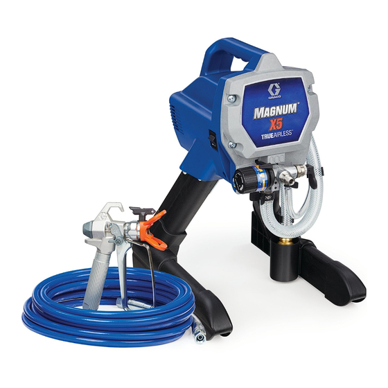
Magnum X5 and X7 Airless Sprayers
- For Portable Spray Applications Architectural Paints and Coatings -
Models:
Magnum X5 (16J750) - Series A
Maximum Working Pressure: 207 bar, 21 MPa (3000 PSI)
Includes:
•
0.91 lpm (0.24 gpm) stand-mount sprayer
•
SG2 gun - Manual 312830
•
0.635 cm (1/4 in) x 7.5 m (25 ft) hose
Magnum X7 (16J751) - Series A
Maximum Working Pressure: 207 bar, 21 MPa (3000 PSI)
Includes:
•
1.17 lpm (0.31 gpm) cart-mount sprayer
•
SG3 gun - Manual 312830
•
0.635 cm (1/4 in.) x 15 m (50 ft) hose
Important Safety Instructions
Read all warnings and instructions in this
manual. Save these instructions.
Magnum X5
(16J750)
- Not for use in explosive atmospheres -
Use water based or mineral-spirit type material only.
Do not use materials having flash points lower than
70°F (21°C). For more information about your mate-
rial request MSDS from distributor or retailer.
Magnum X7
(16J751)
3A1943B
EN
ti17678a
Advertisement
Table of Contents


Need help?
Do you have a question about the X5 and is the answer not in the manual?
Questions and answers