IDS X64 Installer Manual
Remote receiver to connect to an alarm panel
Hide thumbs
Also See for IDS X64:
- Installer manual (96 pages) ,
- User manual (44 pages) ,
- Quick programming manual (37 pages)
Table of Contents
Advertisement
Advertisement
Table of Contents

Related Manuals for IDS IDS X64


Summary of Contents for IDS IDS X64
- Page 2 IDS X64 Remote Receiver 700-408-02A Issued August 2010...
-
Page 3: Table Of Contents
Identify Remote Receiver ....................... 17 2.13 Remote Receiver Test ......................18 2.14 Remote Receiver Capacity ....................19 Troubleshooting ......................20 Factory Settings ........................20 Warnings ..........................21 Registration ..........................21 Startup ........................... 21 IDS X64 Remote Receiver 700-408-02A Issued August 2010... -
Page 4: Overview
Overview Introduction The IDS X64 Remote Receiver is a 433.92 MHz RF receiver that is designed to connect to an IDS X64 Alarm Panel. The receiver connects to the keypad Bus (via D+ and D- terminals), permitting the Alarm Panel to be armed and disarmed from Remote Transmitters. When remotes are learnt, they are assigned to USER CODES stored in the IDS Alarm Panel. -
Page 5: Wiring And Configuration
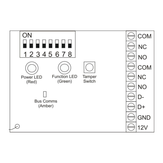
X64 Alarm Panel, or the nearest keypad or zone expander. To avoid mistakes, use sheathed cable with 4 colour-coded cores, and connect identically at each end: 12V RED GND BLACK IDS X64 Remote Receiver 700-408-02A Issued August 2010... -
Page 6: Electrical Specifications
Receiver Frequency: 433.92 MHz Panel Mode These settings only apply to receivers being used with the IDS X64 Alarm Panel. All remotes follow these settings; they cannot be different from one remote to the next. Button Assignment The functions that can be assigned to a button are: arm/disarm, stay, relay 1, and relay 2. Each button can be assigned multiple functions, or no function. -
Page 7: Management Button
Throughout the manual the use of the following terms is used to describe information that appears on the LCD keypad during programming: – Remote Receiver Number – Button Number – Relay Number – Relay State IDS X64 Remote Receiver 700-408-02A Issued August 2010... -
Page 8: Number Assignment
R R R R R R R R R R R R R R R until the DIPswitch is changed to a valid number. The Remote Receiver then restarts normally. IDS X64 Remote Receiver 700-408-02A Issued August 2010... -
Page 9: Add Remote To Panel
Section: 2 Add Remote to Panel Use the following steps to add Remote Transmitters to the Remote Receiver connected to an IDS Alarm Panel via the keypad Bus. [*] [Master Code] [*] [2] [0] [*] [Receiver Number] [*] [User Code] [*] [*] [Press RT Button] [#] LCD Keypad Defaulting of the Remote Receiver is only for new installations of the Remote Receiver. -
Page 10: Add Remote To Panel - Advanced
Manual. Add Remote to Panel – Advanced Use the following steps to add Remote Transmitters to the Remote Receiver connected to an IDS Alarm Panel via the keypad Bus using the management button. [*] [Master Code] [*] [2] [1] [*] [Receiver Number] [*] [User Code] [*] [Management Button] [*]... - Page 11 (i.e. button 1 is arm/disarm, button 3 is stay arm etc.) then all user codes on that Remote Transmitter have to be IDS X64 Remote Receiver 700-408-02A Issued August 2010...
-
Page 12: Delete Remote From Panel
Delete Remote from Panel Use the following steps to add Remote Transmitters to the Remote Receiver connected to an IDS Alarm Panel via the Keypad Bus. [*] [Master Code] [*] [2] [2] [*] [Receiver Number] [*] [User Code] [*] [#] LCD Keypad Hold the [*] key until the beep (3-4 seconds). -
Page 13: Set Remote Receiver Button Properties
The READY LED is on if you are viewing button 1, the ARM LED is on if you are viewing button 2, the AWAY LED is on if you are viewing button 3, and the POWER LED is on if you are viewing button 4. IDS X64 Remote Receiver 700-408-02A Issued August 2010... -
Page 14: Set Remote Receiver Relay Properties
The keypad displays “Remote Receivr N”, “R Secure RS”. At the keypad you can scroll through the properties with the “>>” and “<<” keys. Use [*] to toggle properties. Once you have finished, press the [#] key to exit programming. IDS X64 Remote Receiver 700-408-02A Issued August 2010... -
Page 15: Set Remote Receiver Relay Pulse Time
The keypad displays “Option Menu”, “Add User Code”. Enter [2] [5] followed by the [*] key. The keypad displays “Receiver Num + *”. Enter [RECEIVER NUMBER], which could be 1, 2, 3, or 4, followed by the [*] key. IDS X64 Remote Receiver 700-408-02A Issued August 2010... -
Page 16: Defaulting The Remote Receiver
Hold the [*] key until the beep (3-4 seconds). The keypad displays “Master Code + *”. Enter [MASTER CODE] followed by the [*] key. The keypad displays “Option Menu”, “Add User Code”. IDS X64 Remote Receiver 700-408-02A Issued August 2010... -
Page 17: Identify Remote Receiver
Hold the [*] key until the beep (3-4 seconds). The keypad displays “Master Code + *”. Enter [MASTER CODE] followed by the [*] key. The keypad displays “Option Menu”, “Add User Code”. IDS X64 Remote Receiver 700-408-02A Issued August 2010... -
Page 18: Remote Receiver Test
This command puts the Remote Receiver into test mode for a few minutes. While in test mode, the X64 Alarm Panel ignores buttons pressed on known Remote Transmitters, and the keypad displays their user codes. [*] [Master Code] [*] [2] [8] [*] [Receiver Number] [*] [#] IDS X64 Remote Receiver 700-408-02A Issued August 2010... -
Page 19: Remote Receiver Capacity
The keypad will beep 3 times and then repeat the beeps if the receiver is not registered. To identify more receivers repeat steps 7 and 8. Once you have finished, press the [#] key to exit programming. IDS X64 Remote Receiver 700-408-02A Issued August 2010... -
Page 20: Troubleshooting
LED quick-flashing in groups of three R R R R R R R R R R R R R R R until the DIPswitch is changed to a valid number. The Remote Receiver then restarts normally. IDS X64 Remote Receiver 700-408-02A Issued August 2010... -
Page 21: Warnings
The decimal is indicated by both LEDs flashing quickly. For example, version 2.03 would be displayed as: GGGGGGGGGGGGG G G G G GGGGGGG GGGGGGGGGGGGGGGGGGG R R R R decimal The DIPswitch is debounced while the version is flashing, and is read when flashing is complete. IDS X64 Remote Receiver 700-408-02A Issued August 2010... - Page 22 IDS X64 Remote Receiver 700-408-02A Issued August 2010...
- Page 23 IDS X64 Remote Receiver 700-408-02A Issued August 2010...
- Page 24 IDS X64 Remote Receiver 700-408-02A Issued August 2010...
Need help?
Do you have a question about the IDS X64 and is the answer not in the manual?
Questions and answers