Table of Contents
Advertisement
Quick Links
Advertisement
Table of Contents

Subscribe to Our Youtube Channel
Related Manuals for IDS 400


Summary of Contents for IDS 400
-
Page 2: Table Of Contents
....29 ....29 29 ................30 NTERING AND AVIGATING ROGRAM 4.1.1 Direct Location of Program Mode Setting ..............30 4.1.2 Program Mode Menu Map ..................... 31 M000......................33 IRMWARE ERSION IDS Base Station Receiver 400 700-179-02B Issued January 2009... - Page 3 APPENDIX A ..................................................55 55 ........................55 ECHNICAL OTES 5.1.1 Sescoa Superfast......................55 5.1.2 DSC 4020 Alarm Panel....................56 5.1.3 Guard Master ......................... 56 IDS Base Station Receiver 400 700-179-02B Issued January 2009...
- Page 4 IDS BSR400 RS232 PC (S PC’ 25 W ..........73 TO THE ONNECTOR IDS BSR400 RS232 PC (S PC’ ..........73 TO THE ONNECTOR ................. 74 ONNECTIONS PC C ......................74 IN TO ONNECTIONS IDS Base Station Receiver 400 700-179-02B Issued January 2009...
- Page 5 Table 16 : 4x3 Serial Event Code Identifier…………………………………………….…………….………...48 Table 17 : Event Codes Identifiers………………………………………………………….…………………..48 Table 18 : Serial Out Options……………………………………………………………….…………………..49 Table 19 : Status Report Codes……………………………………………………………………………..…51 Table 20 : Line Card Option Bits……………………………………………………………………………….55 IDS Base Station Receiver 400 700-179-02B Issued January 2009...
-
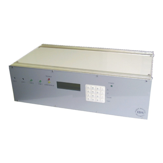
Page 6: Figure 1: Ids Base Station Receiver
Receiver Receiver The INHEP Digital Security (IDS) Base Station Receiver 400 (BSR400) is a standalone specialised multi- format modem receiver for alarm panels. It monitors, decodes and displays alarm events on a user friendly 20 x 4 Liquid Crystal Display (LCD) monitor and provides hard copies of the reports via a standard parallel printer port (Pout). -
Page 7: Specifications
• 2 pin Phoenix Remote Alarm Relay Output, switched 12V - 500mA output. • 3 pin Phoenix Remote Up Arrow and Cancel Key Input, IDS BSR400 only • System Self-Monitoring Facilities. Low battery supply detector, 11.0 to 11.5 volts for faulty battery and/or when the AC input •... - Page 8 Log Event Viewer. View current and previous entries in the event log • TROUBLE event log viewer • Program Mode for setting up IDS BSR400 and Line Card options. M000 – FIRMWARE VER. Control Card version display • M100 – STATION SETUP.
-
Page 9: Full Installation Requirements
2. 2. 2. 2. I I I I nstallation nstallation nstallation nstallation There are three installation variations of the IDS Base Station Receiver apart from the optional number of Line Cards used. Standalone: IDS BSR400 only Intermediate: IDS BSR400 plus a printer... -
Page 10: Connecting Up Full Installation
Parallel Printer Standard Printer Cable P1 IDS Base Station Receiver to PC Adapter Cable (25 Way D type male to 25 Way D type and 9 Way D type sockets) D1 Base-to-Base Adapter Cable (25 Way D type male to 25 Way D type sockets) D2 optional... -
Page 11: Ids Bsr Installation
IDS BSR400: IDS BSR400 IDS BSR400 IDS BSR400 Remove the top cover. Place the battery into the battery holder assembly. Locate and connect the red and black battery cables to the battery. IDS Base Station Receiver 400 700-179-02B Issued January 2009... - Page 12 Place the battery in the battery housing assembly. DO NOT replace the top battery-retaining bracket. Locate and connect the red and black battery cables to the battery. Slide the assembly into the housing and reassemble. IDS Base Station Receiver 400 700-179-02B Issued January 2009...
-
Page 13: Ground Connection
Ground Connection Ground Connection To reduce the risk of light or power surges damaging the IDS BSR400 or PC it is important to connect them as follows: Both units must be plugged into the same main dual wall outlet socket or via a multi socket adapter. -
Page 14: Operation
Once the BCP has established the number of line cards installed in the IDS BSR400, the current settings relevant to each active line card will be transferred to each card. This occurs each time the IDS BSR400 unit is switched off and then on. The BCP will now be in the UN-VIEWED EVENTS state as a result of the most recent events having been loaded into the “Event Log”. -
Page 15: Front Panel Led
On the IDS BSR400 or if the line card software has been upgraded to version 2.00 or higher the line card will not issue a kiss off until the control card has read the received event. If the control card fails to read the event the line card will pulse the LED at a twice the normal rate to indicate a fault condition. -
Page 16: Navigating And Editing
To enter the “Y” “Y” character and then return to the numeric mode: “Y” “Y” Press the SHIFT key then • Press 9 , 9 , 9 (9 key three times) and • IDS Base Station Receiver 400 700-179-02B Issued January 2009... -
Page 17: Viewing Events In The Log
Enter the number of the event locality you want to go to, e.g. 699, 000, 123, and press to move to the 123 event. 03 DEC 2000 16:48 System MSG System Reset IDS Base Station Receiver 400 700-179-02B Issued January 2009... -
Page 18: Version Display, Print And Serial Output Facility
Press the * key to select the output to the printer. 03 DEC 2000 16:48 Unit in Standby Stxt Press the * key to select print format output on the serial port. IDS Base Station Receiver 400 700-179-02B Issued January 2009... - Page 19 If a Ver 2.00 or > is installed and has failed, the same display above will be displayed. Where there is no line card installed the following is displayed: 03 DEC 2000 16:48 Unit in Standby LCx ** Not Active ** IDS Base Station Receiver 400 700-179-02B Issued January 2009...
- Page 20 699 number of events to be outputted from the event log. Key in the number of events required and press the * key to output. The IDS BSR400 will print: DD/MM/YYYY hh:mm:ss LCxx FORMAT ACCT PLAIN LIBRARY XYZ to the printer or output on...
-
Page 21: Ids Bsr400 Setup
3.3.2 3.3.2 3.3.2 Printer Printer Printer Printer If a printer is to be used on the IDS BSR400 use Enable Printer M201 to enable the printer output. 3.3.3 3.3.3 Monitoring Program Set itoring Program Setup 3.3.3 3.3.3 itoring Program Set... -
Page 22: Format Option Selection
= Medical [1...F] = user or [1...F] = zone • Testing Testing Testing Testing Program an alarm panel then test its operation with the IDS BSR400 using the instructions in paragraph 5.1.7 BSR400 – Alarm Panel Communication Test. IDS Base Station Receiver 400 700-179-02B Issued January 2009... -
Page 23: Alarm And System Events
Event and Error Formats Event and Error Formats The following formats are handled by the IDS BSR400. These are received events, 1 to 7 in Table 1: FORMAT Description, error and trouble formats, 8 to 10 in Table 1: FORMAT Description,... - Page 24 The “Un-viewed” event number is the number of events that have been • added to the log while viewing the currently displayed event or the number of events scrolled backwards (down) relative to the latest event entered into the log. IDS Base Station Receiver 400 700-179-02B Issued January 2009...
-
Page 25: Table 1: Format Description
See 4.3.7 Format Options M107 to enable/disable this event being printed 03 DEC 2000 16:48 MISSED CALL NOTE: Subscribe to the Telkom “Call ID” see 3.3.8 General Installations Management System MSG (Trouble) IDS Base Station Receiver 400 700-179-02B Issued January 2009... -
Page 26: Viewing The Trouble Log
TROUBLE Log TROUBLE Log The IDS BSR400 has a separate viewer to display “TROUBLE Event” conditions entered into the Event Log, see Table 2: TROUBLE Conditions. The restore state is not shown but is added to the Event Log as it is displayed on the front panel. -
Page 27: Correcting Trouble Conditions
Correcting TROUBLE Conditions Correcting TROUBLE Conditions For correct operation of the IDS BSR400, there should not be any TROUBLE events and when they occur, the cause and subsequent correction should be determined and attended to as soon as possible. 3.7.1 3.7.1... -
Page 28: Printer Error
Type in an acknowledgement by holding down the Cntl key and pressing the “F” key, if the input to the IDS BSR400 (output from the PC) is “OK” and there are serial events in the event log, the IDS BSR400 will output these serial events to the terminal emulator - acknowledge each output sequence. -
Page 29: Program Mode
M M M Mode rogram The program mode is the means for the user to setup the IDS Base Station Receiver to suit the user’s system configuration. NOTE: The formats of the Program Mode displays are different between Base Control card version V1.01 and lower and V1.02 upwards. -
Page 30: Program Mode Program Mode
Primary and Secondary boxes above it, or note the number in the Setting heading. Press the # key. M_-- is displayed at the bottom right hand corner of the LCD overwriting the current location IDS Base Station Receiver 400 700-179-02B Issued January 2009... -
Page 31: Program Mode Menu Map
4. Press [ * ] to select or [ Cancel] to abort. - If digits are out of range the input is cleared and the process returns to step 2. SOUT Options Figure 6: Program Mode Menu Map IDS Base Station Receiver 400 700-179-02B Issued January 2009... -
Page 32: Table 3 : Program Mode Menu
Delay Between Sout M421 Heart Beat Period M422 Ack Wait Period M423 Event/Ack Repeats M424 LINE CARD SETUP M500 LC 1 Each with M510 LC 2 sub-menus M520 LC 3 shown M530 IDS Base Station Receiver 400 700-179-02B Issued January 2009... -
Page 33: Firmware Version M000
The event log is not reset, if this is required contact the supplier. To reset to the system defaults: Locate the “Load Default” setting and press * to select the setting • IDS Base Station Receiver 400 700-179-02B Issued January 2009... -
Page 34: Clear Un-Viewed Count M106
M106 M106 This is a facility to clear the un-viewed event count where an IDS BSR400 is connected to a “Monitoring” program and the user requires to view the latest events on the IDS BSR400 Display panel without having to scroll through all un-viewed events first. - Page 35 If there is no response to any of the handshakes due to an erroneous call or if the alarm panel is unable to detect its desired handshake, the line card reports a “Missed Call”. This record was not IDS Base Station Receiver 400 700-179-02B Issued January 2009...
-
Page 36: Table 4: Format Out Options
Disable/Enable Rx'ed Missed Calls printing. 0 – Disable serial and print output. 1 – Enable serial and print output (Default). Disable/Enable Comms Absent/Restoral output. 0 – Disable serial and print output. IDS Base Station Receiver 400 700-179-02B Issued January 2009... -
Page 37: Rinter Etup M200
01..04 above. This function may be used at any time, during the assigned period, to reprint logged events and output them on Sin port. Example: Select [1, 2, 3 or 4] above then: IDS Base Station Receiver 400 700-179-02B Issued January 2009... - Page 38 08:30 CONT ID 1234 Panic Event E120 00001 010 The selected number of event will be output on the Sin serial port or Printer port depending on the selection made above. IDS Base Station Receiver 400 700-179-02B Issued January 2009...
-
Page 39: Plain Library M202
* . Press CANCEL to abort any changes. IDS Base Station Receiver 400 700-179-02B Issued January 2009... -
Page 40: Vent Larm Etup M300
M300 M300 The IDS BSR400 may be programmed to sound the buzzer or operate the relay when an alarm panel event is entered into the “Event Log”. These settings enable the user to configure the buzzer and relay operation together or separately and select the switch off method. The common TAGGED event settings enable the buzzer/relay on specific events. -
Page 41: Event Relay M302
Codes enter a 0 or 1 to correspond with the code group in Table 8: Contact ID [10x...42x] Event Type Buzzer Enable and Table 9: Contact ID [44x...63x] Event Type Buzzer Enable that corresponds to the header field above the entry field, the default selection is shown below. IDS Base Station Receiver 400 700-179-02B Issued January 2009... -
Page 42: Table 8: Contact Id [10X
30x – 31x System Trouble Sounder/Relay Trouble 33x – 34x System Peripheral Trouble 35x – 36x Communication Trouble Protection Loop Trouble Sensor Trouble Open/Close Remote Access Access Control 44x – 45x Special O/C IDS Base Station Receiver 400 700-179-02B Issued January 2009... -
Page 43: Sia Tagged Buzzer Events M306 M307
5 until the “Header” number to be changed is reached and enter the new tag value. Press to select other header fields. Press until the last field then press to save and end entry process. IDS Base Station Receiver 400 700-179-02B Issued January 2009... -
Page 44: Wake-Up Alarm M308
The IDS BSR400 provides serial output (Sout) communication port facility to pass status and event information to a PC based monitoring program. When enabled the IDS BSR400 will output the heart beat (polling) sequence terminated by a [DC4] control character to establish and maintain communications with the monitoring program, see 4.6.4 Heart Beat (Poll) Date/Pre/Post M413. -
Page 45: Format M41X
The IDS BSR400 has a Date Stamp (date, time, and year) option that may be enabled as a pre-fix or post-fix to either the event or heart beat (poll) outputs or both. The serial protocol must be as follows:... -
Page 46: Enable Year Output M414
Table 16 below. During the serial output sequence, the entered event code identification characters are selected from the format tables according to the value of the most significant digit of the received event code and placed in the “X” position in the serial output sequence. IDS Base Station Receiver 400 700-179-02B Issued January 2009... - Page 47 Disarming by user (Open) 1012 1234 A 6F[DC4] See Note 2 PRRLssssAAAAAAsXGYYY[DC4] NOTE 1: See Sescoa Second Digit regarding the use of the second most significant digit of the received Sescoa event code. IDS Base Station Receiver 400 700-179-02B Issued January 2009...
-
Page 48: Table 14: 3X1 And 4X1 Serial Event Code Identifier
“6F” to “A6F” or “06F” where “A” is converted to a “0”. The above to case may be use to change an event code “A6F” to “R6F” required by the monitoring software. IDS Base Station Receiver 400 700-179-02B Issued January 2009... -
Page 49: Sout Option M419
M107 process have been moved to 4.3.7 Format Options SIA Output Format The IDS BSR400 supports “Level 1” and “Level 2” serial output 0 – Protocol 1 SIA serial output. • 1 – Protocol 2 SIA serial output (Default). •... -
Page 50: Heart Beat Period M422
Basic Signal Protocol [1] Basic Signal Protocol [1] The IDS BSR400 uses this protocol type to report 4/1, 4/2, 4/3 “Pulse” and 4x2 DTMF event formats. See 4.3.7 Format Options M107 for additional user selectable modification to the event codes. -
Page 51: Supervisory Poll (Heart Beat) Signal Protocol [1]
Status Report Messages [1] Status Report Messages [1] The IDS Base Station Receiver will send the following messages to Sout Port to report internal status conditions and will use the account code “0000” to indicate that it is reporting an internal condition. -
Page 52: Sia-Id Protocol 1 [3]
The SIA Protocol 1 cannot handle cretin information in SIA level 2 and 3. Where these levels are used the SIA Protocol 2 must be selected, see 4.6.8 Sout Option M419. The IDS BSR400 sets the RR and L to the source of the received event, changes any account code value “A”... -
Page 53: Telephone Number Protocol (Call Id) [4]
ID Protocol [5] ID Protocol [5] The IDS BSR400 sets the RR and L to the source of the received event, changes any account code value “A” to a “0” and outputs the remaining information as received. PRRLs18AAAAQXYZGGCCC[DC4] – Where... -
Page 54: Handshake Duration M5X2
This may be corrected by changing the time the IDS Base Station Receiver waits for the alarm panel to acknowledge the handshake. -
Page 55: Line Card Options M5X7
“A”, e.g. the coded account code 1234 = 574 + the m.s.d. of the event code “A” which will be seen by the IDS BSR400 as part of the account code and will be converted to a “0”, the result is account code 5740. -
Page 56: Dsc 4020 Alarm Panel
When setting up to an existing installation using this monitoring program it may be necessary to alter the Event Code output format to the monitoring program. This may occur when you replace OEM base station with the IDS BSR400. See paragraph 4.3.7 Format Options M107. 5.1.5 5.1.5... - Page 57 If none of the messages sent to the monitoring program received an “Acknowledge” or if the communication link is disconnected then communications failed system messages should occur. 10 APR 2007 16:48 System MSG COMMS ABSENT IDS Base Station Receiver 400 700-179-02B Issued January 2009...
-
Page 58: Reset The Base Station
To RESET the BSR400 remove the top cover, locate the "Control Card", shown below, which • is the card on the left hand side of the Display and has a RED and YELLOW LED. Locate the pins back card bottom assembly. IDS Base Station Receiver 400 700-179-02B Issued January 2009... -
Page 59: Bsr400 - Alarm Panel Communication Test
Above the 400 of the label IDS BSR$400 CONTROL CARD Ver D, identified as CN3. Switch off the BSR400, hold a screwdriver across CN3 and switch on the BSR400. When the Display shows "LOADING DEFAULTS" remove the screwdriver. The BSR400 should now operate as normal. - Page 60 Get a Venus plug to plug adapter cable, cut the cable in half, strip 100 to 150 millimetre of the PVC sleeving off, cut off the black and yellow wires and connect banana plugs to the red and green wires. See below Using the adapter IDS Base Station Receiver 400 700-179-02B Issued January 2009...
-
Page 61: Appendix Bappendix
Outdoor Tamper Near Alarm Silent Burglary General Alarms – 140 General Alarm Polling Loop Open Polling Loop Short Expansion Module Failure Sensor Tamper Expansion Module tamper Silent Alarm Sensor Supervision Failure IDS Base Station Receiver 400 700-179-02B Issued January 2009... - Page 62 Battery Missing/Dead Power Supply Over current Engineer Reset Sounder/Relay Troubles – 320 Sounder/Relay Bell 1 Bell 2 Alarm Relay Trouble Relay Reversing Relay Notification Appliance Ckt. #3 Notification Appliance Ckt. #4 IDS Base Station Receiver 400 700-179-02B Issued January 2009...
- Page 63 Sensor Tamper RF Low Battery Smoke Detector Hi Sensitivity Smoke Detector Low Sensitivity Intrusion Detector Hi Sensitivity Intrusion Detector Low Sensitivity Sensor Self-test Failure Sensor Watch Trouble Drift Compensation Error Maintenance Alert IDS Base Station Receiver 400 700-179-02B Issued January 2009...
- Page 64 Exception O/C Early O/C Late O/C Failed to Open Failed to Close Auto Arm Fail Partial Arm Exit Error (User) User on premises Recent Close Wrong Code Entry Legal Code Entry IDS Base Station Receiver 400 700-179-02B Issued January 2009...
- Page 65 Status Report to Follow Listen-in to Follow Walk Test Mode Periodic Test – System Trouble Present Video Transmitter Active Point Tested OK Point not Tested Intrusion Zone Walk Tested Fire Zone Walk Tested IDS Base Station Receiver 400 700-179-02B Issued January 2009...
-
Page 66: Control Block Data Code Definitions (Sia Table 4)
Control Block Data Code Definitions (SIA Table 4) Control Block Data Code Definitions (SIA Table 4) Kill Listen-in Switch Listen-in Output Pulse Output Relay Set Area Set Bypass Set Sounder Set Warning Trap Cancel Trap Account IDS Base Station Receiver 400 700-179-02B Issued January 2009... -
Page 67: Program Block Data Code Definitions (Sia Table 5)
Burglary Supervisory Burglary Trouble Burglary Un-bypass Burglary Verified Burglary Test Missing Supervision Automatic Closing Closing Delinquent Closing Extend Forced Closing Close Area Fail to close Late Close Early Close Closing Report IDS Base Station Receiver 400 700-179-02B Issued January 2009... - Page 68 Fire Bypass Fire Cancel Fire Alarm Restore Fire Test Begin Fire Trouble Restore Fire Test End Fire Alarm - Cross Point Fire Restoral Fire Supervisory Fire Trouble Fire Un-bypass Fire Test IDS Base Station Receiver 400 700-179-02B Issued January 2009...
- Page 69 Heat Trouble Restore Heat Restoral Heat Supervisory Heat Trouble Heat Un-bypass Local Program Local Program Denied Listen-in Ended Listen-in Begin Phone Line Restoral Local Program Success Phone Line Trouble Local Program Fail IDS Base Station Receiver 400 700-179-02B Issued January 2009...
- Page 70 Emergency Bypass Emergency Alarm Restore Emergency Trouble Emergency Restoral Emergency Supervisory Emergency Trouble Emergency Un-bypass Remote Programmer Call Failed Remote Program Begin Relay Close Remote Program Denied Remote Reset Relay Open IDS Base Station Receiver 400 700-179-02B Issued January 2009...
- Page 71 Printer Paper Out Printer Restore Printer Trouble Printer Test Printer Online Printer Offline Water Alarm Water Bypass Water Alarm Restore Water Trouble Restore Water Restoral Water Supervisory Water Trouble Water Un-bypass IDS Base Station Receiver 400 700-179-02B Issued January 2009...
-
Page 72: Environmental Block Data Code Definitions (Sia Table 7)
Environmental Block Data Code Definitions (SIA Table 7) Environmental Block Data Code Definitions (SIA Table 7) Environmental Block Data Code Definitions (SIA Table 7) Temperature Report Air Flow Report Humidity Report Fluid Level IDS Base Station Receiver 400 700-179-02B Issued January 2009... -
Page 73: Appendix Dappendix D
PC’s 9 out) to the PC’s 9 Way Connector Way Connector The following are the connections for the serial cable between the IDS BSR/400 and a PC with a 9 Way D type connector. Device Connector Description Device Connector Description... -
Page 74: Base (Sout) To Base (Sin) Connections
NOTE: The cable lines crosses over from pin 2/3 on the IDS BSR/400 to pin 3/2 on the PC. As the connectors are both FEMALE, it is best to connect both lines and mark the cable to identify that it is a CROSSOVER cable. - Page 75 IDS Base Station Receiver 400 700-179-02B Issued January 2009...
- Page 76 IDS Base Station Receiver 400 700-179-02B Issued January 2009...
Need help?
Do you have a question about the 400 and is the answer not in the manual?
Questions and answers