Table of Contents
Advertisement
Quick Links
Advertisement
Table of Contents

Related Manuals for Harman Kardon HKTS 60BQ/230


Summary of Contents for Harman Kardon HKTS 60BQ/230
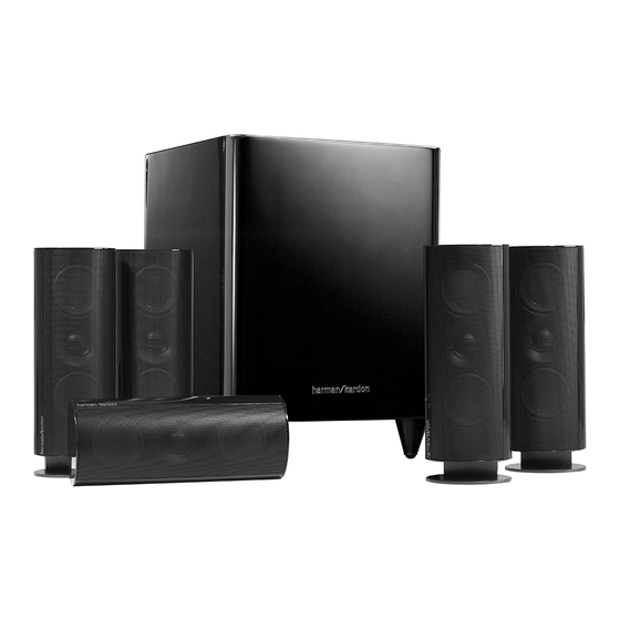
- Page 1 Home Theater Speaker System User Guide English Designed to Entertain. ™...
-
Page 2: Important Safety Instructions
2004/108/EC – EMC Directive, as amended. 1999/5EC – R&TTE Directive, as amended. 2006/95/EC – Low Voltage Directive, as amended 2005/32/EC – Energy Using Products Directive, as amended Harmonized Standards Applied to show Conformity: Harman Kardon® HKTS 60 EN 55013:2001+A1:2003+A2:2006 EN 55020:2007 EN 61000-3-2:2006 EN 61000-3-3:1995+A1:2001+A2:2005... -
Page 3: Description And Features
The speaker cables all use a color-coding system to conform to the Consumer Electronics Association (CEA) standard. This color-coding system minimizes confusion when connecting the speakers, especially when you are connecting them to a Harman Kardon One 4-meter (13.1-foot) speaker cable for receiver. - Page 4 HKTS200SUB Rear-Panel Connections PL0004-01001 Subwoofer Level Control: Use this control to adjust the HKTS200SUB’s volume. Turn Line-Level LFE In Connector: Use the LFE (purple) connector of the supplied clockwise to increase the volume; turn counterclockwise to decrease the volume. combination LFE and trigger cable to connect the Line-Level LFE In to the dedicated subwoofer output of a receiver or preamp/processor.
-
Page 5: Speaker Placement
Speaker Placement Color-Coding System The two surround speakers should be placed slightly behind the listening position, facing each other and, ideally, should be 5–6 feet (1.5m–1.8m) from the floor. An alternate The HKTS 60 use the channel color-coding system established by the CEA to make setting location would be on a wall behind the listening position, facing forward. - Page 6 NOTE: If you’re running the speaker wire through the wall you can bring it out directly Connect the speaker wire to the speaker terminals as shown in the illustration: behind the bracket location and insert it through the bottom opening in the wall portion Press down on the top of the terminal to open the connection hole.
-
Page 7: Speaker Connections
Attach the center speaker wall-mount bracket to the wall using hardware that is the ( + ) terminal and black for the ( – ) terminal. Newer Harman Kardon receivers appropriate for the wall’s construction and materials. Attach the anchors through the conform to the CEA standard and therefore use a color other than red to denote the ( + ) holes shown in the illustration. - Page 8 Left Front Center Right Front Front Left Center Front Right Speaker Cable Speaker Cable Speaker Cable (White Bands) (Green Bands) (Red Bands) – – – FRONT SURROUND CENTER + – + – RIGHT LEFT LFE OUT + – + – PL0004-01001 Subwoofer Receiver...
- Page 9 Left Front Center Right Front Front Left Center Front Right Speaker Cable Speaker Cable Speaker Cable (White Bands) (Green Bands) (Red Bands) – – – FRONT SURROUND CENTER + – + – RIGHT LINE-LEVEL LEFT OUTPUTS + – + – PL0004-01001 Subwoofer Receiver...
- Page 10 Receiver FRONT SURROUND CENTER + – + – RIGHT LFE SUB LEFT TRIGGER OUTPUT OUTPUT + – + – Subwoofer Trigger Cable (Black Ends) PL0004-01001 Connecting to a Trigger Voltage Source If your preamp/processor or another audio/video component has a trigger voltage connection that supplies between 3 and 30V (AC or DC), connect it to the HKTS200SUB’s External Trigger Input Connector .
-
Page 11: Operation
Operation Troubleshooting Turning the Subwoofer On and Off If there is no sound from any of the speakers: Set the HKTS200SUB’s Power Switch to the position. Check that the receiver/amplifier is on and a source is playing. If the Power On Mode Switch is set to , the HKTS200SUB will Make sure that all wires and connections between the receiver/amplifier and the... -
Page 12: Specifications
© 2009 Harman International Industries, Incorporated. All rights reserved. Features, specifications and appearance are subject to change without notice. Harman Kardon is a trademark of Harman International Industries, Incorporated, registered in the United States and/or other countries. Designed to Entertain is a trademark of Harman International Industries, Incorporated.
Need help?
Do you have a question about the HKTS 60BQ/230 and is the answer not in the manual?
Questions and answers