Moog Minimoog Operation Manual
Synthesizer
Hide thumbs
Also See for Minimoog:
- User manual (57 pages) ,
- Technical & service manual (55 pages) ,
- Patch list (28 pages)
Advertisement
Advertisement
Table of Contents

Subscribe to Our Youtube Channel
Related Manuals for Moog Minimoog


Summary of Contents for Moog Minimoog
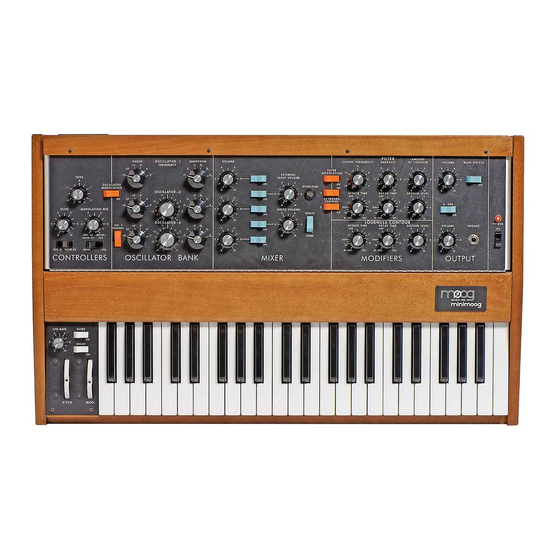
- Page 2 MINIMOOG MODEL D FRONT PANEL...
- Page 3 The purpose of this manual is to acquaint you with the component cir- cuitry of the Mini Moog and the operation of each of the controls and switches regulating the generators, modifiers, and control devices involved in the synthesizing of a musical sound.
-
Page 4: Setting Up The Instrument
These control signals are responsible for all of the musically significant changes and contours in the musical sounds produced by the Mini Moog. TIMING signals come from the keyboard (or from an external source) and are used to trigger, or start off, the contours which open and close the filter and amplifier. -
Page 5: Output Section
LOW level MAIN OUTPUT jack on the rear connector strip of the Mini Moog to an input on your amplifier. If you are using a monitor amplifier, you will need to use the other cord. -
Page 6: Oscillator Bank
Turn on the POWER switch (P). The instrument should generally be given about ten minutes to warm up before tuning and playing. Once warmed up, there is practically no limit to the length of time it may be kept on and in use. Turn on switches (B) and (C) and the MAIN OUTPUT switch (M). - Page 7 The triangular waveform has the least harmonic content; the narrow rectangular has the most. Generally your ear will be your best guide in deciding which waveform to use for a particular quality. The VOLUME control (12) adjusts the amount of Oscillator 1 signal which is fed to the mixer, while switch (C) instantly turns the oscillator on or off.
-
Page 8: Modulation Mix
CONTROLLERS This section will demonstrate the use of the controls located to the left of the Oscillator Bank (used in tuning and setting up a sound), as well as the keyboard and the manual controls on the panel to its left (used during performance). All of these controls have an effect on the oscillators’... - Page 9 Fig. 4 Change the setting of Oscillator 3’s WAVEFORM switch and you will notice the change in the shape of the modulation. You should actually be able to hear the contours of the different waveforms-- the alternation of high and low tones in the square wave, the repeated upward glissandi of the sawtooth, etc.
-
Page 10: Other Controllers
1 1 ) The TUNE control (1) is used to tune up the Mini Moog oscillators to the pitch of the ensemble in which it is being used, or to its A-440 reference tone. - Page 11 Mini Moog. Fig. 5 1 ) The OSCILLATOR VOLUME controls (12, 13, and 14) are used to regulate the relative levels of the audio signals produced by the three oscillators.
- Page 12 The controls on the Modifiers section should still be set as shown in Fig. 1 of Section D. FILTER The Mini Moog features a wide-range lowpass filter. This filter attenuates, or cuts out, those frequency components of an audio signal which lie above a variable cutoff frequency, while passing those components which lie below it.
- Page 13 Set the CUTOFF FREQUENCY to -2 and repeatedly depress and hold down a key while setting the AMOUNT OF CONTOUR at various levels. more this control is turned up, the greater will the increase and decrease in the brightness of each note. Controls (17) and (19) have an additive effect on the cutoff frequency.
- Page 14 attack; the drop will become more gradual as the decay time i n c r e a s e s . 5 ) The SUSTAIN LEVEL control (22) determines the frequency at which the contour levels off after the initial rise and fall. frequency of the sustain level can be as high as the initial peak, in which case there is no decay after the initial rise, or it can be as low as the frequency at which the contour began.
- Page 15 When the EMPHASIS control is set to 10, the Filter breaks into oscillation, and produces a pure sine wave tone. thus is available as a sixth sound source within the MiniMoog. The pitch of this additional oscillator may be controlled by the five other controls on keyboard.
-
Page 16: Loudness Contour
LOUDNESS CONTOUR The volume of the audio signal which passes through the Modifiers section of the Mini Moog is contoured by the Loudness Contour controls. These controls are connected to a contour generator which supplies a control signal to the amplifier. - Page 17 STANDARD ACCESSORIES SHIPPED WITH MINI-D SYNTHESIZER 1 ) Mini brochure & 1971 Catalog 2 ) Mini Instruction Manual 3 ) Warrantee (Reg. Postcard) 4 ) Shorting S-Trig Plug 5 ) "Back Panel Adjustment" Pamphlet 6 ) 6’ Phone Cord 7 ) 6’ Phone - Phono Cord 8 ) Optional Accessories List 7 0 - 0 1 4...
- Page 18 S-TRIG PLUG FOR MINI MOOG MODEL D When inserted, this plug keeps the contour generators "on" continuously. It can be wired to an accessory foot switch for manual external triggering of notes. NORM. OPEN WIRING OF SWITCH TO S-TRIG PLUG...
- Page 19 24 events (example: 24 note repeating bass line). The 961 extends flexibility in triggering the contour generators and can be used to synchronize the MINI MOOG with external equipment (example: tape recorded click t r a c k ) . AVAILABLE SOON FOOT SWITCH A pair of these will allow the performer to engage momentar- ily GLIDE and DECAY functions.*...
-
Page 20: Left Hand Controller
GLIDE and DECAY functions. R. A. Moog will soon make these momentary switches available as an accessory. With no external switch connected and the GLIDE switch turned "off"... - Page 21 T Y P I C A L S-260 JACK R I N G T I P S L E E V E S H I E L D S H I E L D R I N G T I P S L E E V E 2 CONDUCTOR S H I E L D E D C A B L E...
- Page 22 MINI MOOG MODEL D Back Panel Adjustments (on instruments with serial number 1237 and higher) As with any fine musical instrument, the MINIMOOG may require periodic tuning and adjustment. Holes in the back panel provide access to internal trim potentiometers for necessary adjustments.
- Page 23 Using a small screwdriver with an insulated handle, turn OSCILLATOR 1 high end adjustment (A) and tune OSCILLATOR 1 using zero beat method two octaves above the reference os- cillator. (Do not touch metal shaft of screwdriver as this will affect tuning). Depress lowest A on keyboard and zero beat one octave below reference oscillator, using OSCILLATOR 1 low end adjustment (B).
- Page 24 C R E D I T S F O R T H I S M A N U A L Ultimate Credit to: Bob Moog and all the folks at Moog Music Inc The original Manual was written by the excellent:...
Need help?
Do you have a question about the Minimoog and is the answer not in the manual?
Questions and answers