Table of Contents
Advertisement
WARNING – When using electric products, basic precautions should always be followed, including the following:
1) Read all the instructions before using the product.
2) Do not use this product near water – for example, near a bathtub, washbowl, kitchen sink, in a wet basement, or
near a swimming pool or the like.
3) This product should be used only with a cart or stand that is recommended by the manufacturer.
4) This product, in combination with an amplifier and headphones or speakers, may be capable of producing
sound levels that could cause permanent hearing loss. Do not operate for a long period of time at a high volume
level or at a level that is uncomfortable. If you experience any hearing loss or ringing in your ears, you should consult
an audiologist.
5) The product should be located so that its location does not interfere with its proper ventilation.
6) The product should be located away from heat sources such as radiators, heat registers, or other products that
produce heat.
7) The product should be connected to a power supply only of the type described in the operating instructions or as
marked on the product.
8) The power-supply cord of the product should be unplugged from the outlet when left unused for a long period of
time.
9) Care should be taken so that objects do not fall and liquids are not spilled into the enclosure through openings.
10) The product should be serviced by qualified personnel when:
a) The power-supply cord or the plug has been damaged; or
b) Objects have fallen, or liquid has been spilled onto the product; or
c) The product has been exposed to rain; or
d) The product does not appear to operate normally or exhibits a marked change in
performance; or
e) The product has been dropped or the enclosure damaged.
11) Do not attempt to service the product beyond that described in the user-maintenance instructions. All other
servicing should be referred to qualified service personnel.
DANGER: INSTRUCTIONS PERTAINING TO RISK OF FIRE, ELECTRIC SHOCK, OR INJURY TO PERSONS: Do not open the
chassis. There are no user serviceable parts inside. Refer all servicing to qualified personnel only.
GROUNDING INSTRUCTIONS:
This product must be grounded. If it should malfunction or breakdown, grounding provides a path of least resistance
for electrical current to reduce the risk of electric shock. This product is equipped with a cord having an equipment
grounding connector and a grounding plug. The plug must be plugged into an appropriate outlet that is properly
installed and grounded in accordance with all local codes and ordinances.
DANGER – Improper connection of the equipment-grounding connector can result in a risk of electric shock. Check
with a qualified electrician or serviceman if you are in doubt as to whether the product is properly grounded. Do not
modify the plug provided with this product – if it will not fit in the outlet, have a proper outlet installed by a qualified
electrician.
IMPORTANT SAFETY INSTRUCTIONS
SAVE THESE INSTRUCTIONS
Advertisement
Table of Contents

Related Manuals for Moog Minimoog VOYAGER


Summary of Contents for Moog Minimoog VOYAGER
- Page 1 IMPORTANT SAFETY INSTRUCTIONS WARNING – When using electric products, basic precautions should always be followed, including the following: 1) Read all the instructions before using the product. 2) Do not use this product near water – for example, near a bathtub, washbowl, kitchen sink, in a wet basement, or near a swimming pool or the like.
-
Page 2: Table Of Contents
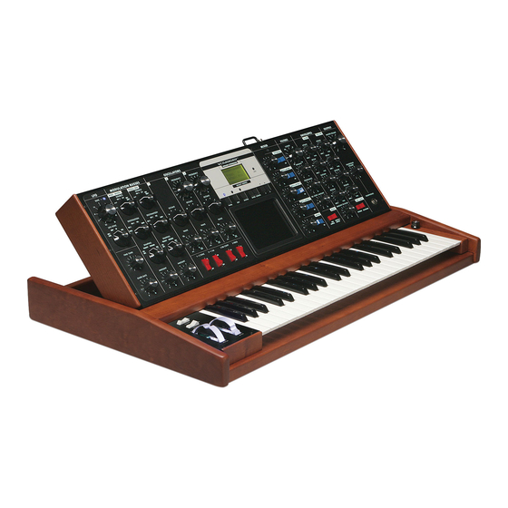
Here it is – the minimoog Voyager. Moog Music has put more than 30 years of experience with analog synthesizer technology into the design of this instrument to bring you the fattest lead synthesizer since the minimoog was introduced in 1970. -
Page 3: Getting Started
Before you get started with your Voyager, please fill out your warranty registration card and send it to Moog Music Inc. This will activate your warranty and is a vital piece of information for us to provide you with the best service. - Page 4 -Power up Turn the power on. You will see the screen light up and display: “minimoog Voyager by moog music”. After about 5 seconds the greeting screen disappears and you will see the MASTER mode options. The LED labeled “MASTER” will be lit. The buttons labeled “PANEL”, “EDIT”, and “MASTER” access the 3 operating modes of the Voyager.
- Page 5 press ENTER. The sound produced by the Voyager is now determined by the settings of the front panel independently of preset memory. When working with the Voyager, keep in mind that many of the controls are interactive, so there is frequently more than one way to control a single parameter. For instance, if the sustain level of the Volume Envelope is all the way down, and the attack and decay times are at zero, there will be no output.
-
Page 6: The Basics Of Analog Synthesis
II. THE BASICS OF ANALOG SYNTHESIS For those getting started in the world of electronic music, let’s take a few moments to go through the basics of sound and synthesis. This will help you understand what the front panel controls do. In order to understand synthesis, one must have a basic working knowledge of the characteristics of sound. - Page 7 Amplitude – The strength of a sound’s vibration measured in Decibels (dB). This corresponds to the musical term Loudness (figure 4). Harmonic Content – A sound is made up of simple vibrations at many different frequencies (called harmonics) which give a sound its particular character. This corresponds to the musical term timbre or tone color.
- Page 8 In general, “synthesis” refers to the generation of sound through a group of amplified circuits over which the programmer/performer has power to change volume, pitch, timbre and articulation. The Minimoog Voyager is based on what is called “subtractive synthesis”. This method of synthesis employs a harmonically rich (think bright-sounding) source material, and then removes frequency components to create the desired sound.
- Page 9 Filter: A circuit that removes some frequencies and allows other frequencies to pass through the circuit. A filter has a cutoff frequency that determines the point at which frequencies begin to be removed. A lowpass filter is one in which frequencies above the cutoff frequency are removed and all frequencies below the cutoff are passed through.
- Page 10 Control Voltage - Control voltages (also called CVs) are used in analog synthesizers to affect changes in the sound. In the case of pitch, pressing a key on the keyboard sends a control voltage that determines the pitch of the oscillators. The pitch can also be changed by a voltage provided from a panel control, such as an oscillator tuning control.
- Page 11 Modulation - Modulation is the use of a CV to affect a voltage-controlled circuit. Modulation has a source, destination, and amount. This could be as simple as the filter cutoff of a VCF (a modulation destination) being changed by the front panel cutoff control (the source), or as complex as mixing multiple CVs together to modulate filter cutoff.
- Page 12 Low Frequency Oscillator - Also called an LFO, this is a special type of voltage controlled oscillator that oscillates primarily below the range of human hearing. LFOs are typically used as a source of modulation. For instance - an LFO with a triangle waveform at about 6 Hz modulating the pitch of a VCO sounds like vibrato.
-
Page 13: The Voyager's Features
III. The Voyager’s Features The minimoog Voyager is a monophonic analog synthesizer that is a descendant of the classic minimoog. Its sound sources are an external audio input, a noise source, and three analog, variable waveform oscillators. The Voyager has front panel... - Page 14 The back panel offers the many connections available, including the power, MIDI, CV, and audio connections (figure 13). For the Control Inputs, a blue nut indicates a gate/footswitch input and a red nut indicates a CV/ expression pedal input. - The Oscillator section includes controls for choosing the octave, the tuning of the second and third oscillators, the oscillators’...
- Page 15 - When a key is pressed, A Gate and Pitch CV are produced by the keyboard. The Gate signal is used to trigger both the Filter and Volume Envelopes. The Pitch CV is used to determine the pitch of the Oscillators and can be applied to a varying degree to the Filters through the Keyboard Control Amount knob.
- Page 16 - The LFO is assigned through the MOD Busses. It features a triangle and square wave. It is also used to trigger the Sample and Hold. - The touch surface controller can control three parameters (X,Y,A) simultaneously. The position of a finger on the touch pad generates a control voltage for horizontal (X) position and a control voltage for vertical (Y) position.
-
Page 17: The Voyager's Components
IV. The Voyager’s Components MIXER The Mixer combines the main sound sources of the Voyager. It’s the place to start when creating a new sound from scratch, or figuring out how a sound is put together. All the sound sources can be turned on or off, and their levels can be adjusted. - Page 18 amount of soft clipping is occurring. When the LED is bright, the signal is really strongly overdriven. Judicious use of overdrive can really fatten up a sound. The external audio input can accept a signal from instrument level to line level. MIX-OUT LOOP: The jack on the back labeled “mix out/filter in”...
-
Page 19: Oscillators
B. OSCILLATORS The Oscillators are the main sound source of the Voyager. The oscillators in the Voyager are all analog Voltage Controlled Oscillators, or VCOs. They feature a temperature regulation circuit that provides them with excellent tuning stability. The VCOs can produce a total musical range of 8 ½ octaves! In addition, the frequency of oscillator 3 can be set to sub-audio (<20Hz) vibrations for use as a second LFO. - Page 20 relative to Osc. 1. This allows more than one frequency to be played when a key is pressed, or to get a very swirly sound when the oscillators are slightly out of tune. Oscillator 1 does not have a frequency control because it is designed to serve as a reference oscillator for the other 2 oscillators.
- Page 21 1 FM: Direct Linear Frequency Modulation of Osc. 1 by Osc. 3 When an Oscillator is used as a CV source for another VCO, it is called Frequency modulation. Frequency Modulation effects can vary from vibrato or trill effects to clangorous inharmonic sounds to rich timbres that evoke acoustic sounds.
-
Page 22: Filters
FILTERS Ahh… the Moog filter – the sound that started it all… Filters are used for transforming the character of an audio signal. Filters are used to modify a sound by stopping some frequencies and allowing others to pass through. An important term regarding filters to understand is “Cutoff Frequency”. - Page 23 When the resonant peaks of the lowpass filters pass through the overtones of the sound being filtered, those overtones are reinforced. This gives the filter a nice character that sounds vocal, quacky, or zappy, depending on how it’s used. When the resonance is turned up past 8, the filters begin to self-oscillate at the cutoff frequency, producing a sine wave tone.
- Page 24 HIGHPASS LOWPASS MODE: In Highpass/Lowpass mode, the Voyagers filters are configured as a lowpass and highpass filter in series, summed to both outputs. As with the dual lowpass mode, the Cutoff control changes the cutoff frequency of both filters, and the spacing sets the frequency difference between the highpass filter and lowpass filter.
- Page 25 When the Spacing control is centered, the cutoff frequencies of the two filters are identical and the filter sounds like a classic Moog Filter. Setting the Spacing control to +1 in Dual Lowpass mode means that the left filter has a cutoff frequency equal to where the Cutoff knob is set, and the right frequency has a cutoff frequency that is one octave higher than the left filter.
-
Page 26: Envelope Generators
D. ENVELOPES When we think of a musical sound, say a plucked string, we think of it as having a start and an end. In the case of a plucked string, it begins with a burst of energy and then slowly fades out until it is silent. In synthesis terms, this is called an envelope –... - Page 27 RELEASE: This is the time for the envelope to return to zero, from 1 msec to 10 seconds. AMOUNT TO FILTER: For the filter envelope, there is a control that adjusts the amount that the filter envelope signal modulates the filter. It has both positive and negative values. If it is set to a positive value, say +2, The envelope will add to the Cutoff control.
- Page 28 ENVELOPE GATE INPUT: This input accepts a footswitch or gate signal. Pressing the footswitch or applying a gate signal (+5V) triggers both envelopes when On/External is selected by the ENV. GATE switch. RELEASE INPUT: This input accepts a footswitch or gate signal. Pressing the footswitch or applying a gate signal (+5V) enables the Release of the Envelopes regardless of the position of the Release switch on the Left Hand Controller panel.
-
Page 29: Audio Outputs
E. MAIN OUTPUT The Voyager has two audio outputs. There is a VCA for each output, which allows for stereo effects such as Panning or the Dual lowpass filtering. The main control for the Volume is the Master Volume Control. The Volume Envelope modulates the output VCAs. -
Page 30: Mod Busses
F. MODULATION BUSSES Modulation is the heart of making interesting sounds with analog subtractive synthesis. The Voyager’s two Modulation busses open up a world of modulation possibilities that were not available on the original Minimoog. The Mod Busses allow the user to select a variety of modulation sources, their destinations, addition shaping of the amount of modulation, and a maximum level. - Page 31 There are three modifiers to the Amount of modulation: the Amount control, the Shaping CV, and the Mod Wheel or MOD1 input level. The Amount level is the final level control which sets how much both the Mod Wheel/ MOD1 Input and the shaping CV allow the mod source through to the mod destination.
- Page 32 -OSC.3: The Pitch of Oscillator 3 -FILTER: The Filters’ Cutoff frequency -WAVE: All 3 Oscillators waveform -LFO/PGM: This is a programmable destination for the mod bus with LFO Rate as the The programmable Mod destination is set in the EDIT mode menu default.
-
Page 33: Lfo/ Sample And Hold
LFO/ SAMPLE AND HOLD The Voyager has a dedicated LFO and SAMPLE and HOLD. The LFO produces triangle and square waves that oscillate from .2 to 50 Hz. There are triangle and square wave outputs that can be selected as Modulation sources in the Mod Busses. - Page 34 LFO RATE: The LFO Rate control sets the Rate of the dedicated LFO. The range of oscillation is .2 Hz to 50 Hz. LFO SYNC: The LFO Sync switch sets the trigger method for starting the LFO waveform. OFF/SYNC: This setting allows the LFO to be free running, unless there is an input to the SYNC jack on the back panel.
-
Page 35: Keyboard And Left Hand Control Panel
KEYBOARD AND LEFT HAND CONTROL PANEL The Voyager has a 44 note keyboard (3 ½ octaves F to C), like the original minimoog. Unlike the original minimoog, the keyboard can produce velocity CVs, a pressure CV, and transmit MIDI note on messages. To the left of the keyboard is the Left Hand Controller Panel. -
Page 36: The Touch Surface Controller
TOUCH SURFACE CONTROLLER The touch surface controller is a real-time three-dimensional control surface. The destinations selected in software are as follows: X (left and right): Filter Cutoff Y (up and down): Filter Spacing A (area): Filter Resonance Moving right on the X-axis of the touch surface causes the Cutoff frequency to go higher. -
Page 37: The Back Panel
Sample and Hold Gate Input. It accepts only a +5 Volt Gate Signal. ACCESSORY PORT: This is designed for accessories from Moog Music – The vx-351 Voyager CV Expander It contains the output of the analog gates and CVs from... -
Page 38: The User Interface/Voyager Software
K. THE USER INTERFACE/ VOYAGER SOFTWARE 1. The Interface The interface for the minimoog Voyager’s software functions is in the center of the instrument (figure1). (figure 1) The display is a LCD screen in the center. When the unit is first powered on, the screen... -
Page 39: Master Mode
2. MASTER Mode MASTER mode accesses the global settings for the Voyager and the routines for sending and receiving data. To enter MASTER mode, press the MASTER button. The following options will appear: LCD CONTRAST MIDI IN CHANNEL MIDI OUT CHANNEL SEND PRESETS RECEIVE PRESETS SEND SYSTEM ROM... - Page 40 SEND SYSTEM ROM This utility allows you to back up your operating system via Sysex data. This screen displays the prompt: “Press Enter to send Prog Data”. The boot software version will be displayed on the bottom line. Before you press enter, be sure the remote device is enabled to receive the data.
-
Page 41: Edit Mode
3. EDIT Mode EDIT Mode is used to determine parameters of a preset not accessible through the front panel and to name and save presets. EDIT mode is entered by pressing the EDIT button. When this is done, a list appears that displays the different options. Using the +1 or –1 buttons moves the list items to highlight a new line. - Page 42 +/- Fifth +/- 1 Octave +/- 1 Octave & 5 +/- 2 Octaves +/- 2 Octaves & 5 PGM M-WHL SOURCE PROGRAMMABLE MOD WHEEL SOURCE is a function that allows the user to program 1 of 8 additional modulation sources to be used when the SOURCE switch for the Mod Wheel Mod Bus is set to NOISE/PGM.
- Page 43 PROGRAMMABLE PEDAL/ON DESTINATION is a function that allows the user to program 1 of 8 additional modulation destinations to be used when the DESTINATION switch for the Pedal/On Mod Bus is set to LFO RATE/PGM. Enter EDIT mode, and use the +1 button to highlight PGM PEDAL DEST.
- Page 44 PRESET NAME PRESET NAME is a function that allows the user to assign a name to a preset containing up to 24 characters on two twelve character lines. Characters are selected by moving the cursor to the desired character location and scrolling through the character list.
-
Page 45: Panel Mode
4. PANEL Mode PANEL Mode is used to access presets and other performance functions. Pressing the PANEL button accesses PANEL mode. This lights the LED above the PANEL button, and the preset number is displayed. Note that the previous sound is stored until the ENTER button or the +1/-1 buttons are pressed. -
Page 46: Midi
5. MIDI The current (as of 01/20/03) MIDI implementation of Version 1.0 of the software allows for the transmission of Note On messages with Velocity, Program Change messages, and System Exclusive Data (software and preset banks). The Voyager will transmit MIDI Note On messages polyphonically. The Voyager responds to Note On messages, Program Change messages, All Notes Off, Pitch Bend, Mod Wheel (CC1), and Volume Controller (CC7) messages. -
Page 47: Appendix A: Caring For Your Voyager
You should refer to the warranty registration for the exact terms and conditions. Should you develop problems with your Voyager please contact Moog Music tech support (by email techsupport@moogmusic.com) and describe your problem in as... -
Page 48: Appendix C: List Of Presets
There are a total of 128 presets in a Voyager bank. There are 128 presets in the factory bank of sounds shipped with the Performer Edition. These were written by the sound designer and composer Zon Vern Pyles, ranging from classic Moog sounds to the outer reaches of the Voyager’s synthesis capabilities. Thanks for the sounds, Zon!!! The following is a list of the preset names. - Page 49 033 - Panning Throbber 034 - Zappy Bass 035 - Classic Sweeper 036 - Touchpad sync 037 - First Love 038 - Clearly fuzzy 039 - Fond Memories 040 - Flyin' fingers 041 - Worms of funk 042 - Tremowah Bass 043 - Welcoming machine 044 - Touchpad horn 045 - Still fun (wheel up)
- Page 50 082 - Synthworld 083 - Aleatoric 084 - Wheel chorus Lead 085 - Glass Temple 086 - Repeater Bass 087 - Electro Kid 088 - Fuzzy Lead 089 - Catherine of Aragon 090 - Catherine Howard 091 - Anne Boleyn Bass 092 - Anne Boleyn Lead 093 - Raw &...
-
Page 51: Appendix D: Midi Implementation Chart
Appendix D: MIDI IMPLEMENTATION CHART Moog Music Inc. 1/20/03 Minimoog Voyager MIDI Implementation Chart Version 1.0/012003 Function… Transmitted Recognized Remarks Basic Default 1-16 1-16 Memorized Channel Changed 1-16 1-16 Memorized Default *Note Priority is user Mode Messages selectable Altered **All Notes Off...
Need help?
Do you have a question about the Minimoog VOYAGER and is the answer not in the manual?
Questions and answers