Table of Contents
Advertisement
Table of Contents
FOREWARD from Mike Adams ..................................
THE BASICS
How to use this Manual .......................................
Setup and Connections ........................................
Overview and Features ........................................
Signal Flow ....................................................................
A. Mixer Section ........................................................
B. Oscillator Section ................................................
C. Filter Section .........................................................
D. Envelopes Section ..............................................
E. Output Section .....................................................
F. Modulation Section ..........................................
G. LFO/Sample & Hold Section .....................
H. Keyboard & LH Controllers .........................
I. Touch Surface Controller ................................. 38
J. Back Panel .................................................................. 39
K. Interface Panel ......................................................
User's Manual
4
5
6
11
APPENDICES
14
18
20
24
27
30
31
35
37
41
GLOSSARY ...................................................................................... 111
PRESET LIST .................................................................................. 115
Panel Mode ..........................................................................
Edit Mode ................................................................................
Master Mode .........................................................................
How the Voyager handles MIDI ..................................
A - Touch Surface LFO S&H: In Use .......................
B - MIDI Basics ..................................................................
C - Initilization Parameters ..........................................
D - Synthesis Tutorial .......................................................
E - MIDI Implementation .............................................
F - Service & Support Information .........................
G - Caring for the Voyager ............................................
H - VX-351 & VX-352 CV Expanders .................
I - Using the CP-251 with the Voyager ..............
J - Specifications ................................................................. 108
K - Accessories ................................................................... 109
43
49
63
76
79
80
82
84
89
90
90
92
104
Page 3
Advertisement
Table of Contents

Subscribe to Our Youtube Channel
Related Manuals for Moog Mini Voyager


Summary of Contents for Moog Mini Voyager
-
Page 1: Table Of Contents
User’s Manual Table of Contents THE USER INTERFACE FOREWARD from Mike Adams ........Panel Mode ................THE BASICS Edit Mode ................How to use this Manual ........Master Mode ................. Setup and Connections ........How the Voyager handles MIDI ........Overview and Features ........ -
Page 2: Foreward From Mike Adams
Of course, all of the credit goes to Bob Moog, who took four years to design this product and to whose specifications we use to build instruments everyday. The Voyager’s development process itself was a fascinating journey for those of us who were around to witness it. -
Page 3: How To Use This Manual
Voyager User’s Manual - The Basics How to Use this Manual This User’s Manual is organized into convenient sections to assist you in setting up, playing and exploring your new Voyager. The Setup and Connections section explains how to unpack, setup and connect the Voyager, and provides a quick start to get you up and running with your new instrument. -
Page 4: Setup And Connections
Voyager User’s Manual - The Basics Setup and Connections In a perfect world, everyone would read the User’s Manual from cover to cover before connecting and playing their new instrument. For those of you who don’t live in a perfect world and can’t wait to play your new synthesizer (completely understandable!), the following should get you set up and running quickly. - Page 5 Voyager User’s Manual - The Basics Make your MIDI connections (RME only) Connect the MIDI Out of the the MIDI device that will control the RME to the MIDI In of the RME. Note that the RME’s MIDI channel default is Channel 1. This must match the MIDI channel of the MIDI device controlling the RME.
- Page 6 Voyager User’s Manual - The Basics Now Power up Turn the Voyager power ON. The LCD screen will light up and display a start-up message: After a few seconds the start-up screen will disappear and the current preset will appear in the display. The name of the current preset location (bank and preset number) will appear on the top line and the preset name will be displayed on the middle line of the LCD screen: Test for Sound and Set Levels...
- Page 7 Backlit Panel. When this knob is fully counter-clockwise, the panel light is OFF. When the knob is fully clockwise the panel light is all the way ON. Moog Music recommends turning the lamp OFF when not in use. See Appendix E for more information about the backlight lamp.
- Page 8 If your primary use of the RME is as a table-top unit, we highly recommend the purchase of the optional wood handles (Moog P/N VY-WOD-01). They are functional, look really sharp (giving that vintage Moog vibe), and are available from moogmusic.com, or authorized Moog Voyager dealers.
-
Page 9: Overview And Features
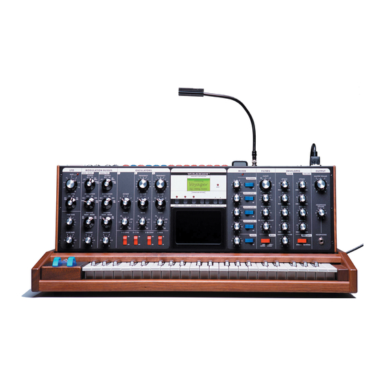
Voyager User’s Manual - The Basics Overview and Features The Voyager is a monophonic analog synthesizer that is a descendant of the classic Minimoog. Its sound sources are an external audio input, a noise source, and three analog, variable waveform oscillators. The Voyager has front panel controls for real time control of its parameters (Voyager keyboard edition shown). - Page 10 Voyager User’s Manual - The Basics RME Front Panel The RME offers the same front panel controls as Voyager Keyboard Editions., and is nearly identical in its layout, save for the Touch Surface (not offered on the RME) and a repositioned User Interface/LED Display. Page 12...
- Page 11 Voyager User’s Manual - The Basics Back Panel: The Voyager’s back panel offers connections for Power, MIDI, Control Voltage I/O and Audio I/O. For Voyag- er Keyboards, 14 CV inputs are provided on 1⁄4“ jacks. A jack with a red nut indicates a CV/Expression Pedal input, while a jack with a blue nut indicates a gate/footswitch input.
-
Page 12: Signal Flow
Voyager User’s Manual - The Basics Signal Flow To understand the Voyager’s internal signal flow, it’s helpful to consider the three types of signal routings in the system: the audio path, the control voltage path, and the modulation path. Audio Path The Voyager’s audio path includes all of the signal sources and signal modifiers that produce an audio output. - Page 13 Voyager User’s Manual - The Basics Control Voltage Path When a key is pressed, or a MIDI Note On message is received, a Gate and Pitch Control Voltage (CV) are produced. The Gate signal is used to trigger both the Filter and Volume Envelope Generators (EGs). The Pitch CV is used to determine the pitch of the Oscillators and can be applied to a varying degree to the Filters through the Keyboard Control Amount knob.
- Page 14 Voyager User’s Manual - The Basics The Modulation Buss Path Additional Modulation The Touch Surface controller can control three parameters simultaneously. The position of a finger on the touch pad generates a control voltage for the horizontal (X) position and a contorl voltage for the vertical (Y) position.
- Page 15 3. The Voyager responds to MIDI Bank Select and Program Change messages. For storage and recall of more than 896 presets, Moog Music recommends purchasing the Voyager Editor/ Librarian, a Mac/PC program designed for creating, organizing and archiving presets for the Voyager. It can be purchased from the Moog Music website (www.moogmusic.com).
-
Page 16: The Components
Voyager User’s Manual - The Components The Components Now let’s take a look at the individual module components that make up the Voyager Synthesizer, starting with the Mixer section. Then we’ll move on to the Oscillators, Filters, Envelopes, and Output Sections, the LFO and Modulation sections, the Keyboard and Left-Hand controls, the Back Panel, and the User Interface section. - Page 17 Voyager User’s Manual - The Components External: The EXTERNAL control allows an external monophonic audio source to be routed into the Mixer, where it can be mixed with the Oscillators and Noise source (an “Ext Audio In” jack on the Voyager back panel is provided for this input).
-
Page 18: Oscillator Section
Voyager User’s Manual - The Components B. The Oscillator Section The Oscillators are the main sound source of the Voyager. The oscillators in the Voyager are all analog Voltage Controlled Oscillators, or VCOs. They feature a temperature regulation circuit that provides them with excellent tuning stability. - Page 19 Voyager User’s Manual - The Components Frequency: Oscillators 2 and 3 have a FREQUENCY control. When the control is in the center position, the oscillators should be in unison with the frequency of Oscillator 1 (when the octave switches for all three oscillators are in the same position).
- Page 20 Voyager User’s Manual - The Components 3 KB Cont (Oscillator 3 Keyboard Control): The 3 KB CONT switch disables keyboard control of Oscillator 3 when in the OFF position. By disabling the keyboard control, you can use Oscillator 3 as a drone or as a modulation source whose frequency doesn’t change with the key played.
- Page 21 Voyager User’s Manual - The Components Additional CV Connections (applies to all Voyager keyboards and the RME with the VX-352 CV Input Ex- pander only): Pitch: The PITCH jack allows you to connect an external CV or expression pedal to control the Voyager’s pitch. All three oscillators are effected by this connection.
-
Page 22: Filter Section
6dB to the cutoff slope. This means that a one-pole filter has a cutoff slope of 6db/oct, a 2-pole filter has a 12dB/oct cutoff slope, etc. The classic Moog filter – the sound that started it all – is a 4-pole, 24dB/oct lowpass filter. - Page 23 Voyager User’s Manual - The Components The Voyager has two voltage controlled filters (VCF’s) that can be configured either as dual lowpass filters or as a combination of highpass & lowpass through a front panel switch. Additionally, the cutoff slope of each filter can be changed in software, resulting in a wide range of unique and interesting sounds.
- Page 24 When the SPACING control is centered, the cutoff frequencies of the two filters are identical and the filter sounds like a classic Moog Filter. Setting the SPACING control to +1 in Dual Lowpass mode means that the right filter has a cutoff frequency equal to where the CUTOFF control knob is set, and the left frequency has a cutoff frequency that is one octave higher than the right filter.
-
Page 25: Envelopes Section
Voyager User’s Manual - The Components Additional CV Connections (applies to all Voyager keyboards and the RME with the VX-352 CV Input Ex- pander only): Filter: The FILTER jack allows you to connect an external CV or expression pedal to control the filter cutoff frequency. - Page 26 Voyager User’s Manual - The Components Envelope Section Controls: Attack: The ATTACK control sets the attack time of the corresponding envelope generator, from 1 msec to 10 seconds. Decay: The DECAY control sets the decay time of the corresponding envelope generator, from 1 msec to 10 seconds.
- Page 27 Voyager User’s Manual - The Components Related Controls: Release Switch: The release time of the envelopes is set by their respective RELEASE control knob, but this control can also be switched OFF. On the Voyager keyboard , there’s a dedicated RELEASE switch located in the left-hand control panel for this.
-
Page 28: Output Section
Voyager User’s Manual - The Components E. The Output Section The Voyager has two audio outputs. There is a Voltage Controlled Amplifier (VCA) for each output, which allows for stereo functions such as panning or the dual lowpass filtering. The main control for the volume is the Master Volume control. -
Page 29: Modulation Section
Voyager User’s Manual - The Components F – The Modulation Buss Section Modulation is the heart of making interesting sounds with analog subtractive synthesis. The Voyager’s two Modulation Busses open up a world of modulation possibilities that were not available on the original Minimoog. - Page 30 Voyager User’s Manual - The Components Three controls modify the amount of modulation: the AMOUNT control, the SHAPING control, and the Mod Wheel (for the Mod Wheel Mod Buss) or MOD1 level (for the Pedal/On Mod Buss). The AMOUNT control sets how much both the Mod Wheel/MOD1 Input and the Shaping CV allow the mod source through to the mod destination.
- Page 31 Voyager User’s Manual - The Components Destination: The DESTINATION control selects the destination of the modulation. The modulation destination is cho- sen in the same manner as the source. The modulation destination selections are: - PITCH (the pitch of all three oscillators) - OSC2 (the pitch of Oscillator 2 only) - OSC3 (the pitch of Oscillator 3 only) - FILTER (the Cutoff Frequency of the filter)
- Page 32 Voyager User’s Manual - The Components Additional CV Control (applies to all Voyager keyboards and the RME with the VX-352 CV Input Expander only): MOD 1: The MOD 1 jack accepts an expression pedal or control voltage from 0 to 5 Volts. This input is used as the performance control for the PEDAL/ON Mod Bus.
-
Page 33: Lfo/Sample & Hold Section
Voyager User’s Manual - The Components G – The LFO/Sample and Hold Section The Voyager has a dedicated Low Frequency Oscillator (LFO) and Sample and Hold (S+H) function. The LFO produces triangle and square waves that oscillate from .2 to 50 Hz. Both the triangle and square wave outputs can be selected as modulation sources in the Mod Busses. - Page 34 Voyager User’s Manual - The Components LFO/Sample and Hold Section Controls LFO Rate: The LFO RATE control sets the rate of the dedicated LFO. The control range is 0.2 to 50 Hz. LFO Sync: The LFO SYNC control selects the trigger method for starting the LFO waveform. There are four trigger modes: - OFF/SYNC: This setting allows the LFO to be free running unless there is a connection to the LFO SYNC input (see below).
-
Page 35: Keyboard & Lh Controllers
Voyager User’s Manual - The Components H – Keyboard and Left-Hand Controllers The Voyager has a 44-note keyboard (3 1⁄2 octaves, F to C), just like the original Minimoog. Unlike the original, however, the Voyager has an octave transpose feature (accessed by dou- ble-pressing the EDIT button) giving it a playable range of 7 1⁄2 octaves. -
Page 36: Touch Surface Controller
Voyager User’s Manual - The Components I – Touch Surface Controller (Voyager keyboard models only) The Touch Surface Controller is a real-time, three-dimensional control surface. It can be used to impart complex gestures to the sound of the Voyager by touching it, by moving a finger around on it or by tapping it. -
Page 37: Back Panel
Voyager User’s Manual - The Components J – The Back Panel The back panel provides for all of the Voyager’s connectivity, including power, MIDI, audio and CV expansion connetions. POWER CONNECTOR: This is a standard AC power inlet, Use only a power cord designed to mate with this receptacle. The Voyager power supply is designed to work with power inputs of 100-240 VAC;... - Page 38 The CV/Expression Inputs are 1⁄4” TS jacks color coded with a red nut. These jacks accept an input from an expression pedal such as the Moog EP-2, or a CV from -5V to +5V. Note that some inputs, such as the MOD 1and VOLUME operate only from 0V to +5V, so applying a negative CV to these inputs will have no effect.
-
Page 39: Interface Panel
Voyager User’s Manual - The Components K – Interface Panel The Interface Panel, located in the top center of the instrument, provides a status display and controls for all of the Voyager’s software functions and instrument settings. Voyager Keyboard Voyager RME The status display is an LCD screen located within the Interface Panel. - Page 40 Voyager User’s Manual - The Components Enter: The ENTER button is used to enter and store all changes (presets and global), and is occasionally used as a navigation control in certain menus. Cursor: The CURSOR button is used to navigate the display and make menu selections. -1/+1: The -1/+1 buttons are used to select presets in Panel Mode, and choose functions and select parameter values in Panel, Edit and Master modes.
-
Page 41: The User Interface Panel Mode
Voyager User’s Manual - PANEL Mode Panel Mode Panel Mode is used to access presets and other performance functions. Pressing the PANEL button accesses Panel Mode. The LED above the PANEL button will be lit, and the preset name and location will be displayed. - Page 42 Voyager User’s Manual - PANEL Mode To select a Panel Mode menu function, use the -1/+1 buttons to highlight the desired function and then press ENTER. A description of the Panel Mode functions follows. In PANEL, EDIT or MASTER mode, when you reach the bottom of the menu pages, the next “-1” button press will wrap back to the top item on the first menu page.
- Page 43 Voyager User’s Manual - PANEL Mode HEADPHONE VOLUME (Keyboard Editions only): HEADPHONE VOLUME is used to determine whether the stored Head- phone Volume value is loaded when a new preset becomes active. If this is off, then this value is determined by the current position of the HEAD- PHONE VOLUME control.
- Page 44 Voyager User’s Manual - PANEL Mode RELEASE FUNCTION (RME only): This function works like the RELEASE switch on the left-hand control panel of the Voyager keyboard – it switches the Release function ON or OFF. To make a change in this menu, use the CURSOR to highlight the desired choice and press ENTER.
- Page 45 Voyager User’s Manual - PANEL Mode LCD CONTRAST The LCD CONTRAST function changes the viewable angle of the LCD display. To change this setting, use the -1/+1 buttons to adjust the contrast level. The change will immediately take effect (you’ll see the display contrast change) and the new contrast value will be stored automatically.
- Page 46 Voyager User’s Manual - PANEL Mode PANIC BUTTON (RME only): The PANIC BUTTON function allows you to program the MASTER button as a ‘panic’ button. When the PANIC BUTTON function is enabled, pressing the MASTER button issues an ‘ALL NOTES OFF’ MIDI message that silences the RME and resets the Pitch Bend and Mod Wheel controller values.
-
Page 47: Edit Mode
Voyager User’s Manual - EDIT Mode Edit Mode Edit Mode is used to assign the parameters of a preset that are not accessible through the front panel controls. Edit Mode is also used assign the preset sound category, set the MIDI clock divider, and name and save presets. - Page 48 Voyager User’s Manual - EDIT Mode Here are the Edit Mode functions: 1.1 COMPARE TO PRESET The COMPARE TO PRESET function is used to compare the current Panel sound to any other preset in the current Preset bank. Applications for this include comparing an edited version of a sound to its original version in memory, or to find a preset location that you do not use where you can store your current Panel Sound.
- Page 49 Voyager User’s Manual - EDIT Mode 1.4 PITCH BEND AMT. (PITCH BEND AMOUNT): The PITCH BEND AMT function allows you to set separate up and down pitch bend ranges for each preset. To adjust the ranges, use the CURSOR to toggle between the Pitch Bend UP and Pitch Bend DOWN parameters, and use the -1/+1 buttons to select the desired range.
- Page 50 Voyager User’s Manual - EDIT Mode 2.3 PGM PEDAL SOURCE (Programmable Pedal Source) PGM PEDAL SOURCE allows you to program one of 8 additional modulation sources to be used when the Pedal/ON Bus SOURCE control is set to ‘NOISE/PGM’. To select a source, use the -1/+1 buttons to highlight the desired selection and press ENTER.
- Page 51 Voyager User’s Manual - EDIT Mode Programmable Shaping Sources are useful for creating presets that respond in complex ways. For instance, you could assign both Keyboard CV (pitch) and Velocity Release (velocity) as the Programmable Shaping Sources. With this assignment, the higher and the harder you play, more modulation source is passed to modulate the destination.
- Page 52 Voyager User’s Manual - EDIT Mode 4.1 FIL. A POLE SEL. (Filter A Pole Select) This function allows you to specify the cutoff slope of Filter A. Filter A is the filter controlled only by the CUTOFF control. In Dual Lowpass Mode, the output of Filter A appears on the RIGHT output jack.
- Page 53 Voyager User’s Manual - EDIT Mode 5.1 T.S. DESTINATION (Touch Surface Destination): The Voyager’s Touch Surface produces four controls signals labeled X,Y, A, and Gate. The X and Y control signals are generated by touching the touch surface and reflect the left-right position and up-down position, respectively.
- Page 54 Voyager User’s Manual - EDIT Mode MIDI Control Number (MIDI CTRL NO.): The Touch Surface inputs can transmit user-selected MIDI CC Messages. For each of the X, Y and A axes, the Touch Surface Inputs can be set to transmit MIDI CCs 1-31, or it can transmit no MIDI information (OFF).
- Page 55 Voyager User’s Manual - EDIT Mode 1. The S&H Gate signal is the LFO Square Wave normalled to the S&H Gate Input connection on the VX-352. If nothing is connected to the S&H Gate Input jack, the sample rate of the TS LFO S&H function is controlled by the RME’s LFO.
- Page 56 Voyager User’s Manual - EDIT Mode TS GATE (con’t) The LFO Restart function is the fourth option in the TS Gate Con- trol menu. Since the TS Gate Control menu can only display three options at a time, use the CURSOR to scroll down to the bottom of the list, where the LFO Restart option will appear.
- Page 57 Voyager User’s Manual - EDIT Mode Source and Destination (SRC/DEST): The Source and Destination parameters allow you to select from the 40 assignable Pot Mapping Sources and Destination options. Eight of these are Performance Controls and 32 are Front Panel Controls. Both the Source and Destination have the same assignable options.
- Page 58 Voyager User’s Manual - EDIT Mode Pot Mapping is a very powerful addition to the Voyager’s front panel controls, as it creates the ability to route controls to more than one destination. A simple use is for dynamically controlling Volume with the Keyboard’s Note On Velocity, a common modulation in modern synthesizers.
- Page 59 Voyager User’s Manual - EDIT Mode 6.2 SOUND CATEGORY SOUND CATEGORY allows you to assign the current preset to one of 32 pre-defined sound categories. This function is intended to assist in organizing presets for quick identification when auditioning sounds. This is especially useful in conjunction with the Voyager Editor/Librarian software.
- Page 60 Voyager User’s Manual - EDIT Mode MIDI Note ONs can also be used to name Presets. The 44 keys on the Voyager keyboard (MIDI Note numbers 53-96) address all of the available letter, number and punctuation characters as shown below. The SHIFT key (the lower-most B flat) toggles between uppercase and lowercase characters.
-
Page 61: Master Mode
Voyager User’s Manual - MASTER Mode Master Mode Master Mode is used to access the Voyager’s global parameters and the routines sending and receiving data. Press the MASTER button to enter Master Mode. To select a Master Mode function, use the -1/+1 buttons to highlight the desired function and then press ENTER. - Page 62 Voyager User’s Manual - MASTER Mode Here are the Master Mode functions: MIDI RUN STATUS The MIDI RUN STATUS (MIDI Running Status) function is used to reduce the MIDI data sent when a number of MIDI messages with the same Status Byte are sent.
- Page 63 Voyager User’s Manual - MASTER Mode MIDI MERGE FUNC. When enabled (‘YES’), the MIDI Merge function passes incoming MIDI Note ON and Note OFF messages from the Voyager’s MIDI In jack to the MIDI Out jack. When this function is disabled (‘NO’), only MIDI events created by the instrument appear at the MIDI Out.
- Page 64 Voyager User’s Manual - MASTER Mode MIDI IN ON/OFF (Keyboard editions only) This function is used to enable (‘YES’) or disable (‘NO’) reception of incoming MIDI data. Use the CURSOR to select the desired choice and press ENTER. MIDI OUT ON/OFF This function is used to enable (‘YES’) or disable (‘NO’) transmission of outgoing MIDI data.
- Page 65 Voyager User’s Manual - MASTER Mode RECEIVE PRESETS The RECEIVE PRESETS function enables or disables System Exclusive reception on the Voyager. When enabled, the Voyager will receive all SysEx preset and bank data. When disabled, the Voyager will ignore all incoming SysEx messages.
- Page 66 Voyager User’s Manual - MASTER Mode MIDI KEY ORDER MIDI KEY ORDER allows multiple Voyagers to function together as a polyphonic synth when controlled by an external MIDI device. Up to 16 Voyagers can be linked together to create a 16-voice synth. To define the number of Voyagers in a polyphonic setup, set the MAXIMUM KEYS parameter to the number of Voyagers in your setup, then configure each Voyager for a different voice number using the ACTIVE KEY parameter.
- Page 67 Voyager User’s Manual - MASTER Mode Factory Setups Factory Setup Menus All Voyager editions (keyboards and RME) have the same Factory Setup menus, which span four pages as shown: The Voyager Factory Setup Menus Page 69...
- Page 68 Voyager User’s Manual - MASTER Mode Factory Setups 1.1 FACTORY RESET The FACTORY RESET function resets the Voyager PANEL and MASTER functions to the default factory state (see below for the list of default values). To reset the PANEL and MASTER functions select ‘YES’ and press ENTER.
- Page 69 Voyager User’s Manual - MASTER Mode Factory Setups 1.2 FACTORY SOUNDS The FACTORY SOUNDS function restores the Voyager to its default factory state. Performing this function will replace the current bank with the standard Voyager Performer Edition Preset Bank, so don’t do this unless you are sure you want to. To restore the Voyager’s factory presets select ‘YES’...
- Page 70 Voyager User’s Manual - MASTER Mode Factory Setups 2.1 T.S. XYAG S&H (Touch Surface XYAG Sample & Hold) The T.S. XYAG S&H function sets the Touch Surface LFO Sample & Hold parameter to “OFF” for all Presets in the current bank (other banks are not affected).
- Page 71 Voyager Power-on logo or the new version Power-on logo. There is no difference in performance, but the new Power- On screen displays the Moog logo and the software version. To change the appearance of the Power-on screen, use the CURSOR to select ‘YES’...
- Page 72 Voyager User’s Manual - MASTER Mode SOFTWARE VERSION The SOFTWARE VERSION screen displays the current Operating System ROM and BOOT ROM versions and date of the release. When the software version screen is displayed, pressing the CURSOR button will display the current Pitch Bend and Mod Wheel values.
- Page 73 Voyager User’s Manual - MASTER Mode RECEIVE UPDATE The RECEIVE UPDATE utility allows you to upgrade the Voyager’s Operating System. Updates are available from our website (www.moogmusic.com) and are found in Minimoog Voyager ‘Software’ section. Instruction for installing the software is provided with the files – please follow these instructions carefully! When you select RECEIVE UPDATE from the Master Mode menu and hit ENTER, the Voyager will display a message about deleting the operating system as shown.
-
Page 74: How The Voyager Handles Midi
Voyager User’s Manual - MIDI How the Voyager handles MIDI When you adjust any one of the Voyager’s front panel controls, MIDI Continuous Controller (CC) mes- sages are transmitted on the MIDI Out jack. The information contained in these MIDI messages varies according to the parameter each edit control is assigned. - Page 75 Voyager User’s Manual - MIDI SECTION CONTROL FUNCTION VALUE/RANGE MOD WHEEL Modulation 1 MSB, 33 LSB GLIDE SWITCH Turns Glide ON/OFF 0-63 OFF, 64-127 ON RELEASE SWITCH Turns Release ON/OFF 0-63 OFF, 64-127 ON MOD 1 Mod 1 Input 2 MSB, 34 LSB MOD 2 Mod 2 Input 4 MSB, 36 LSB...
- Page 76 Voyager User’s Manual - MIDI SECTION CONTROL FUNCTION VALUE/RANGE EXTERNAL (see NOTE) Adjusts the level of the external audio signal 14 MSB, 46 LSB EXTERNAL SWITCH Toggles the external audio ON/OFF 0-63 OFF, 64-127 ON OSCILLATOR 1 Adjusts the level of oscillator 1 15 MSB, 47 LSB OSCILLATOR 1 SW Toggles oscillator 1 ON/OFF...
-
Page 77: A - Touch Surface Lfo S&H: In Use
Since the TS LFO S&H function is controlled by the LFO, it means that all of the LFO SYNC control settings (MIDI, KY, ENV GATE) apply to the Touch Surface LFO S&H function as well. To download examples of Presets programmed to use the TS LFO S&H function, go to the Moog Music web site (www.moogmusic.com). -
Page 78: B - Midi Basics
Voyager User’s Manual - Appendices Appendix B - MIDI Basics MIDI is an acronym for ‘Musical Instrument Digital Interface’, an industry-standard protocol for the interconnection and control of electronic musical instruments. Prior to MIDI, instrument manufacturers designed their own systems for connecting devices together (most were CV/gate based), but few of these systems were compatible, which meant that you couldn’t easily connect synthesizers from Manufacturer A with those from Manufacturer B. - Page 79 Voyager User’s Manual - Appendices CONTINUOUS CONTROLLER: The Voyager is a knob-laden synth. Many of its controls provide smooth, continuous change over their parameters. Continuous Controller messages (abbreviated as ‘CCs’) are used to effect changes in a MIDI synth much as the knobs on an analog synth. A Continuous Controller message has a CC number (from 0-127), which is assigned to a synthesis parameter inside the receiving device.
- Page 80 Voyager User’s Manual - Appendices Appendix C - Initialization Parameters When you select the INIT PARAMETERS function in the Panel Mode menu, the current Preset sound de- faults to a single 8’ square wave oscillator with moderate filtering and basic ON/OFF envelopes. From this starting point, you can adjust and tweak the sound to create a new preset, or just explore the various param- eters to see what they do.
-
Page 81: C - Initilization Parameters
Voyager User’s Manual - Appendices Initialization Parameters (con’t) Preset Software Parameters: SECTION PARAMETER VALUE SECTION PARAMETER VALUE MAP 1 SOURCE VELOCITY PITCH BEND +/- FOURTH ATTACK AMOUNT MAP 1 DEST. MASTER KEYBOARD MODE LOWER KEY VOLUME PRIORITY MAP 1 DIRECTION NORMAL TRIGGER MODE SINGLE... -
Page 82: D - Synthesis Tutorial
Voyager User’s Manual - Appendices Appendix D - SynthesisTutorial For those who are new to the world of electronic music, let’s take a few moments to go through the basics of sound and synthesis. Sound is simply the audible change in air pressure. When we perceive sound, our ears are responding to variations in air pressure that hap- pen to occur in our range of hearing. - Page 83 Voyager User’s Manual - Appendices The Subtractive Synthesis Model The Oscillator is the starting point of Subtractive Synthesis, for it is here that the initial sound is created. The oscillator creates electrical vibrations which function in a manner similar to the strings of a guitar; they create the signal source that the rest of the system will use to modify and shape the sound.
- Page 84 Voyager User’s Manual - Appendices Like the square wave, the triangle wave only contains odd harmonics, but the levels of the harmonics in a triangle wave are much less. The triangle wave has a soft, slightly buzzy sound that is suitable for high- pitched leads (like a flute) or adding a beefy sub-bass to bass sounds.
- Page 85 Voyager User’s Manual - Appendices The Filtered signal is routed to the Amplifier, which controls the gain (volume) of the signal. The Amplifier controls the dynamics of a sound, turning it on and off as you play. The Amplifier is usually paired with an Envelope Generator (described below).
- Page 86 This is especially true of the oscillators and envelope generators, but may also be true of filters, amplifiers and LFO’s. For example, the Moog Voyager has three oscillators, two filters, two amplifiers, an LFO, two extensive modulation sections, and the Voyager’s third oscillator can act as an additional LFO. As you would expect, synthesizers that offer more than one of each component provide a broader palette for sound creation then those that don’t, and generally result in sounds with a greater complexity, variation, and...
-
Page 87: E - Midi Implementation
Voyager User’s Manual - Appendices Appendix E - MIDI Implementation Chart Moog Music, Inc. Date: 6/23/08 Voyager Analog Synthesizer Version 3.4 FUNCTION TRANSMITTED RECOGNIZED REMARKS Basic channel Default 1-16 1-16 Memorized Changed 1-16 1-16 Mode Default * Note priority is user selectable... -
Page 88: F - Service & Support Information
Music before returning any product. You can request an RMA number on-line using the ‘Product Register’ link on the Moog Music home page or call us at (828) 251-0090. The Voyager must be returned in the origi- nal inner packing including the foam inserts. The warranty will not be honored if the product is not properly packed. - Page 89 With proper conservation, you can expect your lamps to last for many years. Moog Music will be stocking replacement lamps which can be installed at the factory.
-
Page 90: H - Vx-351 & Vx-352 Cv Expanders
Voyager User’s Manual - Appendices Appendix H - VX-351 & VX-352 CV Expanders Flash back to the late 60’s: Back in the day, a synthesizer was a behemoth of panels and patch cords. They were known as modular synthesizers, because each function of the synthesizer was contained in a single module. - Page 91 Voyager User’s Manual - Appendices Connecting the VX351 and VX-352: Make all connections as described below with the Voyager powered OFF 1) If your are using the VX-351 with a Voyager keyboard, the first step is to install the VX-351 output adapter.
- Page 92 Voyager User’s Manual - Appendices This is a very basic use for the VX-351/VX-352, but it demonstrates the fundamental concept of how to use it: a source always goes to a destination. Using this fundamental concept, you can patch together additional modulations and get as complex as you like.
- Page 93 Voyager User’s Manual - Appendices This group of outputs is generated from the Voyager’s LFO. There are two CV waveforms available here (triangle and square) and both can be used at the same time TRIANGLE: This is the triangle wave output of the LFO. SQUARE: This is the square wave output of the LFO.
- Page 94 Voyager User’s Manual - Appendices The table below shows the effective ranges of the VX-351 Outputs. SECTION PARAMETER EFFECTIVE RANGE -5 to + 5V -5 to + 5V TOUCH -5 to + 5V GATE +5V ON, 0V OFF PITCH (Note 1) -0.916V to 2.667V Nominal -5 to + 5V PRESS...
- Page 95 Voyager User’s Manual - Appendices VX-352 CV Input Expander - Description The following is a description of the inputs and the functions contained in the VX-352 CV Input Expander. TOUCH This group of inputs allows you to apply an external signal to control the RME’s Touch Surface parameters. Although the RME has no Touch Surface (TS), through Edit Mode you can program the TS inputs as modulation sources for the Mod Busses, modulation shaper sources, or as sources for specific TS routings.
- Page 96 Voyager User’s Manual - Appendices This group of inputs allows you to connect an external CV or expression pedal to control the Voyager’s Volume and Pan parameters. VOLUME: This input affects the volume of both VCA’s. The Voyager’s MASTER VOLUME control sets the absolute maximum value.
- Page 97 Voyager User’s Manual - Appendices S & H IN This group of inputs allow you to connect external signals to control the Voyager’s Sample and Hold Circuit. S&H In : This is the input to the Voyager’s Sample and Hold circuit. This jack accepts an expression pedal or a control voltage from -5 to +5V.
- Page 98 Voyager User’s Manual - Appendices The table below shows the effective ranges of the VX-352 Inputs. All non-gate inputs supply power, allowing you to connect either an expression pedal or a control voltage. SECTION PARAMETER EFFECTIVE JACK RANGE SUPPLIES POWER -5 to +5V -5 to +5V TOUCH...
- Page 99 Voyager User’s Manual - Appendices Documenting your work One thing to keep in mind is that although the Voyager can remember the settings of the front panel controls as a preset, it cannot save the routings of patch cables or the positions of the attenuators. We recommend having a list of the Expander connections with space to document routings like so: Page 101...
- Page 100 Voyager User’s Manual - Appendices The following are some ways to use the VX-351 and VX-352 with the Voyager. Gather up some 1⁄4” patch cords and try these suggestions: 1. Use the Mod Wheel to control the amount of both Mod Buss signals This is a really useful way to use the Mod Wheel as a controller for more than one type of modulation.
- Page 101 Voyager User’s Manual - Appendices As a variation, switch the Pedal/On Mod Buss SOURCE to ‘ON’. Now play a note – pressing down makes the filter brighter. 4. LFO triggers Voyager’s Envelopes This is an alternative to triggering a sound from the Voyager by pressing a key. The last key pressed will determine the pitch, but the LFO will trigger the start of the envelopes.
-
Page 102: I - Using The Cp-251 With The Voyager
Voyager User’s Manual - Appendices Appendix I - Using the CP-251 with the Voyager The Moogerfooger® CP-251 Control Processor makes an ideal com- panion to the Voyager synthesizer. The CP-251 provides an LFO with two waveforms (Triangle/Square), a Sample & Hold circuit with two outputs (stepped/smooth), a Lag Processor, a Noise source, a Mixer and two active Attenuators. - Page 103 Voyager User’s Manual - Appendices To produce a modulated filter effect: Using a patch cord, connect the CP-251 Attenuator Output to the Voyager’s FILTER jack (or the FILTER CUTOFF jack on the VX-352). On the CP-251, set the LFO RATE control to 6 Hz (about 1 o’clock), and adjust the ATTENUATOR to about ‘2’...
- Page 104 Voyager User’s Manual - Appendices 4. Lag Generator used to smooth Pressure This is a way to smooth a Pressure CV signal to enhance performance expressiveness. - Initialize the Voyager’s parameters. - Using a patch cord, connect the VX-351 KBD PRESS output to the CP-251’s Lag Processor Input. - Using another patch cord, connect CP-251’s Lag Processor Output to an Attenuator Input.
- Page 105 Voyager User’s Manual - Appendices Now when you play a note, you should hear a noise component at the beginning of the note. Playing with a combination of filter envelope times, filter cutoff, noise level, and Pedal/On Mod Buss amount will make this effect more or less perceptible.
-
Page 106: J - Specifications
Voyager User’s Manual - Appendices Appendix J - Specifications Type: Back Panel: Programmable monophonic analog AC Power Inlet (universal power supply, synthesizer 100-250 VAC, 50-60 Hz) Power ON/OFF switch Sound Generation: Stereo Audio Output jacks (switch-selectable 3 Oscillators with continuously variable wave- +4 dBM, 600 ohm balanced outputs form control, 1 Noise source, 5-input Mixer, or -2dBM unbalanced outputs avail-... - Page 107 Voyager User’s Manual - Appendices Appendix K - Accessories To further enhance the functionality and appearance of the Minimoog Voyager, Moog Music offers the following optional accessories. For complete information on everything listed here, including pricing and ordering info, see your Moog dealer, or visit www. moogmusic.com EP2 Expression Pedal The EP2 Expression Pedal is the finest expression pedal available.
-
Page 108: K - Accessories
Protect your investment when you’re not using it. The water repellant dust cover (with a drawstring) keeps dust, pet hair, and other airborne debris from collecting on the Voyager. Moog Multi-Purpose Gig Bag Take your Voyager RME on the road with the utmost confidence. The multi-purpose gig bag has interchangeable velcro dividers can be configured to create one large compartment (for the RME), or many useful smaller compartments. -
Page 109: Glossary
Voyager User’s Manual - Glossary Glossary Here are a few key terms that cover the basics of sound generation as used in the Voyager synthesizer. ADSR – Abbreviation for Attack, Decay, Sustain and Release, the four stages of an envelope control voltage. - Page 110 Voyager User’s Manual - Glossary EEPROM – EEPROM stands for ‘Electrically Erasable Programmable Read Only Memory’. This is a type of digital memory used to store information, even after the power is turned off. In the Voyager, the EEPROM is used to store global settings and presets, and operating system parameters. Filter –...
- Page 111 Voyager User’s Manual - Glossary Mixer – A circuit for combining multiple sound sources or signals. Modulation – Modulation is the use of a control voltage to shape a tone. Modulation has a source, a destination, and an amount. This could be as simple as the filter cutoff of a VCF (a modulation destination) being changed by the front panel cutoff control (the source), or as complex as mixing multiple CVs together to modulate filter cutoff.
- Page 112 5-6Hz LFO triangle or sine wave signal is applied to a voltage controlled oscillator, causing the pitch to deviate slightly above and below the base frequency. Voyager – A monophonic analog synthesizer designed by Bob Moog that is a descendant of the classic Minimoog.
-
Page 113: Preset List
Mod Wheel, Touch Surface and Aftertouch for additional performance control. Credits: Bank A (designed for the Voyager Select Series) Contributors: Mike Krewitsky, Roger O’Donnel, Ben Wilson, and Moog Music Bank B (designed for the Voyager Rack Mount Edition) Contributors: Nigel Hopkins, Brian Kehew, Will Alexander and Moog Music... - Page 116 Minimoog Voyager User’s Manual © Moog Music 2008, all rights reserved Text and illustrations by Greg Kist, Steve Dunnington and the resources of Moog Music...
Need help?
Do you have a question about the Mini Voyager and is the answer not in the manual?
Questions and answers