Table of Contents
Advertisement
Quick Links
®
DR
TRIMMER/MOWER™
SAFETY & OPERATING INSTRUCTIONS
®
Models: SPRINT
, PRO, and PRO-XL SELF-PROPELLED
Serial No.
Order No.
Read and understand this manual and all instructions before operating the DR TRIMMER/MOWER.
Original Language
DR Power Equipment
Toll-free phone: 1-800-DR-OWNER (376-9637)
Fax: 1-802-877-1213
Website: www.DRpower.com
Advertisement
Table of Contents

Related Manuals for DR SPRINT PRO


Summary of Contents for DR SPRINT PRO
- Page 1 SAFETY & OPERATING INSTRUCTIONS ® Models: SPRINT , PRO, and PRO-XL SELF-PROPELLED DR Power Equipment Toll-free phone: 1-800-DR-OWNER (376-9637) Serial No. Fax: 1-802-877-1213 Original Language Order No. Website: www.DRpower.com Read and understand this manual and all instructions before operating the DR TRIMMER/MOWER.
-
Page 2: Table Of Contents
Additional Information and Potential Changes DR Power Equipment reserves the right to discontinue, change, and improve its products at any time without notice or obligation to the purchaser. The descriptions and specifications contained in this manual were in effect at printing. Equipment described within this manual may be optional. -
Page 3: Chapter 1: General Safety Rules
Keep bystanders at least 50 feet away from your work area at all times. The tips of the cutting cords on the DR TRIMMER/MOWER can throw sticks, small stones, gravel, and bits of debris over long distances at great velocity. Do not travel over loose materials such as gravel or mulch with the trimmer head spinning. -
Page 4: Operating The Mower Safely
While using the DR TRIMMER/MOWER, do not hurry or take things for granted. When in doubt about the equipment or your surroundings, stop the machine and take the time to look things over. Make sure that you have 100% control of the mower at all times. - Page 5 No list of warnings and cautions can be all-inclusive. If situations occur that are not covered by this manual, the operator must apply common sense and operate this DR TRIMMER/MOWER in a safe manner. Contact us at www.DRpower.com or call 1-800- DR-OWNER (376-9637) for assistance.
-
Page 6: Chapter 2: Setting Up The Dr Trimmer/Mower
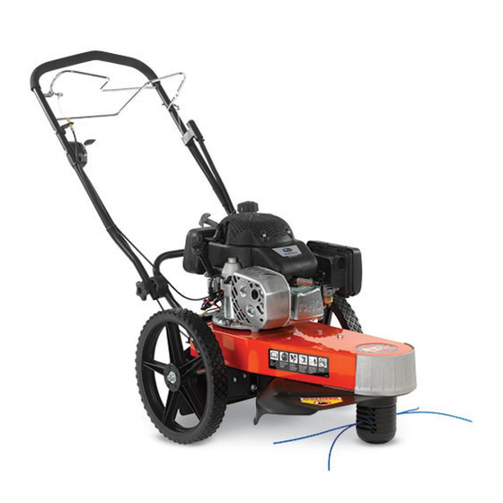
Chapter 2: Setting Up The DR TRIMMER/MOWER It may be helpful to familiarize yourself with the controls and features of your DR TRIMMER/MOWER as shown in Figure 1 before If you have any questions at all, please feel free to contact us at www.DRpower.com. -
Page 7: Specifications
75 lbs. Electric Start 77 lbs. Electric Start Unpacking the DR TRIMMER/MOWER Stabilize the shipping box at floor level in a clean flat area before attempting to unpack the Trimmer/Mower. For your safety we recommend you have two people for the following procedures. - Page 8 Top Rear 3. Use Wire Cutters to cut the Cable Ties that attach the Wheels to the Insert Handlebar and the Cable Tie that secures the Handlebar to the Box (Figure Handlebar Hand Knobs 4. Remove the Wheels, Product Package and Top Rear Insert from the Wheel Shipping Box.
- Page 9 Do not throw away your Trimmer packaging materials. Store the shipping box Figure 9 and all inserts in a dry, safe area for future use. If there are any questions contact us at www.DRpower.com or call 1-800-DR-OWNER (376-9637). Outer Lip Back-up...
- Page 10 Adding Oil and Gasoline You must add oil before starting the engine. This machine is shipped without oil. Traces of oil may be in the reservoir from factory testing, but you must add oil before starting the engine. Fill the reservoir slowly, checking the level frequently to avoid overfilling.
-
Page 11: Adjusting The Handlebar
Adjusting the Handlebar Upper Handlebar Adjustment It is important to find a Handlebar height that allows the Mow-Ball Support to Lower Handlebar Knob glide along the ground and remain balanced so you do not have to push down or pull up on the Handlebar. Bolt At the proper height, your hands should rest at a comfortable level and the front end of the Trimmer should glide easily on the Mow-Ball... -
Page 12: Chapter 3: Operating The Dr Trimmer/Mower
3. Grasp the Recoil Starter Handle (Figure 1 on page 6) and slowly pull until you feel resistance. Let the cord retract a little bit, then pull the cord rapidly to start the Engine. One or two pulls usually starts the DR TRIMMER/MOWER. It may be necessary to repeat the priming operation if the machine does not start within two pulls. -
Page 13: Engaging The Trimmer Head
Using the PTA™ (Parallel Trimming Action) - SPRINT and PRO models only Your DR TRIMMER/MOWER’S PTA feature allows you to move the machine in a straight line while the Trimmer Head is both pivoted and tilted to the left for better access to fence lines and other obstacles. PTA allows you to trim in difficult areas without having to pull the machine back and forth. -
Page 14: Engaging The Pta
Cutting Cords also tilt slightly in PTA mode so you can edge and trim along gardens, paths, and driveways (Figure 16). When using PTA along garden edges, fences, and buildings, we recommend making your first pass with the DR TRIMMER/MOWER in the Normal mowing position, staying 4 to 8 inches from the obstacle;... -
Page 15: Installing Cords
Installing Cords In Here In Here Reference Figures 21–23 for Cord installation. Your DR TRIMMER/MOWER shipped from the factory with the Cords installed in this manner. When using PTA™, install the cutting cords in one of the bottom four line plates. -
Page 16: Adjusting The Cutting Height
Cord Tips We ship two (2) thicknesses of Cutting Cord with your DR TRIMMER/MOWER. The Cords are Blue (175-mil) and Green (155-mil). Because conditions and vegetation vary so much, you should experiment with Cord weights (diameters) to discover what works best for your particular mowing and trimming situations. Here are a few things to keep in mind: ... - Page 17 Obstacle Tips Dealing with obstacles in the terrain is easy with your new DR TRIMMER/MOWER. The following section explains how to approach most common obstacles. The trimmer engine's power can easily throw stones, sticks, and other debris at great velocity, which could cause personal injury or property damage.
- Page 18 Windrows The DR TRIMMER/MOWER Cutting Cords cut even tall grass in just one pass, so you can collect clippings and leaves for mulch without raking. The machine ejects cut material to its right side, so you can use it like a lawn broom to make windrows for easy clean-up.
-
Page 19: Chapter 4: Maintaining The Dr Trimmer/Mower
Removing the Mow-Ball ™ Support Assembly Frame Tools and Supplies Needed: Head Locking Tool (supplied with your DR TRIMMER/MOWER) or a #3 Phillips head Screwdriver with at least a 6" shank Gloves 1. Insert the Head Locking Tool or Screwdriver into the hole in the Frame, then rotate the Mow-Ball™... - Page 20 2. Looking down at the top of the Frame, turn the Mow-Ball™ Support Assembly clockwise until it unscrews completely from the Bearing Housing (Figure 30). Remove the Tool or Screwdriver after you have removed the Mow-Ball™ Support Assembly. ™ NOTE: If the Mow-Ball Support Assembly continues to turn, but does not come off, check to be sure that you locked the Head Locking Tool or Screwdriver into the shaft.
- Page 21 Remove Screws Tool needed: 3/8" Wrench 1. Remove the screws on either side of the Stone Guard and drop it from the Frame (Figure 32). Tip: Keep the screws together with the Stone Guard. Removing and Replacing Section: Bottom Shield - SPRINT and PRO Models Figure 32...
- Page 22 (5) minutes to allow parts to cool and disconnect the spark plug wire, keeping it away from the spark plug. Figure 34 Lower Bearing Use only DR belts on your machine. Do not use hardware store variety belts. Housing Plate Engine Pulley Tools and Part needed:...
- Page 23 Engine Pulley. The Transmission Housing is spring loaded so it will return to its original position when released. 5. Install a new DR Drive Belt around the upper Engine Pulley, rotate the Transmission Housing out, and slip the Drive Belt around the Transmission Pulley.
- Page 24 Tools needed: Actuator 3/8" Socket 7/16" Wrench 1/2" Wrench 1. Remove the Mow-Ball™ Support Assembly. See “Removing the Mow-Ball™ Support Assembly” on page 19. 2. Remove the Stone Guard Flap. See “Removing the Stone Guard Flap” on Lock Nut page 20.
- Page 25 Wheels - SPRINT and PRO Models Remove Locknut Before performing any adjustment, maintenance procedure or inspection, stop the engine, wait five (5) minutes to allow parts to cool and disconnect the spark plug wire, keeping it away from the spark plug. Tool needed: ...
- Page 26 Adjusting the Wheel Clutch – PRO-XL SELF-PROPELLED Model If the SELF-PROPELLED DR TRIMMER/MOWER will not drive forward when you squeeze the Wheel Clutch Lever or if the machine moves forward without the operator squeezing the Wheel Clutch Lever (or the machine “walks”), you will have to adjust the Wheel Clutch Cable.
- Page 27 If the machine will not drive forward: Grasp the Lower Section of the Cable Adjuster with one hand and hold firmly. Turn the Upper Section of the Cable Adjuster clockwise so that the Adjuster is lengthening or turning apart. Make one revolution of the Adjuster at a time until the drive engages and disengages properly (Figure 48).
-
Page 28: Charging The Battery
Operate the Trimmer Engine for at least 45 minutes to maintain proper Battery charge. If the Battery loses its charge, you will need to use a trickle Charger (like the DR Battery Charger) to recharge it. The Charger should have an output of 12 volts at no more than 2 amps. - Page 29 Never store the DR Trimmer/Mower with fuel in the fuel tank inside a building where ignition sources are present, such as hot water and space heaters, clothes dryers and the like. If you are going to drain the fuel tank, do this outdoors. Allow the engine to cool before storing in any enclosure.
- Page 30 If your DR TRIMMER/MOWER will be idle for more than 30 days, we recommend using a gas stabilizer. This will prevent sediment from gumming up the Carburetor. If there is dirt or moisture in the gas or Tank, remove it by draining the Tank.
-
Page 31: Chapter 5: Troubleshooting
Spark Plug hole and pull the Recoil Cord several times to blow out any oil in the Cylinder, then wipe off the Spark Plug and reinsert it. If the Engine still will not start, visit our web site at www.DRPower.com or call 1-800-DR- OWNER (376-9637) for assistance. - Page 32 45 minutes at a time, the Battery may need to be periodically charged. See the Battery Care section on page 29. If your Battery is charged and your DR TRIMMER/MOWER still won’t start, visit our web site at www.DRPower.com or call 1-800-DR-OWNER (376-9637) for assistance.
- Page 33 Trimmer Head Belt Tension through the Trimmer Control Cable” on page 28. Check the Brake for excessive wear and replace if necessary. (See page 23) If none of the above helps, visit our web site at www.DRPower.com or call 1-800-DR- OWNER (376-9637) for assistance.
- Page 34 If they freewheel backwards, the Drive Wheel Clutches may have failed. Call 1-800-DR-OWNER (376-9637) for assistance. If none of the above helps, visit our web site at www.DRPower.com or call 1-800-DR- OWNER (376-9637) for assistance.
- Page 35 Notes: CONTACT US AT www.DRpower.com...
-
Page 36: Chapter 6: Parts Lists, Schematic Diagrams And Warranty
Chapter 6: Parts Lists, Schematic Diagrams And Warranty Parts List - Handlebar Assembly - SPRINT and PRO Models NOTE: Part numbers listed are available through DR Power Equipment. Ref# Part# Description Ref# Part# Description 143661 Knob, Handlebar, 5/16"-18 143971 Cable, Throttle, Reverse Throw, B&S... - Page 37 Schematic - Handlebar Assembly - SPRINT and PRO Models 061213 CONTACT US AT www.DRpower.com...
- Page 38 Parts List - Axle Assembly - SPRINT and PRO Models NOTE: Part numbers listed are available through DR Power Equipment. Ref# Part# Description 112381 Washer, Flat, 1/4", ZP 110761 Nut, Nylon Locking, 5/16"-18 151401 Bolt, 1/4"-20 x 3/4", Tri-Lobe (PRO,...
- Page 39 Schematic - Axle Assembly - SPRINT and PRO Models 050919 CONTACT US AT www.DRpower.com...
- Page 40 Parts List - Main Frame Assembly - All Models NOTE: Part numbers listed are available through DR Power Equipment. Ref# Part# Description Ref# Part# Description 112381 Washer, Flat, 1/4", USS PRO-XL SELF-PROPELLED Model 110761 Nut, Nylon Locking, 5/16"-18 ?????? Engine, 6.75 TQ, B&S, E/S 110731 Nut, Nylon Locking, 1/4"-20...
- Page 41 Schematic – Main Frame Assembly - All Models 061212 CONTACT US AT www.DRpower.com...
- Page 42 Parts List - Handlebar Assembly – PRO-XL SELF- PROPELLED NOTE: Part numbers listed are available through DR Power Equipment. Ref# Part# Description Ref# Part# Description 143971 Cable, Throttle, Reverse Throw, B&S 190471 Grip, Handlebar, Textured Vinyl, 18-3/4" Long 112381 Washer, Flat, 1/4" USS 143931 Spring, C, .720"...
- Page 43 Schematic - Handlebar Assembly – PRO-XL SELF- PROPELLED 061213 CONTACT US AT www.DRpower.com...
- Page 44 Parts List - Axle Assembly – PRO-XL SELF- PROPELLED NOTE: Part numbers listed are available through DR Power Equipment. Ref# Part# Description Ref# Part# Description 190541 Sleeve, Axle 189591 Spring, Ext., Transmission Tension 110761 Nut, Nylon Lock, 5/16"-18 179631 Bracket, Anti-Rotation 110731 Nut, Nylon Lock, 1/4"-20...
- Page 45 Schematic - Axle Assembly - SELF- PROPELLED 080513 CONTACT US AT www.DRpower.com...
- Page 46 Parts List - Mow Ball™ Assembly - All Models NOTE: Part numbers listed are available through DR Power Equipment. Ref# Part# Description Ref# Part# Description 112371 Washer, Flat, #10 USS 235151 Plate, Line Spacer 213081 Bolt, Flat Head, 5/16"-18 x 2.75" w/Patch...
- Page 47 Schematic – Mow Ball™ Assembly - All Models 080513...
- Page 48 Notes:...
- Page 49 Notes:...
- Page 50 Notes: 7 5 M E I G S R O A D , P . O . B O X 2 5 , V E R G E N N E S , V E R M O N T 0 5 4 9 1 ©2010 Country Home Products, Inc.
- Page 51 For the purposes of all the above warranties, “ordinary and normal consumer use” refers to non-commercial residential use and does not include misuse, accidents or damage due to inadequate maintenance. DR Power Equipment certifies that the DR TRIMMER/MOWER is fit for ordinary purposes for which a product of this ...
- Page 52 Before performing any maintenance procedure or inspection, stop the engine, wait five (5) minutes to allow all parts to cool. Disconnect the spark plug wire, keeping it away from the spark plug. To help maintain your DR TRIMMER/MOWER for optimum performance, we recommend you follow this checklist each time you use your machine.
Need help?
Do you have a question about the SPRINT PRO and is the answer not in the manual?
Questions and answers