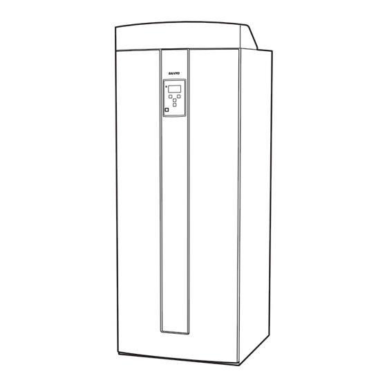
Sanyo SHP-TH90GDN-SW Technical Manual

Sanyo SHP-TH90GDN-SW Technical Manual

Natural refrigerant heat pump water heater, tank unit, heat pump unit
Table of Contents

Advertisement

http://waterheatertimer.org/Review-GE-Heat-Pump-water-heater.html
Technical Manual for Servicing
SHP-TH90GDN-SW / SHP-TH90GEN-SW / SHP-TH90GHN-SW
Shp-C90Gdn / SHP-C90GEN
RoHS
WARNING
RoHS
SANYO ELECTRIC CO., LTD
2008.10

Table of contents

....................................... 2
.................................... 5
....................................... 25
.................................... 27
................................. 28
........................... 33
.................. 55
............................................. 68
RoHS

Advertisement

Table of Contents
loading

Summary of Contents for Sanyo SHP-TH90GDN-SW

  • Page 1 Technical Manual for Servicing SANYO ELECTRIC CO., LTD SHP-TH90GDN-SW / SHP-TH90GEN-SW / SHP-TH90GHN-SW SHP-C90GDN / SHP-C90GEN 2008.10 Table of contents ………………………………… 2 ……………………………… 5 ………………………………… 25 Tank Unit ……………………………… 27 …………………………… 28 ……………………… 33 ……………… 55 ……………………………………… 68 Heat Pump Unit...
  • Page 3 2. Water heater system chart...
  • Page 5 01. Introduction Welcome Congratulations! You are now the owner of a Sanyo CO2 ECO, an electric boiler which we hope will be very much to your satisfaction. If you use and maintain the Sanyo CO2 ECO correctly you will enjoy your boiler for many years.
  • Page 6 02. Main functions The main functions of the boiler is described below. - the boiler contains an electronic control system that supervise all functions of the product, and allow you to make personal settings for a comfortable indoor climate. - room sensor gives continuously information to the control system. Necessary adjustments of the temperatures to the radiator systems are then made.
  • Page 7 Load circulating pump Draining valve Circulates the water Drains the tank unit and the between the tank unit and radiator system. the Sanyo heat pump Shut off valve (circulating pump) Must be open when the heat pump is connected. Close when circulating...
  • Page 8 Display panel Status diod Display Green light: The Graphic display, product is in normal back ground lighted. operation. Gives 8 rows of Red flashing light: information. The product needs attention. See message in the display. OK button With this button you Step back button confirm a value or a You step back to the...
  • Page 9 04. Adjustments and handling General information Sanyo CO2 Eco has a modern digital control system, with few buttons and clear text on the display, that makes the adjustments and handling logical and easy to understand. The function of the product is constantly monitored by the controls. If the operating data does not correspond with the allowed values, the product is automatically secured.
  • Page 10 Main standard settings The boilers control system is provided with standard settings. At start-up the main functions of the product operates as follow: , without heat pump unit (works like an electric boiler). - 12 kW electrical power - Operation without room sensor - Operation without room temperature decrease during nights - Values for a mid temperature radiator system - Langua...
  • Page 11 Menu explanations The MAIN MENU display Display: Explanation CO2 ECO This is the normal display of the control system, and shows the most SANYO important values in the system. ROOM (20,5c) 20,3°c TANK TEMP 47°c ROOM 35°c (20): shows the room temperature if the room sensor is OUT TEMP 13°c...
  • Page 12 The DIAGNOS MENU display Display: Explanation COMPR SPEED 60Hz General: Values within this menu can not be changed. They shows the EL HEATER UPPER 4,5 kW actual conditions in the system. Values inside the brackets is the EL HEAT TEMP UP (52) 50°c wanted values or set values.
  • Page 13 The SETTING MENU display Display: Explanation LANGUAGE General: system temperatures, desired night temperatures, main fuse etc. In this menu HEAT PUMP the settings for the radiator system is made. Night temperature set back can also be HEAD FUSE programmed here. Discuss the settings with your installer. It is of high importance that DELAY EL HEATER the radiator temperatures are correct adjusted, otherwise the savings from the heat EL HEAT TEMP UP...
  • Page 14 Example 1: 22 means that the temperature increases at 6 in the morning and decreases at 22 in the evening. Example 2: 6 12 17 22 means that the temperature increases at 6 in the morning, decreases at 12, increases at 17 and decreases at 22 in the evening.
  • Page 15 05. The temperature need for the house (Curve Inclination and curve adjust) General information The setting of the temperature need for the house is a central part of the boilers control system, be st that setting that tells the control system how much temperature your specific house need at different out door temperatures.
  • Page 16 Examples of curves Below you find two diagrams, where you can see how the curve changes at different settings. The inclination of the curve tells how much the temperature to the radiators changes at different outdoor temperatures. A lower outdoor temperature automatically gives a higher temperature to the radiators.
  • Page 17 Adequate basic settings Use this adequate basic settings after the installation ow the specific values for the house. Type of system CURVE INCL CURVE ADJUST Floor heating system only: 35°C 0°C Low temperature system: 40°C 0°C Normal temperature system: 50°C 0°C High temperature system (elderly houses, small radiators,...
  • Page 18 07. The structure of the menus...
  • Page 19 08. Maintenance General information After the installation; check together with the installer that everything work correctly. Let the installer show you buttons, valves, pressure release valves and fuses so you know how to maintenance your new boiler. Vent the air after a couple of days from the system, and if necessary, fill with more water. Pressure release valve Check the pressure release valves for domestic water and boiler water every four times a year by turn the knob on th...
  • Page 20 Draining and shut off valves The boiler shall be disconnected from voltage when draining. The draining valve for the radiator system is placed behind the plastic front panel. When draining the whole system, set the mixing valve to full open position (maximum counter clockwise).
  • Page 21 09. If errors occur General information The Sanyo CO2 Eco is constructed for high comfort, good reliability and long life length. Below you find hints how to solve different problems if they occur. If something goes wrong, contact your installer that was responsible for the installation.
  • Page 22 automatically be disconnected. Especially one phase power sources in the house e.g. engine heater for the car, coffee machine, or a washing machine, dryer or cooking place may make the boiler to be power reduced. Temperatures on radiators or sanitary hot water may be too low. T splay shows if the boiler is power reduced.
  • Page 23 Errors messages from the heat pump: (H01 H27) If an error occurs,cut off Power supply once, and please run again. But if an error occurs again, please call service. (Write the error message down.) Status messages: Status messages are shown in the normal display window. WITHOUT HP: the tank is operated without heat pump.
  • Page 27 Characteristics SHP-C90GDN SHP-C90GEN H P W A T E R O U T H P W A T E R I N...
  • Page 28 Trouble display table First check the details of the trouble display, and then be absolutely sure to turn off the power. <Tank unit> Display Trouble Criteria and diagnosis SENSOR Primary flow sensor trouble Open-circuit or short-circuit in sensor itself or lead wires PRIMARY FLOW <Diagnosis>...
  • Page 29 Trouble display table <Heat pump unit> Display Trouble Criteria and diagnosis Trouble in coil temperature sensor Open-circuit or short-circuit in sensor itself or lead wires of heat pump unit <Diagnosis> Trouble in compressor temperature • Defective contact of connector or defective crimping of sensor terminal •...
  • Page 30 Display Trouble Criteria and diagnosis HIC trouble confirmed after 8 retries <Diagnosis> • HIC protection activated by abnormal current or temperature • Blocked refrigerant circuit pipe • Instantaneous power failure caused by lightning Trip input (HIC current or • Defective HIC or outdoor fan motor shutdown temperature) •...
  • Page 31: Displaying The Error History

    The error screen is displayed by returning the tank unit’s display to the initial screen. The display alternates between the initial screen and error display screen every 4 seconds while an error is displayed. <Initial screen> CO2 ECO SANYO TANK TEMP OUT TEMP STATUS <Error screen for tank unit>...
  • Page 32: Troubleshooting Procedures

    Troubleshooting procedures 1. H05 (Trouble in high pressure switch) This trouble is confirmed after repeated 8 retries when the refrigerant pressure has exceeded the pressure setting. [Checkpoints] Is the circulation pump locked? Is any air trapped in the connecting pipes between the heat pump unit and tank unit? Has water been poured into the tank unit? Have you forgotten to open the tank unit's shut-off valves? [Remedial action]...
  • Page 33 The Sanyo CO2 Eco is a complete heat pump system that warms both the house and the hot water. The Sanyo CO2 Eco is equipped with a motorized mixing valve which constantly ensures that a correct and even temperature reaches the radiators.
  • Page 34 General information Upon delivery and installation carefully check the following important points: ck the product and check before installation that it has not been damaged during transport. Report eventual transport damage to the transporters. yo CO2 Eco must be transported in upri When moving the tank unit to the inside of the house, it can temporarily be laid down on its back.
  • Page 35 Tank unit name: SHP-TH90GDN-SW Dimensions without packaging HxWxD: 1574x596x630 mm Dimensions with packaging HxWxD: 1736x700x747 mm Electrical data: 3phase 400V Electrical heater power: Upper electrical heater power in steps: 0 1,5 3 4,5 6 7,5 9 kW Lower electrical heter power in steps:...
  • Page 36 With packaging 17 3 6 1 5 7 4 7 6 7 7 0 0 6 3 0 5 9 6...
  • Page 37 Water from heat pump unit to tank unit Water from tank unit to heat pump unit All system connections Plastic top cover. Pull on top of the tank unit and lift to remove Electrical cable inlet Top insulation of tank unit Control panel Domestic hot water coil...
  • Page 38 General information The installation must be carried out in accordance with local regulations. The boiler must be connected to an expansion vessel in an open or closed system. Carry out installation adjustments in accordance with the descriptions in Chapter 10 rt-up starting up the equipment.
  • Page 39 Operation without heat pump Sanyo CO2 Eco can be started without the heat pump being installed. The product works then like a common electric boiler with full function of the regulation. Make sure the heat pump is blocked in the control system, see User Manual.
  • Page 40 Circulation pump radiator system The circulation pump must be mounted on the primary flow of the boiler and is electrically connected from the boiler, se Electric installation . Pressure release valve for the boiler A pressure release valve for the boiler is factory mounted. The waste pipe has to be connected to a drain gutter directly, or if the distance is more than 2 m, to the waste funnel.
  • Page 41 Different systems may look different, e.g. single or double pipe systems, which can make the final installation to be different. 01 Sanyo CO2 Eco 02 Mixing valve, automatized 03 Circulation pump, radiator system...
  • Page 42 -current sensor, -outdoor sensor, -room sensor, -primary flow sensor and -external limiter. Supply Sanyo CO2 Eco shall be connected to 40 15,132 kW Main switch A main switch with at least 3 mm contact distance must be installed before the boiler.
  • Page 43 Connection of the current sensors The three current sensors, one for each phase, are installed inside the group fuse central as follows: Every phase from the electricity meter feeding the electricity group central unit is led through a current sensor before being fitted on the respective bar. Wiring to the boiler is done according to the picture on the terminal block.
  • Page 44 Outdoor sensor The sensor must be placed in the most suitable place on the wall of the house facing north-west or north to avoid exposure to the morning sun. Protect the sensor from the sun if there is a risk the sensor will be affected by it. The sensor must be placed on about 2/3 height of the wall.
  • Page 45 Power supply 400V 3N Information Installation of: Common Current sensors. Sensor 1 Connection of 1, 2 and 3 can be mixed (no Sensor 2 importance) Sensor 3 Primary flow sensor. Free polarity of cables Outdoor sensor. Free polarity of cables RG-4 Room sensor.
  • Page 46 RG-4 Room sensor. RG-2 RG-4 are the marked poles inside the RG-1 room sensor housing. Night temp / External control. See description. Black (5) Mixing valve position switch. Black (4) Factory mounted. Neutral Blue Mixing valve signal. Black (open) Factory mounted. Brown (close) Radiator circulation pump Communication with heat pump...
  • Page 47 Room sensor The room sensor must be centrally placed in the most open place in the house to enable it to feel the average temperature. E.g. in the hall between many rooms or central in the stair case. Draw a 3-leader cable (min 0,5 mm2) between the boiler and the room sensor.
  • Page 51 400V 3N...
  • Page 52 230V 1N...
  • Page 53 General information Please note! The Sanyo CO2 Eco can be connected and started without the room sensor and current sensors or heat pump being installed. The room sensor is always recommended to be installed. If the current sensors are chosen not to be installed, the internal sequence steps of the electrical heater will not be optimized.
  • Page 54 Press the Press the Later check-ups...
  • Page 55: Installation Procedure

    85264190461002 For natural refrigerant Installation Instructions heat pump water heater SHP-C90GDN (heat pump unit) SHP-C90GEN Our advice to installer • The installation work must be done correctly in order to derive the maximum from the product’s functions and performance and to ensure safety. Prior to proceeding with the installation, read through the section entitled “...
  • Page 56 IMPORTANT ! Please read before starting The safety issues indicated in these instructions fall into the category of a WARNING or CAUTION. WARNING: This indicates the possibility of death or serious injury for the installer if mistakes have been made in carrying out the work or for other individuals if trouble occurs as a result of the installation work.
  • Page 57 CAUTION Set the power supply circuit breaker Do not sit on the unit or apply force to to OFF before proceeding with the the pipes. power supply work. • An accident may occur or you may Prohibited. Do this! • Otherwise, you may receive an electric burn yourself as a result.
  • Page 58 Checking the parts packed with the unit Name of part Shape Quantity Installation instructions rubber Outline drawings 4-Ø13 47.5 400 375 ( 30 ) 1235 A (outlet) B (inlet)
  • Page 59 1. Selecting the installation location and restrictions on installation 1-1 Selecting the installation location Select a location which will ensure that the restrictions on installation described in 1-2 will be complied with. Also, make the selection while giving due consideration to providing enough space (for removing the front panel, etc.) for subsequent servicing and repairs.
  • Page 60 1-2 Restrictions on installation (1) Installation restrictions for heat pump unit (View as seen from above) 100 mm or more 100 mm Heat pump unit or more Front panel 300 mm or more Heat pump unit 100 mm or more Front panel 300 mm or more...
  • Page 61 2. Installing the heat pump unit 2-1 Installing the heat pump unit Use a stand, etc. to install the unit outdoors. Do not install it directly on the ground: otherwise, the water will not drain off easily. • Be absolutely sure to install the unit on a flat, level surface. •...
  • Page 62 3. Piping work 3-1 Standard piping diagram Pipe connections between the tank unit and heat pump unit Connect A and A (hot water pipe). Connect B and B (cold water pipe). B circulation outlet port (cold water) A circulation return port (hot water) Heat pump unit Tank unit...
  • Page 63 4. Electrical work 4-1 Precautions • Use the prescribed power supply circuit breaker and cable thickness (see table below). • Be absolutely sure to have the electrical work done by a qualified electrician. • Be absolutely sure to have the equipment grounded by a qualified electrician. (Leave a distance of at least 2 m from the ground of a lightning rod.) 4-2 Lead-in wiring work The figure below shows how the circuit is configured from the Distribution board to the hot water heater.
  • Page 64 < > SHP-C90GDN : POWER SUPPLY 400V 3N ~ 4-3 Electrical wiring connections to heat pump unit Connect the heat pump unit and tank unit as follows. POWER SUPPLY 400V 3N terminal block of HP terminal block of Tank (1) Be absolutely sure to connect the L1, L2, L3, N terminals on the tank unit with its respective terminal on the HP unit (L1-L1, L2-L2, L3-L3, N-N).
  • Page 65 < > SHP-C90GEN : POWER SUPPLY 230V ~ 4-3 Electrical wiring connections to heat pump unit Connect the heat pump unit and tank unit as follows. POWER SUPPLY 230V terminal block of Tank terminal block of HP (1) Be absolutely sure to connect the L1, N terminals on the tank unit with its respective terminal on the HP unit (L1-L1, N-N).
  • Page 66 5. Preparing for operation The steps described in this section must be taken without fail in order to confirm whether the piping work has been completed correctly. 5-1 Supplying the water (1) Fill the tank unit with water. (2) Drain off some water to remove air from the heat pump unit. (3) Check that no water is leaking from the pipe connections.
  • Page 67: Troubleshooting

    Post-installation inspections (checklist) Checkpoint Yes/No Have the installation restrictions on the heat pump unit been met? (See pages 5 and 6) Has enough space been provided for maintenance around the heat Installation work pump unit? Is the outside of the heat pump unit marked, scratched or deformed? Have copper pipes been used for the heat pump pipes? Is the pipe length within 15 meters with no more than 6 bends? Is the vertical interval of the pipe within 3 meters? Is the tube-shaped...
  • Page 71 SHP-C90GDN...
  • Page 74 SHP-C90GEN...
  • Page 75 ATTENTION ! To ensure correct parts supply,please let us know followings, when you make service parts order: SHP-C90GEN 1.Part No. 2.Description 3.Q'ty 4.Volts-Hz-Ph 5.Product Model No. OUTDOOR UNIT Part No. Description Q'ty Reference No. 623 307 0001 Magnetic Coil HPV-MOAI056B1 1FA-4-L8A0-45400 623 306 9999 Wire K 8FA-0-5286-34600...
  • Page 76 623 308 9720 Pad Corner 852-6-3609-29800 NOTE: Metal and plastic parts will be supplied basically with necessary heat insulation pads or packing. Each key number with an asterisk (*) means the recommended service parts. SANYO Electric Co.,Ltd Osaka, Japan 9/08 Printed in Japan...

This manual is also suitable for:

Shp-th90ghn-swShp-th90gen-swShp-c90gdnShp-c90gen

Table of Contents