Table of Contents
Advertisement
This publication, including photographs, illustrations and software, is under the
protection of international copyright laws, with all rights reserved. Neither this
guide, nor any of the material contained herein, may be reproduced without the
express written consent of the manufacturer.
The information in this document is subject to change without notice. The manufac-
turer makes no representations or warranties with respect to the contents hereof
and specifically disclaims any implied warranties of merchantability or fitness for
any particular purpose. Further, the manufacturer reserves the right to revise this
publication and to make changes from time to time in the content hereof without
obligation of the manufacturer to notify any person of such revision or changes.
Trademarks
IBM, VGA, and PS/2 are registered trademarks of International Business Machines.
AMD, Athlon 64 Sempron are registered trademarks of Advanced Micro Devices
Inc.
Microsoft, MS-DOS and Windows 2000/XP/Vista are registered trademarks of
Microsoft Corporation.
Award is a registered trademark of Phonex Award.
Other names used in this publication may be trademarks and are acknowledged.
Static Electricity Precautions
1. Don't take this motherboard and components out of their original static-
proof package until you are ready to install them.
2. While installing, please wear a grounded wrist strap if possible. If you
don't have a wrist strap, discharge static electricity by touching the bare
metal of the system chassis.
3. Carefully hold this motherboard by its edges. Do not touch those compo-
nents unless it is absolutely necessary. Put this motherboard on the top of
static-protection package with component side facing up while installing.
Pre-Installation Inspection
1. Inspect this motherboard whether there are any damages to components
and connectors on the board.
2. If you suspect this motherboard has been damaged, do not connect power
to the system. Contact your motherboard vendor about those damages.
Motherboard User's Guide
Copyright © 2007
All Rights Reserved
A15G Series, V1.0
November 2007
i
Advertisement
Table of Contents

Related Manuals for PC Chips Motherboard


Summary of Contents for PC Chips Motherboard
-
Page 1: Static Electricity Precautions
3. Carefully hold this motherboard by its edges. Do not touch those compo- nents unless it is absolutely necessary. Put this motherboard on the top of static-protection package with component side facing up while installing. -
Page 2: Table Of Contents
Trademark ......................i Chapter 1: Introduction ..................1 Key Features ........................1 Package Contents ......................4 Chapter 2: Motherboard Installation .............. 5 Motherboard Components .................... 6 I/O Ports .......................... 7 Installing the Processor ....................7 Installing Memory Modules ..................8 Jumper Settings ...................... - Page 3 Motherboard User’s Guide Notice: 1. Owing to Microsoft’s certifying schedule is various to every supplier, we might have some drivers not certified yet by Microsoft. Therefore, it might happen under Windows XP that a dialogue box (shown as below) pops out warning you this software has not passed Windows Logo testing to verify its compatibility with Windows XP.
-
Page 4: Chapter 1 Introduction
6/8-channel (optional) line-out. Onboard USB header(s) can provide extra ports by connecting the Extended USB Module to the motherboard. This motherboard is a Micro ATX size motherboard and has power connectors for an ATX power supply. Key Features... - Page 5 Motherboard User’s Guide Memory Support Two 240-pin DIMM slots for DDR2 SDRAM memory modules • Supports Dual Channel DDR2 800/667/533/400 memory bus • Maximum installed memory is 16* GB • (* Duo to the DRAM maximum size is 2 GB at present, the memory maximum size we have tested is 4 GB.)
- Page 6 Compliant with Universal Serial Bus Specification Revision 2.0 • Compliant with Open Host Controller Interface Specification Revision 1.1 • BIOS Firmware This motherboard uses Award BIOS that enables users to configure many system features including the following: Power management • Wake-up alarms •...
-
Page 7: Package Contents
One diskette drive ribbon cable (optional) One IDE drive ribbon cable The Software support CD Optional Accessories You can purchase the following optional accessories for this motherboard. The Extended USB module The Serial ATA cable The Serial ATA power cable... -
Page 8: Chapter 2 Motherboard Installation
Chapter 2: Motherboard Installation Chapter 2 Motherboard Installation To install this motherboard in a system, please follow these instructions in this chapter: Identify the motherboard components Install a CPU Install one or more system memory modules Make sure all jumpers and switches are set correctly... -
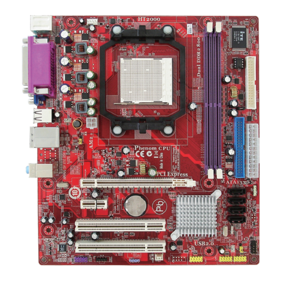
Page 9: Motherboard Components
Motherboard User’s Guide Motherboard Components ITEM LABEL COMPONENTS Socket AM 2+/AM 2 for AM D Phenom /Athlon CPU Socket X2 Dual-Core/Athlon 64/Sempron processors DIM M 1~2 240-pin DDR2 SDRAM slots Floppy disk drive connector PWR1 Standard 24-pin ATX power connector... -
Page 10: I/O Ports
Use these audio jacks to connect audio devices. The Aport is for stereo Line-In signal, w hlie the C port is for microphone in signal. The motherboard supports 8-channel audio devices that correspond to A, B, D and E port respectively. In addition, all of the three ports, A, B and D provide users w ith both right &... -
Page 11: Installing The Processor
Motherboard User’s Guide Installing the Processor This motherboard has an AM2+/AM2 processor socket. When choosing a proces- sor, consider the performance requirements of the system. Performance is based on the processor design, the clock speed and system bus frequency of the processor, and the quantity of internal cache memory and external cache memory. -
Page 12: Installing Memory Modules
Chapter 2: Motherboard Installation Installing Memory Modules This motherboard accommodates two 240-pin DIMM sockets (Dual Channel Memory Module) for unbuffered DDR2 800/667/533/400 memory modules (Double Data Rate SDRAM), and maximum 16* GB installed memory. Over its predecessor, DDR2-SDRAM offers greater bandwidth and density in a smaller package along with a reduction in power consumption. -
Page 13: Jumper Settings
CMOS memory if the settings in the Setup Utility are incorrect and prevent your motherboard from operating. To clear the CMOS memory, disconnect all the power cables from the motherboard and then move the jumper cap into the CLEAR setting for a few seconds. -
Page 14: Install The Motherboard
USB/PS2 KB/Mouse. Install The Motherboard Install the motherboard in a system chassis (case). The board is an micro-ATX size motherboard. You can install this motherboard in an ATX case. Make sure your case has an I/O cover plate matching the ports on this motherboard. -
Page 15: Connecting Optional Devices
Connecting Optional Devices Refer to the following for information on connecting the motherboard’s optional devices: SPK1: Speaker Header Connect the cable from the PC speaker to the SPK1 header on the motherboard. Sig n al V CC Signal F_AUDIO: Front Panel Audio Header (optional) This header allows the user to install auxiliary front-oriented microphone and line- out ports for easier access. - Page 16 Chapter 2: Motherboard Installation F_USB1~3: Front Panel USB Headers The motherboard has USB ports installed on the rear edge I/O port array. Addition- ally, some computer cases have USB ports at the front of the case. If you have this kind of case, use auxiliary USB headers F_USB1~3 to connect the front-mounted ports to the motherboard.
-
Page 17: Install Other Devices
Install and connect any other devices in the system following the steps below. Floppy Disk Drive The motherboard ships with a floppy disk drive cable that can support one or two drives. Drives can be 3.5" or 5.25" wide, with capacities of 360K, 720K, 1.2MB, 1.44MB, or 2.88MB. - Page 18 When you first start up your system, the BIOS should automatically detect your CD-ROM/DVD drive. If it doesn’t, enter the Setup Utility and configure the CD- ROM/DVD drive that you have installed. On the motherboard, locate the 4-pin header CD_IN.
-
Page 19: Expansion Slots
Motherboard User’s Guide Here is a list of CD_IN pin assignments. Signal CD_L CD_R Expansion Slots This motherboard has one PCI Ex16 slot (MCP61S only supports PCI Express x8), one PCI Ex1 slot and two 32-bit PCI slots. - Page 20 Chapter 2: Motherboard Installation Follow the steps below to install an PCI Express x16/PCI Express x1/PCI expan- sion card. 1. Locate the PCI Express x16, PCI Express x1 and PCI slots on the mainboard. 2. Remove the blanking plate of the slot from the system chassis.
-
Page 21: Chapter 3 Bios Setup Utility
Holding down the Page Up key also clears the setup information. You can run the setup utility and manually change the configuration. You might need to do this to configure some hardware installed in or connected to the motherboard, such as the CPU, system memory, disk drives, etc. -
Page 22: Standard Cmos Features Page
Chapter 3: BIOS Setup Utility Some options on the main menu page lead to tables of items with installed values that you can use cursor arrow keys to highlight one item, and press PgUp and PgDn keys to cycle through alternative values of that item. The other options on the main menu page lead to dialog boxes requiring your answer OK or Cancel by selecting the [OK] or [Cancel] key. - Page 23 Motherboard User’s Guide IDE Devices Your computer has one IDE channel which can be installed with one or two devices (Master and Slave). Use these items to configure each device on the IDE channel. Phonex-AwardBIOS CMOS Setup Utility IDE Channel 0 Master...
-
Page 24: Advanced Bios Features Page
This item define the characteristics of any diskette drive attached to the system. You can connect one or two diskette drives. Video This item defines the video mode of the system. The motherboard has a built-in VGA graphics system; you must leave this item at the default value. Halt On This item defines the operation of the system POST (Power On Self Test) routine. - Page 25 Motherboard User’s Guide CPU Feature (Press Enter) Scroll to this item and press <Enter> to view the following screen: Phonex-AwardBIOS CMOS Setup Utility CPU Feature Item Help Virtulization [Enabled] AMD K8 Cool&Quit control [Auto] Menu Level : Move Enter: Select +/-/: Value F10: Save Esc: Exit F1: General Help...
-
Page 26: Cpu Internal Cache
Press <Esc> to return to Advanced BIOS Features page. CPU Internal Cache All processors that can be installed in this motherboard use internal level 1 (L1) cache memory to improve performance. Leave this item at the default value for better performance. - Page 27 Motherboard User’s Guide Quick Power On Self Test Enable this item to shorten the power on testing (POST) and have your system start up faster. You might like to enable this item after you are confident that your system hardware is operating smoothly.
-
Page 28: Advanced Chipset Features Page
Press <Esc> to return to the main menu setting page. Advanced Chipset Features Page These items define critical timing parameters of the motherboard. You should leave the items on this page at their default values unless you are very familiar with the technical specifications of your system hardware. - Page 29 Motherboard User’s Guide DRAM Configuration (Press Enter) Scroll to this item and press <Enter> to view the following screen: Phonex-AwardBIOS CMOS Setup Utility DRAM Configuration Item Help Timing Mode [Auto] Memory Clock value or Limit DDR2 400 Menu Level DQS Training Control...
- Page 30 Chapter 3: BIOS Setup Utility Bottom of UMA DRAM [31:24] (FC) This item is used to set the bottom of UMA DRAM [31:24]. We strongly recom- mend that you leave this item at its default setting. Press <Esc> to return to Advanced Chipset Features page. PCIE Spread Spectrum This item, when enabled, can significantly reduce the EMI (Electromagnetic Inter- ference) generated by the PCIE.
-
Page 31: Integrated Peripherals Page
Motherboard User’s Guide Integrated Peripherals Page These options display items that define the operation of peripheral components on the system’s input/output ports. Phonex-AwardBIOS CMOS Setup Utility Integrated Peripherals IDE Function Setup [Press Enter] Item Help RAID Config [Press Enter] Menu Level... - Page 32 Chapter 3: BIOS Setup Utility Primary/Secondary Master/Slave UDMA Each IDE channel supports a master device and a slave device. This motherboard supports UltraDMA technology, which provides faster access to IDE devices. If you install a device that supports UltraDMA, change the appropriate item on this list to Auto.
- Page 33 Motherboard User’s Guide Onboard Device Setup (Press Enter) Scroll to this item and press <Enter> to view the following screen: Phonex-AwardBIOS CMOS Setup Utility Onboard Device Setup Item Help USB 2.0 controller [Enabled] USB Memory Type [SHADOW] Menu Level USB Keyboard Support...
- Page 34 Chapter 3: BIOS Setup Utility SuperIO Device (Press Enter) Scroll to this item and press <Enter> to view the following screen: Phonex-AwardBIOS CMOS Setup Utility SuperIO Device Onboard FDC Controller [Enabled] Item Help Onboard Serial Port 1 [3F8/IRQ4] Onboard Parallel Port [378/IRQ7] Menu Level Parallel Port Mode...
-
Page 35: Power Management Setup Page
Motherboard User’s Guide Power Management Setup Page Power Management Setup Page Power Management Setup Page Power Management Setup Page Power Management Setup Page This option lets you control system power management. The system has various power-saving modes including powering down the hard disk, turning off the video, suspending to RAM, and software power down that allows the system to be automatically resumed by certain events. - Page 36 Chapter 3: BIOS Setup Utility Resume by WOM/RING An input signal on the serial Ring indicator (RI) line (in other words, and incoming call on the modem)/LAN awakens the system from a soft off state. Resume By USB (S3) This item allows users to enable or disable the USB device Walk-up from S3 mode.
-
Page 37: Pnp/Pci Configurations Page
These options configure how PnP (Plug and Play) and PCI expansion cards operate in your system. Both the the ISA and PCI buses on the motherboard use system IRQs (Interrup ReQuests) and DMAs (Direct Memory Access). You must set up the IRQ and DMA assignments correctly through the PnP/PCI Configurations Setup utility for the motherboard to work properly. - Page 38 Chapter 3: BIOS Setup Utility Smart Fan Function (Press Enter) Scroll to this item and press <Enter> to view the following screen: Phonex-AwardBIOS CMOS Setup Utility Smart Fan Function CPU Smart Fan Function [Disabled] Item Help CPU FAN Low PWM CPU FAN Temp of Low PWM Menu Level CPU FAN Slope(PWM/...
-
Page 39: Load Fail-Safe Defaults
Motherboard User’s Guide Load Fail-Safe Defaults This option opens a dialog box that lets you install fail-safe defaults for all appro- priate items in the Setup Utility: Press <Y> and then <Enter> to install the defaults. Press <N> and then <Enter> to not install the defaults. -
Page 40: Save & Exit Setup
Note: If you have made settings that you do not want to save, use the “Exit Without Saving” item and press <Y> to discard any changes you have made. This concludes Chapter 3. Refer to the next chapter for information on the software supplied with the motherboard. -
Page 41: Chapter 4 Software & Applications
Setup screen automatically pops out, and then you can go on the auto-installing or manual installation depending on your operating system. If your operating system is Windows 2000/XP/Vista, it will automatically install all the drivers and utilities for your motherboard. Installing Support Software Insert the support CD-ROM disc in the CD-ROM drive. - Page 42 Chapter 4: Software & Applications The Exit button closes the Auto Setup window. To run the program again, reinsert the CD-ROM disc in the drive; or click the CD-ROM driver from the Windows Explorer, and click the Setup icon. The Application button brings up a software menu. It shows the bundled software that this mainboard supports.
- Page 43 Motherboard User’s Guide The support software will automatically install. Once any of the installation procedures start, software is automatically installed in sequence. You need to follow the onscreen instructions, confirm commands and allow the computer to restart as few times as needed to complete installing what- ever software you selected.
- Page 44 Chapter 4: Software & Applications Follow these instructions to Disable Vista UAC function: Go to Control Panel. Select Classic View. Set User Account.
-
Page 45: Bundled Software Installation
Motherboard User’s Guide Select Turn User Account Control on or off and press Continue. Disable User Account Control (UAC) to help protect your computer item and press OK, then press Restart Now. Then you can restart your computer and continue to install drivers without running blocked programs. -
Page 46: Chapter 5: Setting Up Nvidia Raid Configuration
Chapter 5: Setting Up NVIDIA RAID Configuration Chapter 5 Setting Up NVIDIA RAID Configuration Setting Up a Non-Boota Setting Up a Non-Boota Setting Up a Non-Bootab b b b b le RAID le RAID le RAID le RAID Ar Arr r r r r a a a a a y y y y y Setting Up a Non-Boota Setting Up a Non-Boota le RAID... - Page 47 Motherboard User’s Guide Use the arrow keys to select the RAID Config (see Figure 2.2), then press Enter. The RAID Config window appears. Figure 2.3 RAID Config Window From the RAID Config window, globally enable RAID, then enable the SATA ports with disks that you want to use for RAID.
- Page 48 Chapter 5: Setting Up NVIDIA RAID Configuration Select the modules that you want to install. Make sure that the “NVIDIA IDE Driver” is selected. You must install the NVIDIA IDE driver in order to enable NVIDIA RAID. If you do not install the NVIDIA IDE driver, NVIDIA RAID will not be enabled. Click Next and then follow the instructions.
- Page 49 Motherboard User’s Guide Setting Up a Boota Setting Up a Boota Setting Up a Bootab b b b b le RAID Setting Up a Boota Setting Up a Boota le RAID le RAID le RAID le RAID Ar Arr r r r r a a a a a y y y y y This section explains how to configure a bootable NVIDIA RAID array.
- Page 50 Chapter 5: Setting Up NVIDIA RAID Configuration The RAID Config window appears. Figure 2.7 RAID Config Screen From the RAID Config window, globally enable RAID, then enable the SATA ports with disks that you want to use for RAID. If RAID is enabled globally but not enabled on the individual SATA port, disks on that port can only be used for non-RAID applications.
- Page 51 Motherboard User’s Guide The NVIDIA RAID Utility—Define a New Array screen appears (Figure 2.8). Figure 2.8 NVIDIA RAID Utility By default, RAID Mode is set to Mirroring and Striping Block is set to Optimal. Using the Define a New Array Screen If necessary, press the tab key to move from field to field until the appropriate field is highlighted.
- Page 52 Chapter 5: Setting Up NVIDIA RAID Configuration Figure 2.9 illustrates the Define a New Array screen after two disks have been assigned as RAID1 array disks. Figure 2.9 MediaShield Utility—Array Disks Assigned Completing the RAID BIOS Setup After assigning your RAID array disks, press F7. The Clear disk array prompt appears.
- Page 53 Motherboard User’s Guide Press Y to clear the disk data. The Array List screen appears, where you can review the RAID arrays that you have set up. Figure 2.11 Array List Window Use the arrow keys to select the array that you want to set up, then press B to specify the array as bootable.
- Page 54 Chapter 5: Setting Up NVIDIA RAID Configuration Installing the RAID Drivers Your system may come with a Windows install CD that already includes NVIDIA RAID drivers. If so, then this section is not relevant. If that is not the case (or you are trying to install a new version of Windows), then you will need an NVIDIA RAID driver F6 install floppy.
- Page 55 Motherboard User’s Guide Select “NVIDIA RAID CLASS DRIVER (required)” and then press Enter. Press S again at the Specify Devices screen, then press Enter. Select “NVIDIA NForce Storage Controller (required)” and then press Enter. The following Windows Setup screen appears listing both drivers:.