
Subscribe to Our Youtube Channel
Related Manuals for Edge-Core WA6202A


Summary of Contents for Edge-Core WA6202A
- Page 1 AeroExtend by SOHOWARE WA6202A WA6202AM 2.4 GHz / 5 GHz User Guide Dual Band Outdoor Access Point / Bridge www.sohoware.com...
- Page 3 User Guide 2.4 GHz / 5 GHz Wireless Access Point/Bridge WA6202A IEEE 802.11g and 802.11a Dual-band Access Point / Bridge with Integrated 5 GHz High-Gain Antenna and External Antenna Options WA6202AM IEEE 802.11g and 802.11a Dual-band Access Point / Bridge...
- Page 4 WA6202A WA6202AM F4.3.3.6 E112006-DT-R01 149100034900E...
-
Page 5: Federal Communication Commission Interference Statement
Compliances Federal Communication Commission Interference Statement This equipment has been tested and found to comply with the limits for a Class B digital device, pursuant to Part 15 of the FCC Rules. These limits are designed to provide reasonable protection against harmful interference in a residential installation. This equipment generates, uses and can radiate radio frequency energy and, if not installed and used in accordance with the instructions, may cause harmful interference to radio communications. -
Page 6: Ec Conformance Declaration
VCCI Notice This is a class A product based on the standard of the Voluntary Control Council for Interference by Information Technology Equipment (VCCI). If this equipment is used in a domestic environment, radio disturbance may arise. When such trouble occurs, the user may be required to take corrective actions. - Page 7 • This device employs a radar detection feature required for European Community operation in the 5 GHz band. This feature is automatically enabled when the country of operation is correctly configured for any European Community country. The presence of nearby radar operation may result in temporary interruption of operation of this device. The radar detection feature will automatically restart operation on a channel free of radar.
- Page 8 Allowed 5GHz Channels in Each European Community Country Allowed Frequency Bands Allowed Channel Numbers Countries 5 GHz Operation Not Allowed None Greece * Outdoor operation is not allowed using 5.15-5.35 GHz bands (Channels 36 - 64). Channels 36 - 64 are currently not available for use. Safety Compliance Power Cord Safety Please read the following safety information carefully before installing the device:...
- Page 9 Power Cord Set U.S.A. and The cord set must be UL-approved and CSA certified. Canada The minimum specifications for the flexible cord are: - No. 18 AWG - not longer than 2 meters, or 16 AWG. - Type SV or SJ - 3-conductor The cord set must have a rated current capacity of at least 10 A The attachment plug must be an earth-grounding type with...
- Page 10 • L’appareil fonctionne à une tension extrêmement basse de sécurité qui est conforme à la norme IEC 60950. Ces conditions ne sont maintenues que si l’équipement auquel il est raccordé fonctionne dans les mêmes conditions. France et Pérou uniquement: Ce groupe ne peut pas être alimenté par un dispositif à impédance à la terre. Si vos alimentations sont du type impédance à...
- Page 11 Bitte unbedingt vor dem Einbauen des Geräts die folgenden (Germany) Sicherheitsanweisungen durchlesen WARNUNG: Die Installation und der Ausbau des Geräts darf nur durch Fachpersonal erfolgen. • Das Gerät sollte nicht an eine ungeerdete Wechselstromsteckdose angeschlossen werden. • Das Gerät muß an eine geerdete Steckdose angeschlossen werden, welche die internationalen Sicherheitsnormen erfüllt.
- Page 12 Stromkabel. Dies muss von dem Land, in dem es benutzt wird geprü ft werden: U.S.A und Canada Der Cord muß das UL gepruft und war das CSA beglaubigt. Das Minimum spezifikation fur der Cord sind: - Nu. 18 AWG - nicht mehr als 2 meter, oder 16 AWG. - Der typ SV oder SJ - 3-Leiter Der Cord muß...
-
Page 13: Table Of Contents
Table of Contents Chapter 1: Introduction Radio Characteristics Package Checklist Hardware Description LED Indicators Integrated High-Gain Antenna External Antenna Options Ethernet Port Power Injector Module Grounding Point Water Tight Test Point Wall- and Pole-Mounting Bracket Kit System Configuration Features and Benefits Chapter 2: Network Configuration Access Point Topologies Infrastructure Wireless LAN... - Page 14 Contents Mounting to a Wall Connect External Antennas Connect Cables to the Unit Connect the Power Injector Align Antennas Chapter 5: Initial Configuration Initial Setup through the CLI Required Connections Initial Configuration Steps Logging In Chapter 6: System Configuration Advanced Configuration System Identification TCP / IP Settings RADIUS...
- Page 15 Contents Chapter 7: Command Line Interface Using the Command Line Interface Accessing the CLI Console Connection Telnet Connection Entering Commands Keywords and Arguments Minimum Abbreviation Command Completion Getting Help on Commands Partial Keyword Lookup Negating the Effect of Commands Using Command History Understanding Command Modes Exec Commands Configuration Commands...
- Page 16 Contents show version 7-24 show config 7-24 show hardware 7-28 System Logging Commands 7-28 logging on 7-29 logging host 7-29 logging console 7-30 logging level 7-30 logging facility-type 7-31 logging clear 7-32 show logging 7-32 show event-log 7-33 System Clock Commands 7-33 sntp-server ip 7-34...
- Page 17 Contents delete 7-57 7-58 show bootfile 7-58 RADIUS Client 7-59 radius-server address 7-59 radius-server port 7-60 radius-server key 7-60 radius-server retransmit 7-61 radius-server timeout 7-61 radius-server port-accounting 7-62 radius-server timeout-interim 7-62 radius-server radius-mac-format 7-63 radius-server vlan-format 7-63 show radius 7-64 802.1X Authentication 7-65 802.1x...
- Page 18 Contents bridge stp forwarding-delay 7-84 bridge stp hello-time 7-84 bridge stp max-age 7-85 bridge stp priority 7-85 bridge-link path-cost 7-86 bridge-link port-priority 7-86 show bridge stp 7-87 Ethernet Interface Commands 7-88 interface ethernet 7-88 dns server 7-89 ip address 7-89 ip dhcp 7-90 speed-duplex...
- Page 19 Contents rogue-ap authenticate 7-115 rogue-ap duration 7-116 rogue-ap interval 7-116 rogue-ap scan 7-117 show rogue-ap 7-118 Wireless Security Commands 7-118 auth 7-119 encryption 7-121 7-122 transmit-key 7-123 cipher-suite 7-124 mic_mode 7-125 wpa-pre-shared-key 7-126 pmksa-lifetime 7-126 pre-authentication 7-127 Link Integrity Commands 7-128 link-integrity ping-detect 7-129...
- Page 20 Contents Appendix C: Specifications General Specifications Sensitivity Transmit Power Antenna Specifications 18 dBi High Gain Directional Panel (2.4GHz) 8 dBi Omnidirectional (2.4 GHz) 10 dBi Sector (2.4 GHz) 8 dBi Omnidirectional (2.4 GHz) 8 dBi Omnidirectional (5 GHz) C-10 12.5~13.5 dBi 60-Degree Sector (5 GHz) C-11 8 dBi Omnidirectional (5 GHz)
-
Page 21: Chapter 1: Introduction
Ethernet LANs, and wireless access point services for clients in the local LAN area: • WA6202A – Includes an integrated high-gain antenna for the 802.11a radio and is designed to operate as a “bridge node” in point-to-multipoint configurations, or provide a high-speed point-to-point wireless link between two sites that can be up to 15.4 km (9.6 miles) apart. -
Page 22: Package Checklist
Introduction Package Checklist The Dual-band Outdoor Access Point / Bridge package includes: • One Wireless Dual-band Access Point (WA6202A or WA6202AM) • One Category 5e network PoE cable, length 98 ft (30 m) • One power injector module and power cord 5.9 ft (1.8 m) •... -
Page 23: Led Indicators
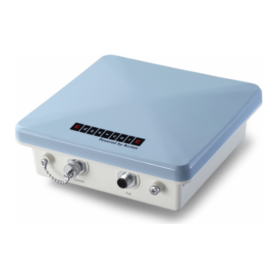
LED Indicators Top View (WA6202AM) N-Type External N-Type External N-Type External N-Type External Antenna Connector Antenna Connector Antenna Connector Antenna Connector (5 GHz) (2.4 GHz) (5 GHz) (2.4 GHz) Right Antenna Right Antenna Left Antenna Left Antenna LED Indicators The access point includes eight status LED indicators, as indicated in the following figure. - Page 24 Introduction The 11a and 11b/g LEDs operate in two display modes, which are configurable through the management interface. The RSSI mode is for aligning antennas in a bridge link. The AP mode is for indicating data traffic rates. The following table describes the wireless status LEDs in AP mode. Status Description No signal detected or the 802.11a radio is disabled.
-
Page 25: Integrated High-Gain Antenna
The WA6202A and WA6202AM units both require an omnidirectional or sector external antenna for 2.4 GHz operation. The following table summarizes the... -
Page 26: Ethernet Port
Introduction Ethernet Port The wireless bridge has one 10BASE-T/100BASE-TX 8-pin DIN port that connects to the power injector module using the included Ethernet cable. The Ethernet port connection provides power to the wireless bridge as well as a data link to the local network. -
Page 27: Grounding Point
Grounding Point The power injector module automatically adjusts to any AC voltage between 100-240 volts at 50 or 60 Hz. No voltage range settings are required. Warning: The power injector module is designed for indoor use only. Never mount the power injector outside with the wireless bridge unit. Grounding Point Even though the wireless bridge includes its own built-in lightning protection, it is important that the unit is properly connected to ground. -
Page 28: System Configuration
AC Power Ground Wire Features and Benefits • WA6202A units support a 5 GHz point-to-point wireless link up 15.4 km (at 6 Mbps data rate) using integrated high-gain 17 dBi antennas • WA6202AM units support 5 GHz point-to-multipoint links using various external antenna options •... -
Page 29: Chapter 2: Network Configuration
Chapter 2: Network Configuration The Dual-band Outdoor Access Point / Bridge system provides access point and bridging services through either the 5 GHz or 2.4 GHz radio interfaces. The wireless bridge units can be used just as normal 802.11a/b/g access points connected to a local wired LAN, providing connectivity and roaming services for wireless clients in an outdoor area. -
Page 30: Infrastructure Wireless Lan
Network Configuration Infrastructure Wireless LAN The access point function of the wireless bridge provides access to a wired LAN for 802.11a/b/g wireless workstations. An integrated wired/wireless LAN is called an Infrastructure configuration. A Basic Service Set (BSS) consists of a group of wireless PC users and an access point that is directly connected to the wired LAN. -
Page 31: Infrastructure Wireless Lan For Roaming Wireless Pcs
Access Point Topologies Infrastructure Wireless LAN for Roaming Wireless PCs The Basic Service Set (BSS) defines the communications domain for each access point and its associated wireless clients. The BSS ID is a 48-bit binary number based on the access point’s wireless MAC address, and is set automatically and transparently as clients associate with the access point. -
Page 32: Bridge Link Topologies
WDS to forward traffic on links between units. Up to 5 WDS links can be specified for a WA6202AM unit, which acts as the “Master” in the wireless bridge network. Other WA6202A units support only one WDS link, which must be to the network’s master unit. -
Page 33: Point-To-Multipoint Configuration
“Slave” units. Using the 5 GHz 8 dBi omnidirectional external antenna, the WA6202AM can connect to WA6202A units up to 3.3 km (2 miles) away. Using the 13.5 dBi 120-degree sector antenna, the WA6202AM can connect to WA6202A units up to 10.3 km (6.4 miles) away. - Page 34 Network Configuration...
-
Page 35: Chapter 3: Bridge Link Planning
Data Rates Using its 5 GHz integrated antenna, the WA6202A Slave bridge can operate over a range of up to 15.4 km (9.6 miles) or provide a high-speed connection of 54 Mbps (108 Mbps in turbo mode). -
Page 36: Antenna Height
Bridge Link Planning Radio Line of Sight Visual Line of Sight If there are obstacles in the radio path, there may still be a radio link but the quality and strength of the signal will be affected. Calculating the maximum clearance from objects on a path is important as it directly affects the decision on antenna placement and height. - Page 37 Radio Path Planning Total Link Distance Max Clearance for Approximate Total Clearance 60% of First Fresnel Clearance Required at Earth Curvature Zone at 5.8 GHz Mid-point of Link 0.25 mile (402 m) 4.5 ft (1.4 m) 4.5 ft (1.4 m) 0.5 mile (805 m) 6.4 ft (1.95 m) 6.4 ft (1.95 m)
-
Page 38: Antenna Position And Orientation
Bridge Link Planning (7.5 ft) mast or pole must be contructed on its roof to achieve the required antenna height. Building B is only three stories high, or 9 m (30 ft), but is located at an elevation that is 12 m (39 ft) higher than bulding A. To mount an anntena at the required height on building B, a mast or pole of only 1.3 m (4.3 ft) is needed. -
Page 39: Radio Interference
Ethernet Cabling Radio Interference The avoidance of radio interference is an important part of wireless link planning. Interference is caused by other radio transmissions using the same or an adjacent channel frequency. You should first scan your proposed site using a spectrum analyzer to determine if there are any strong radio signals using the 802.11a channel frequencies. -
Page 40: Grounding
Bridge Link Planning • Determine if conduits, bracing, or other structures are required for safety or protection of the cable • For lightning protection at the power injector end of the cable, consider using a lightning arrestor immediately before the cable enters the building Grounding It is important that the wireless bridge, cables, and any supporting structures are properly grounded. -
Page 41: Chapter 4: Hardware Installation
Chapter 4: Hardware Installation Before mounting antennas to set up your wireless bridge links, be sure you have selected appropriate locations for each antenna. Follow the guidance and information in Chapter 3: "Bridge Link Planning." Also, before mounting units in their intended locations, you should first perform initial configuration and test the basic operation of the wireless bridge links in a controlled environment over a very short range. - Page 42 Hardware Installation The bridge’s mounting bracket has four parts. One rectangular plate that is used for pole and wall mounting, one square plate that attaches directly to the bridge, and two plates that form an adjustable V-shaped clamp for pole mounting. Mounting on a Pole Perform the following steps to mount the unit to a 1.5 to 2 inch diameter steel pole or tube using the mounting bracket:...
- Page 43 Mount the Unit Attach the adjustable rectangular plate to the bridge with supplied screws Attach the bridge with its mounting plate to the bracket already fixed to the pole. Attach the bridge to the plate on the pole Use the included nuts to secure the wireless bridge to the pole bracket. Note that the wireless bridge tilt angle may need to be adjusted during the antenna alignment process.
-
Page 44: Mounting To A Wall
Hardware Installation Be sure to take account of the antenna polarization direction; all antennas in a link must be mounted with the same polarization. Mounting to a Wall Perform the following steps to mount the unit to a wall using the wall-mounting bracket: Note: The wall-mounting bracket does not allow the wireless bridge’s intrgrated antenna to be aligned. -
Page 45: Connect External Antennas
Typically, a bridge link requires a 5 GHz antenna, and access point operation a 2.4 GHz antenna. WA6202A units also require an external antenna for 2.4 GHz operation. Perform these steps: Mount the external antenna to the same supporting structure as the bridge, within 3 m (10 ft) distance, using the bracket supplied in the antenna package. -
Page 46: Connect Cables To The Unit
Hardware Installation 2.4 GHz N-type Connector 5 GHz External 5 GHz High-gain Panel N-type Connector Antenna 2.4 GHz External Omnidirectional Antenna RF Coaxial Cable Connect Cables to the Unit Warning: Do not connect or disconnect cables or otherwise work with the bridge during periods of lightning activity. -
Page 47: Connect The Power Injector
Connect the Power Injector Console Port PoE (Ethernet) Port Ground Wire Grounding Screw Ethernet Cable Connect the Power Injector To connect the wireless bridge to a power source: Caution: Do not install the power injector outdoors. The unit is for indoor installation only. -
Page 48: Align Antennas
Hardware Installation AC power Ethernet cable from LAN switch Power LED indicator Ethernet cable to wireless bridge Insert the power cable plug directly into the standard AC receptacle on the power injector. Plug the other end of the power cable into a grounded, 3-pin socket, AC power source. - Page 49 Align Antennas The signal strength LEDs indicate the received radio signal strength for a particular bridge link. The more LEDs that turn on, the stronger the signal. Alternatively, you can monitor the Receive Signal Strength Indicator (RSSI) value directly from the management interface.
- Page 50 Hardware Installation Pan the antenna horizontally back and forth while checking the LEDs. If using the pole-mounting bracket with the unit, you must rotate the mounting bracket around the pole. Other external antenna brackets may require a different horizontal adjustment. Find the point where the signal is strongest (all LEDs on) and secure the horizontal adjustment in that position.
-
Page 51: Chapter 5: Initial Configuration
Chapter 5: Initial Configuration The Dual-band Outdoor Access Point / Bridge offers a variety of management options, including a web-based interface, a direct connection to the console port, Telnet, Secure Shell (SSH), or using SNMP software. The initial configuration steps can be made through the web browser interface or CLI. -
Page 52: Initial Configuration Steps
Initial Configuration For a description of how to use the CLI, see “Using the Command Line Interface” on page 7-1. For a list of all the CLI commands and detailed information on using the CLI, refer to “Command Groups” on page 7-6. Initial Configuration Steps Logging In –... -
Page 53: Logging In
Logging In Setting the Country Code – Units sold in the United States are configured by default to use only radio channels 1-11 in 802.11b or 802.11g mode as defined by FCC regulations. Units sold in other countries are configured by default without a country code (i.e., 99). - Page 54 Initial Configuration The home page displays the Main Menu.
-
Page 55: Chapter 6: System Configuration
Chapter 6: System Configuration Before continuing with advanced configuration, first complete the initial configuration steps described in Chapter 5 to set up an IP address for the access point. The access point can be managed by any computer using a web browser (Internet Explorer 5.0 or above, or Netscape 6.2 or above). -
Page 56: Advanced Configuration
System Configuration Advanced Configuration The Advanced Configuration pages include the following options. Table 6-1. Menu Menu Description Page System Configures basic administrative and client access Identification Specifies the host name TCP / IP Settings Configures the IP address, subnet mask, gateway, and domain name servers RADIUS Configures the RADIUS server for wireless client authentication... -
Page 57: System Identification
Advanced Configuration Table 6-1. Menu Menu Description Page Radio Interface G Configures the IEEE 802.11g interface 6-52 Radio Settings Configures common radio signal parameters and other settings for 6-70 each VAP interface Security 6-73 Enables each VAP interface, sets the SSID, and configures wireless security Status Displays information about the access point and wireless clients... - Page 58 System Configuration CLI Commands for System Identification – Enter the global configuration mode, and use the system name command to specify a new system name. Then return to the Exec mode, and use the show system command to display the changes to the system identification settings.
-
Page 59: Tcp / Ip Settings
Advanced Configuration TCP / IP Settings Configuring the access point with an IP address expands your ability to manage the access point. A number of access point features depend on IP addressing to operate. Note: You can use the web browser interface to access IP addressing only if the access point already has an IP address that is reachable through your network. - Page 60 System Configuration • IP Address: The IP address of the access point. Valid IP addresses consist of four decimal numbers, 0 to 255, separated by periods. • Subnet Mask: The mask that identifies the host address bits used for routing to specific subnets.
-
Page 61: Radius
Advanced Configuration RADIUS Remote Authentication Dial-in User Service (RADIUS) is an authentication protocol that uses software running on a central server to control access to RADIUS-aware devices on the network. An authentication server contains a database of user credentials for each user that requires access to the network. A primary RADIUS server must be specified for the access point to implement IEEE 802.1X network access control and Wi-Fi Protected Access (WPA) wireless security. - Page 62 System Configuration...
- Page 63 Advanced Configuration MAC Address Format – MAC addresses can be specified in one of four formats, using no delimeter, with a single dash delimeter, with multiple dash delimeters, and with multiple colon delimeters. VLAN ID Format – A VLAN ID (a number between 1 and 4094) can be assigned to each client after successful authentication using IEEE 802.1X and a central RADIUS server.
- Page 64 System Configuration CLI Commands for RADIUS – From the global configuration mode, use the radius-server address command to specify the address of the primary or secondary RADIUS servers. (The following example configures the settings for the primary RADIUS server.) Configure the other parameters for the RADIUS server. Then use the show radius command from the Exec mode to display the current settings for the primary and secondary RADIUS servers.
-
Page 65: Ssh Settings
Advanced Configuration SSH Settings Telnet is a remote management tool that can be used to configure the access point from anywhere in the network. However, Telnet is not secure from hostile attacks. The Secure Shell (SSH) can act as a secure replacement for Telnet. The SSH protocol uses generated public keys to encrypt all data transfers passing between the access point and SSH-enabled management station clients and ensures that data traveling over the network arrives unaltered. -
Page 66: Authentication
System Configuration CLI Commands for SSH – To enable the SSH server, use the ip ssh-server enable command from the CLI Ethernet interface configuration mode. To set the SSH server UDP port, use the ip ssh-server port command. To view the current settings, use the show system command from the CLI Exec mode (not shown in the following example). - Page 67 Advanced Configuration MAC Authentication – You can configure a list of the MAC addresses for wireless clients that are authorized to access the network. This provides a basic level of authentication for wireless clients attempting to gain access to the network. A database of authorized MAC addresses can be stored locally on the access point or remotely on a central RADIUS server.
- Page 68 System Configuration 802.1X Supplicant – The access point can also operate in a 802.1X supplicant mode. This enables the access point itself to be authenticated with a RADIUS server using a configured MD5 user name and password. This prevents rogue access points from gaining access to the network.
- Page 69 Advanced Configuration CLI Commands for Local MAC Authentication – Use the mac-authentication server command from the global configuration mode to enable local MAC authentication. Use the mac-authentication session-timeout command to set the authentication interval to enable web-based authentication for service billing. Set the default action for MAC addresses not in the local table using the address filter default command, then enter MAC addresses in the local table using the address filter entry command.
- Page 70 System Configuration CLI Commands for RADIUS MAC Authentication – Use the mac-authentication server command from the global configuration mode to enable remote MAC authentication. Set the timeout value for re-authentication using the mac- authentication session-timeout command. Be sure to also configure connection settings for the RADIUS server (not shown in the following example).
-
Page 71: Filter Control
Advanced Configuration Filter Control The access point can employ network traffic frame filtering to control access to network resources and increase security. You can prevent communications between wireless clients and prevent access point management from wireless clients. Also, you can block specific Ethernet traffic from being forwarded by the access point. Inter Client STAs Communication Filter –... - Page 72 System Configuration Uplink Port MAC Address Filtering Status – Prevents traffic with specified source MAC addresses from being forwarded to wireless clients through the access point. You can add a maximum of four MAC addresses to the filter table. (Default: Disabled) •...
-
Page 73: Vlan
Advanced Configuration VLAN The access point can employ VLAN tagging support to control access to network resources and increase security. VLANs separate traffic passing between the access point, associated clients, and the wired network. There can be a VLAN assigned to each associated client, a default VLAN for each VAP (Virtual Access Point) interface, and a management VLAN for the access point. - Page 74 System Configuration When setting up VLAN IDs for each user on the RADIUS server, be sure to use the RADIUS attributes and values as indicated in the following table. Number RADIUS Attribute Value Tunnel-Type VLAN (13) Tunnel-Medium-Type Tunnel-Private-Group-ID VLANID (1 to 4094 as hexadecimal or string) VLAN IDs on the RADIUS server can be entered as hexadecimal digits or a string (see “radius-server vlan-format”...
-
Page 75: Wds Settings
Advanced Configuration WDS Settings Each access point radio interface can be configured to operate in a bridge or repeater mode, which allows it to forward traffic directly to other access point units. To set up bridge links between access point units, you must configure the wireless Distribution System (WDS) forwarding table by specifying the wireless MAC address of all units to which you want to forward traffic. - Page 76 System Configuration • Bridge: Operates as a bridge to other access points. The “Parent” link to the root bridge must be configured. Up to five other ”Child” links are available to other bridges. • Repeater: Operates as a wireless repeater, extending the range for remote wireless clients and connecting them to the root bridge.
- Page 77 Advanced Configuration Spanning Tree Protocol – STP uses a distributed algorithm to select a bridging device (STP-compliant switch, bridge or router) that serves as the root of the spanning tree network. It selects a root port on each bridging device (except for the root device) which incurs the lowest path cost when forwarding a packet from that device to the root device.
- Page 78 System Configuration the root device. All ports connected to designated bridging devices are assigned as designated ports. After determining the lowest cost spanning tree, it enables all root ports and designated ports, and disables all other ports. Network packets are therefore only forwarded between root ports and designated ports, eliminating any possible network loops.
- Page 79 Advanced Configuration • Link Path Cost – This parameter is used by the STP to determine the best path between devices. Therefore, lower values should be assigned to ports attached to faster media, and higher values assigned to ports with slower media. (Path cost takes precedence over port priority.) •...
- Page 80 System Configuration CLI Commands for STP Settings – If the role of a radio interface is set to Repeater, Bridge or Root Bridge, STP can be enabled on the access point to maintain a valid network topology. To globally enable STP, use the bridge stp enable command from the CLI configuration mode.
-
Page 81: Ap Management
Advanced Configuration AP Management The Web, Telnet, and SNMP management interfaces are enabled and open to all IP addresses by default. To provide more security for management access to the access point, specific interfaces can be disabled and management restricted to a single IP address or a limited range of IP addresses. -
Page 82: Administration
System Configuration • Multiple IP: Specifies an address range as defined by the entered IP address and subnet mask. For example, IP address 192.168.1.6 and subnet mask 255.255.255.0, defines all IP addresses from 192.168.1.6 to 192.168.1.254. CLI Commands for AP Management features. Enterprise AP(config)#apmgmtip multiple 192.168.1.6 255.255.255.0 7-21 Enterprise AP(config)#apmgmtui SNMP enable... - Page 83 Advanced Configuration Setting the Timeout Interval You can set the timeout interval for web access to the unit, after which the user will have to re-enter the username and password. Session Timeout for WEB – Sets the time limit for an idle web interface session. (Range: 0-1800 seconds;...
- Page 84 System Configuration Before upgrading new software, verify that the access point is connected to the network and has been configured with a compatible IP address and subnet mask. If you need to download from an FTP or TFTP server, take the following additional steps: •...
- Page 85 Advanced Configuration Firmware Upgrade Local – Downloads an operation code image file from the web management station to the access point using HTTP. Use the Browse button to locate the image file locally on the management station and click Start Upgrade to proceed.
- Page 86 System Configuration Upon uploading a new configuration file you will be prompted to either restore factory settings, or reboot the unit. CLI Commands for Downloading Software from a TFTP Server – Use the copy tftp file command from the Exec mode and then specify the file type, name, and IP address of the TFTP server.
-
Page 87: System Log
Advanced Configuration System Log The access point can be configured to send event and error messages to a System Log Server. The system clock can also be synchronized with a time server, so that all the messages sent to the Syslog server are stamped with the correct time and date. - Page 88 System Configuration Logging Level – Sets the minimum severity level for event logging. (Default: Informational) The system allows you to limit the messages that are logged by specifying a minimum severity level. The following table lists the error message levels from the most severe (Emergency) to least severe (Debug).
-
Page 89: Configuring Sntp
Advanced Configuration CLI Commands for System Logging – To enable logging on the access point, use the logging on command from the global configuration mode. The logging level command sets the minimum level of message to log. Use the logging console command to enable logging to the console. - Page 90 System Configuration Note: The access point also allows you to disable SNTP and set the system clock manually. Set Time Zone – SNTP uses Coordinated Universal Time (or UTC, formerly Greenwich Mean Time, or GMT) based on the time at the Earth’s prime meridian, zero degrees longitude.
-
Page 91: Rssi
Advanced Configuration CLI Commands for the System Clock – The following example shows how to manually set the system time when SNTP server support is disabled on the access point. Enterprise AP(config)#no sntp-server enable 7-34 Enterprise AP(config)#sntp-server date-time 7-35 Enter Year<1970-2100>: 2003 Enter Month<1-12>: 10 Enter Day<1-31>: 10 Enter Hour<0-23>: 18... - Page 92 System Configuration The RSSI controls allow the external connector to be disabled and the receive signal for each WDS port displayed. 6-38...
- Page 93 Advanced Configuration RSSI: • Auto Refresh – Enables or disables the refreshing of RSSI information. • RSSI Value – The displayed RSSI value for a selected port. • Port Number: Selects a specific WDS port for which to display the RSSI output value.
-
Page 94: Snmp
System Configuration SNMP Simple Network Management Protocol (SNMP) is a communication protocol designed specifically for managing devices on a network. Equipment commonly managed with SNMP includes switches, routers and host computers. SNMP is typically used to configure these devices for proper operation in a network environment, as well as to monitor them to evaluate performance or detect potential problems. -
Page 95: Configuring Snmp And Trap Message Parameters
SNMP Configuring SNMP and Trap Message Parameters The access point SNMP agent must be enabled to function (for versions 1, 2c, and 3 clients). Management access using SNMP v1 and v2c also requires community strings to be configured for authentication. Trap notifications can be enabled and sent to up to four management stations. - Page 96 System Configuration Community Name (Read/Write) – Defines the SNMP community access string that has read/write access. Authorized management stations are able to both retrieve and modify MIB objects. (Maximum length: 23 characters, case sensitive; Default: private) Trap Destination (1 to 4) – Enables recipients (up to four) of SNMP notifications. •...
- Page 97 SNMP Trap Configuration – Allows selection of specific SNMP notifications to send. The following items are available: • sysSystemUp - The access point is up and running. • sysSystemDown - The access point is about to shutdown and reboot. • sysRadiusServerChanged - The access point has changed from the primary RADIUS server to the secondary, or from the secondary to the primary.
- Page 98 System Configuration • dot11StationDisassociate - A client station no longer associates with the network. • dot11StationAuthenticateFail - A client station has tried and failed to authenticate to the network. • Enable All Traps - Click the button to enable all the available traps. •...
- Page 99 SNMP To view the current SNMP settings, use the show snmp command. Enterprise AP#show snmp 7-54 SNMP Information ============================================== Service State : Enable Community (ro) : ***** Community (rw) : ***** Location : WC-19 Contact : Paul EngineId :80:00:07:e5:80:00:00:2e:62:00:00:00:18 EngineBoots:1 Trap Destinations: 192.168.1.9, Community: *****, State: Enabled 0.0.0.0, Community: *****, State: Disabled...
-
Page 100: Configuring Snmpv3 Users
System Configuration Configuring SNMPv3 Users The access point allows up to 10 SNMP v3 users to be configured. Each user must be defined by a unique name, assigned to one of three pre-defined security groups, and configured with specific authentication and encryption settings. User –... - Page 101 SNMP CLI Commands for Configuring SNMPv3 Users – Use the snmp-server engine-id command to define the SNMP v3 engine before assigning users to groups. Use the snmp-server user command to assign users to one of the three groups and set the appropriate authentication and encryption types to be used.
-
Page 102: Configuring Snmpv3 Trap Filters
System Configuration Configuring SNMPv3 Trap Filters SNMP v3 users can be configured to receive notification messages from the access point. An SNMP Target ID is created that specifies the SNMP v3 user, IP address, and UDP port. A user-defined notification filter can be created so that specific notifications can be prevented from being sent to particular targets. - Page 103 SNMP To add more subtree IDs to the filter, return to the SNMP Trap Filters page and click the Edit button. In the Edit page, click the New button to access the Add SNMP Notification Subtree page and configure a new subtree ID to be filtered. Note: Only the New Filter page allows the Filter ID to be configured.
-
Page 104: Configuring Snmpv3 Targets
System Configuration CLI Commands for Configuring SNMPv3 Trap Filters – To create a notification filter, use the snmp-server filter command from the CLI configuration mode. Use the command more than once with the same filter ID to build a filter that includes or excludes multiple MIB objects. - Page 105 SNMP When you click on the New or Edit button in the SNMP Targets page, a new page opens where the target parameters are configured. Define the parameters and select a filter, if required. Note that the SNMP v3 user name must first be defined (See “Configuring SNMPv3 Users”...
-
Page 106: Radio Interface
System Configuration Enterprise AP(config)#snmp-server targets mytraps 192.168.1.33 chris 7-48 Enterprise AP(config)#snmp-server filter-assignment mytraps trapfilter 7-50 Enterprise AP(config)#exit Enterprise AP#show snmp target 7-52 Host ID : mytraps User : chris IP Address : 192.168.1.33 UDP Port : 162 ============================= Enterprise AP#show snmp filter-assignments 7-53 HostID FilterID... -
Page 107: Radio Settings A (802.11A)
Radio Interface Radio Settings A (802.11a) The IEEE 802.11a interface operates within the 5 GHz band, at up to 54 Mbps in normal mode or up to 108 Mbps in Turbo mode. First configure the radio settings that apply to the individual VAPs (Virtual Access Point) and the common radio settings that apply to the overall system. - Page 108 System Configuration Configuring VAP Radio Settings To configure VAP radio settings, select the Radio Settings page. 6-54...
- Page 109 Radio Interface Default VLAN ID – The VLAN ID assigned to wireless clients associated to the VAP interface that are not assigned to a specific VLAN by RADIUS server configuration. (Default: 1) Closed System – When enabled, the VAP interface does not include its SSID in beacon messages.
-
Page 110: Configuring Rogue Ap Detection
System Configuration CLI Commands for the Configuring the VAPs – From the global configuration mode, enter the interface wireless a command to access the 802.11a radio interface. From the 802.11a interface mode, you can access radio settings that apply to all VAP interfaces. - Page 111 Radio Interface The access point can be configured to periodically scan all radio channels and find other access points within range. A database of nearby access points is maintained where any rogue APs can be identified. During a scan, Syslog messages (see “Enabling System Logging”...
- Page 112 System Configuration using the rogue-ap scan command. To view the database of detected access points, use the show rogue-ap command from the Exec level. 7-88 Enterprise AP(config)#interface wireless g Enter Wireless configuration commands, one per line. 7-114 Enterprise AP(if-wireless g)#rogue-ap enable configure either syslog or trap or both to receive the rogue APs detected.
- Page 113 Radio Interface Configuring Common Radio Settings To configure common radio settings, select the Radio Settings page, and scroll down to below the VAP radio settings. Turbo Mode – The normal 802.11a/b/g wireless operation mode provides connections up to 54 Mbps. Turbo Mode is an enhanced mode (not regulated in IEEE 802.11a) that provides a higher data rate of up to 108 Mbps.
- Page 114 System Configuration Radio Channel – The radio channel that the access point uses Normal Mode to communicate with wireless clients. When multiple access points are deployed in the same area, set the channel on neighboring access points at least four channels apart to avoid interference with each other.
- Page 115 • Left: The radio uses a single antenna on the left side. Select this method when using an optional external antenna that is connected to the left antenna connector. Also select this method when using the integrated 5 GHz antenna. Top View (WA6202A) N-Type External N-Type External N-Type External...
- Page 116 System Configuration Antenna Location – Selects the mounting location of the antenna in use; either “Indoor” or “Outdoor.” Selecting the correct location ensures that the access point only uses radio channels that are permitted in the country of operation. (Default: Indoor) MIC Mode –...
- Page 117 Radio Interface try setting the fragment size to send smaller fragments. This will speed up the retransmission of smaller frames. However, it is more efficient to set the fragment size larger if very little or no interference is present because it requires overhead to send multiple frames.
- Page 118 System Configuration CLI Commands for the Common Radio Settings – From the global configuration mode, enter the interface wireless a command to access the 802.11a radio interface. From the 802.11a interface mode, you can access radio settings that apply to all VAP interfaces.
- Page 119 Radio Interface types of traffic, WMM allows the priority levels to be configured to match any network-wide QoS policy. WMM also specifies a protocol that access points can use to communicate the configured traffic priority levels to QoS-enabled wireless clients. Table 6-1.
- Page 120 System Configuration CWMin CWMax iority AIFS Random Backoff Minimum Wait Time Random Wait Time CWMin iority Random Backoff AIFS Minimum Wait Time Random Wait Time Figure 6-1. WMM Backoff Wait Times For high-priority traffic, the AIFSN and CW values are smaller. The smaller values equate to less backoff and wait time, and therefore more transmit opportunities.
- Page 121 Radio Interface WMM – Sets the WMM operational mode on the access point. When enabled, the parameters for each AC queue will be employed on the access point and QoS capabilities are advertised to WMM-enabled clients. (Default: Support) • Disable: WMM is disabled. •...
- Page 122 System Configuration CLI Commands for WMM – Enter interface wireless mode and type wmm required for clients that want to associate with the access point. The wmm-acknowledge-policy command is used to enable or disable a policy for each access category. The wmmparms command defines detailed WMM parameters. Enterprise AP(if-wireless a)#wmm required 7-136 Enterprise AP(if-wireless a)#wmm-acknowledge-policy 0 noack...
- Page 123 Radio Interface To view the current 802.11a radio settings for the VAP interface, use the show interface wireless a [0-3] command. 7-111 Enterprise AP#show interface wireless a 0 Wireless Interface Information ============================================================= --------------------Identification--------------------------- Description : Enterprise 802.11a Access Point SSID : VAP_TEST_11A 0 Turbo Mode : DISABLED...
-
Page 124: Radio Settings G (802.11G)
System Configuration ----------------Quality of Service--------------------------- WMM Mode : SUPPORTED WMM Acknowledge Policy AC0(Best Effort) : Ack AC1(Background) : Acknowledge AC2(Video) : Acknowledge AC3(Voice) : Acknowledge WMM BSS Parameters AC0(Best Effort) : logCwMin: logCwMax: 10 AIFSN: Admission Control: No TXOP Limit: 0.000 ms AC1(Background) : logCwMin: logCwMax: 10... - Page 125 Radio Interface Most of the 802.11g commands are identical to those used by the 802.11a interface. For information on the these commands, refer to the following sections: • “Configuring VAP Radio Settings” on page 6-54 • “Configuring Rogue AP Detection” on page 6-56 •...
- Page 126 System Configuration Radio Channel – The radio channel that the access point uses to communicate with wireless clients. When multiple access points are deployed in the same area, set the channel on neighboring access points at least five channels apart to avoid interference with each other.
-
Page 127: Security
Radio Interface CLI Commands for the 802.11g Wireless Interface – From the global configuration mode, enter the interface wireless g command to access the 802.11g radio interface. The 802.11g radio can be forced to an 802.11g-only, 802.11b-only, or mixed 802.11b/g operating mode using the radio-mode command. You should set the desired operating mode before configuring channel settings (the default is mixed 802.11b/g operation). - Page 128 System Configuration A summary of wireless security considerations is listed in the following table. Table 6-2. Wireless Security Considerations Security Client Support Implementation Considerations Mechanism • Provides only weak security Built-in support on all 802.11a and 802.11g devices • Requires manual key management WEP over 802.1X Requires 802.1X client support •...
- Page 129 Radio Interface The access point can simultaneously support clients using various different security mechanisms. The configuration for these security combinations are outlined in the following table. Note that MAC address authentication can be configured independently to work with all security mechanisms and is indicated separately in the table.
- Page 130 System Configuration Table 6-3. Security Combinations Client Security RADIUS Configuration Summary Combination Server Authentication Dynamic WEP and Interface Detail Settings: Local or Disabled Yes 802.1x WPA Authentication: WPA Encryption: Enable WPA Configuration: Supported Cipher Suite: WEP 802.1x: Required Set 802.1x key refresh and reauthentication rates Static and dynamic Enter 1 to 4 WEP keys Local or Disabled Yes...
- Page 131 Radio Interface a. The configuration summary does not include the set up for MAC authentication (see page 4-15) or RADIUS server (see page 2-9). b. The configuration of RADIUS MAC authentication together with 802.1x WPA or WPA Pre-shared Key is not supported. c.
- Page 132 System Configuration Enable – Enables radio communications on the VAP interface. (Default: Disabled) Note: You must first enable VAP interface 0 before you can enable other VAP interfaces. SSID – The name of the basic service set provided by a VAP interface. Clients that want to connect to the network through the access point must set their SSID to the same as that of an access point VAP interface.
- Page 133 Radio Interface • Alphanumeric: Enter keys as 5 alphanumeric characters for 64 bit keys, 13 alphanumeric characters for 128 bit keys, or 16 alphanumeric characters for 152 bit keys (802.11a radio only). Key Number – Selects the key number to use for encryption for each VAP interface. If the clients have all four keys configured to the same values, you can change the encryption key to any of the four settings without having to update the client keys.
- Page 134 System Configuration Note: To use 802.1X on wireless clients requires a network card driver and 802.1X client software that supports the EAP authentication type that you want to use. Windows 2000 SP3 or later and Windows XP provide 802.1X client support. Windows XP also provides native WPA support.
- Page 135 Radio Interface 7-88 Enterprise AP(config)#interface wireless g Enter Wireless configuration commands, one per line. 7-122 Enterprise AP(if-wireless g)#key 1 128 ascii abcdeabcdeabc 7-95 Enterprise AP(if-wireless g)#vap 0 7-122 Enterprise AP(if-wireless g: VAP[0])#auth shared-key Data Encryption is set to enabled. Remember to set the share key using "key" command. 7-123 Enterprise AP(if-wireless g: VAP[0])#transmit-key 1 Enterprise AP(if-wireless g: VAP[0])#exit...
- Page 136 System Configuration ----------------Antenna------------------------------------------------- Antenna Control method : Diversity Antenna ID : 0x0000(Default Antenna) Antenna Location : Indoor ----------------Quality of Service--------------------------------------- WMM Mode : SUPPORTED WMM Acknowledge Policy AC0(Best Effort) : Acknowledge AC1(Background) : Acknowledge AC2(Video) : Acknowledge AC3(Voice) : Acknowledge WMM BSS Parameters AC0(Best Effort) : logCwMin:...
- Page 137 Radio Interface to enable data encryption. To view the current security settings, use the show interface wireless a [0-3] or show interface wireless g [0-3] command (not shown in example). Enterprise AP(if-wireless g)#vap 0 Enterprise AP(if-wireless g: VAP[0])#802.1X required 7-65 Enterprise AP(if-wireless g: VAP[0])#802.1X 7-66 broadcast-key-refresh-rate 5...
- Page 138 System Configuration the access point and all wireless clients. The PSK mode uses the same TKIP packet encryption and key management as WPA in the enterprise, providing a robust and manageable alternative for small networks. Mixed WPA and WEP Client Support: WPA enables the access point to indicate its supported encryption and authentication mechanisms to clients using its beacon signal.
- Page 139 Radio Interface information form a Security Association that the access point names and holds in a cache. • Preauthentication: Each time a client roams to another access point it has to be fully re-authenticated. This authentication process is time consuming and can disrupt applications running over the network.
- Page 140 System Configuration The WPA configuration parameters are described below: Encryption – You must enable data encryption in order to enable all types of encryption (WEP, TKIP, or AES) in the access point. Pre-Authentication – When using WPA2 over 802.1X, pre-authentication can be enabled, which allows clients to roam to a new access point and be quickly associated without performing full 802.1X authentication.
- Page 141 Radio Interface The configuration settings for WPA are summarized below: Table 6-4. WPA Configuration Settings WPA and WPA2 pre-shared key only WPA and WPA2 over 802.1X Encryption: Enabled Encryption: Enabled Authentication Setup: WPA-PSK, WPA2-PSK, or Authentication Setup: WPA, WPA2, WPA-WPA2-mixed WPA-WPA2-mixed Cipher Suite: WEP/TKIP/AES-CCMP Cipher Suite: WEP/TKIP/AES-CCMP...
- Page 142 System Configuration CLI Commands for WPA Over 802.1X Security – From the VAP interface configuration mode, use the auth wpa required command to select WPA over 802.1X security. Then set the 802.1X key refresh rates. To view the current security settings, use the show interface wireless a [0-3] or show interface wireless g [0-3] command (not shown in example).
- Page 143 Radio Interface Open the Security page, and click More for one of the VAP interfaces. You can enable 802.1X as optionally supported or as required to enhance the security of the wireless network. (Default: Disable) • Disable: The access point does not support 802.1X authentication for any wireless client.
-
Page 144: Status Information
System Configuration CLI Commands for 802.1X Authentication – Use the 802.1X supported command from the VAP interface mode to enable 802.1X authentication. Set the session and broadcast key refresh rate, and the re-authentication timeout. To display the current settings, use the show interface wireless command from the Exec mode (not shown in the example). - Page 145 Status Information AP System Configuration – The AP System Configuration table displays the basic system configuration settings: • System Up Time: Length of time the management agent has been up. • Ethernet MAC: The physical layer address for the Ethernet port. •...
- Page 146 System Configuration • Bootrom Version: Show the bootrom version number. • Hardware Version: Shows the hardware version number. AP Wireless Configuration – The AP Wireless Configuration tables display the radio and VAP interface settings listed below. Note that Interface Wireless A refers to the 802.11a radio and Interface Wireless G refers the 802.11b/g radio.
-
Page 147: Station Status
Status Information Station Status The Station Status window shows the wireless clients currently associated with the access point. The Station Configuration page displays basic connection information for all associated stations as described below. Note that this page is automatically refreshed every five seconds. •... - Page 148 System Configuration • Static – The client is using static WEP keys for encryption. CLI Commands for Displaying Station Status – To view status of clients currently associated with the access point, use the show station command from the Exec mode.
-
Page 149: Event Logs
Status Information Event Logs The Event Logs window shows the log messages generated by the access point and stored in memory. The Event Logs table displays the following information: • Log Time: The time the log message was generated. • Event Level: The logging level associated with this message. For a description of the various levels, see “logging level”... - Page 150 System Configuration CLI Commands for Displaying the Logging Status – From the global configuration mode, use the show logging command. Enterprise AP#show loggging 7-32 Logging Information ============================================ Syslog State : Enabled Logging Console State : Enabled Logging Level : Alert Logging Facility Type : 16 Servers...
-
Page 151: Stp Status
Status Information STP Status The STP Status window shows the STP status for each port. • ID: Displays the port ID number. • Priority: The priority designated to the specified port. • Path Cost: Displays the path cost value for the specified port. •... - Page 152 System Configuration 6-98...
-
Page 153: Chapter 7: Command Line Interface
Chapter 7: Command Line Interface Using the Command Line Interface Accessing the CLI When accessing the management interface for the over a direct connection to the console port, or via a Telnet connection, the access point can be managed by entering command keywords and parameters at the prompt. -
Page 154: Entering Commands
Command Line Interface If your corporate network is connected to another network outside your office or to the Internet, you need to apply for a registered IP address. However, if you are attached to an isolated network, then you can use any IP address that matches the network segment to which you are attached. -
Page 155: Command Completion
Entering Commands Command Completion If you terminate input with a Tab key, the CLI will print the remaining characters of a partial keyword up to the point of ambiguity. I the “configure” example, typing con followed by a tab will result in printing the command up to “configure.” Getting Help on Commands You can display a brief description of the help system by entering the help command. -
Page 156: Partial Keyword Lookup
Command Line Interface Partial Keyword Lookup If you terminate a partial keyword with a question mark, alternatives that match the initial letters are provided. (Remember not to leave a space between the command and question mark.) For example “s?” shows all the keywords starting with “s.” Enterprise AP#show s? snmp sntp... -
Page 157: Exec Commands
Entering Commands Exec Commands When you open a new console session on an access point, the system enters Exec command mode. Only a limited number of the commands are available in this mode. You can access all other commands only from the configuration mode. To access Exec mode, open a new console session with the user name “admin.”... -
Page 158: Command Line Processing
Command Line Interface Command Line Processing Commands are not case sensitive. You can abbreviate commands and parameters as long as they contain enough letters to differentiate them from any other currently available commands or parameters. You can use the Tab key to complete partial commands, or enter a partial command followed by the “?”... -
Page 159: General Commands
General Commands Table 7-2. Command Groups Command Group Description Page SNMP Configures community access strings and trap managers 7-40 Flash/File Manages code image or access point configuration files 7-55 RADIUS Configures the RADIUS client used with 802.1X authentication 7-58 802.1X Authentication Configures 802.1X authentication 7-65 MAC Address Configures MAC address authentication... -
Page 160: Configure
Command Line Interface configure This command activates Global Configuration mode. You must enter this mode to modify most of the settings on the access point. You must also enter Global Configuration mode prior to enabling the context modes for Interface Configuration. See “Using the Command Line Interface”... -
Page 161: Ping
General Commands Example This example shows how to return to the Exec mode from the Interface Configuration mode, and then quit the CLI session: Enterprise AP(if-ethernet)#exit Enterprise AP#exit CLI session with the Access Point is now closed Username: ping This command sends ICMP echo request packets to another node on the network. Syntax ping <host_name | ip_address>... -
Page 162: Reset
Command Line Interface reset This command restarts the system or restores the factory default settings. Syntax reset <board | configuration> • board - Reboots the system. • configuration - Resets the configuration settings to the factory defaults, and then reboots the system. Default Setting None Command Mode... -
Page 163: Show Line
System Management Commands show line This command displays the console port’s configuration settings. Command Mode Exec Example The console port settings are fixed at the values shown below. Enterprise AP#show line Console Line Information ====================================================== databits parity : none speed : 9600 stop bits ======================================================... -
Page 164: Country
Command Line Interface Table 7-4. System Management Commands Command Function Mode Page Web Server ip http port Specifies the port to be used by the web browser interface 7-17 ip http server Allows the access point to be monitored or configured from a 7-18 browser ip http session-timeout Sets the timeout for the web browser interface... - Page 165 System Management Commands Table 7-5. Country Codes Country Code Country Code Country Code Country Code Belgium Guatemala Mexico Taiwan Honduras Monaco Thailand Belize Hong Kong Morocco Trinidad & Tobago Bolivia Hungary Netherlands Tunisia Brazil Iceland New Zealand Turkey Brunei India Norway Ukraine Darussalam...
-
Page 166: Prompt
Command Line Interface • The available Country Code settings can be displayed by using the country ? command. Example Enterprise AP#country tw Enterprise AP# prompt This command customizes the CLI prompt. Use the no form to restore the default prompt. Syntax prompt <string>... -
Page 167: Username
System Management Commands Command Mode Global Configuration Example Enterprise AP(config)#system name AP Enterprise AP(config)# username This command configures the user name for management access. Syntax username <name> name - The name of the user. (Length: 3-16 characters, case sensitive) Default Setting admin Command Mode Global Configuration... -
Page 168: Ip Ssh-Server Enable
Command Line Interface ip ssh-server enable This command enables the Secure Shell server. Use the no form to disable the server. Syntax ip ssh-server enable no ip ssh-server Default Setting Interface enabled Command Mode Interface Configuration (Ethernet) Command Usage • The access point supports Secure Shell version 2.0 only. •... -
Page 169: Ip Telnet-Server Enable
System Management Commands ip telnet-server enable This command enables the Telnet server. Use the no form to disable the server. Syntax ip telnet-server enable no ip telnet-server Default Setting Interface enabled Command Mode Interface Configuration (Ethernet) Example Enterprise AP(if-ethernet)#ip telnet-server enable Enterprise AP(if-ethernet)# ip http port This command specifies the TCP port number used by the web browser interface. -
Page 170: Ip Http Server
Command Line Interface ip http server This command allows this device to be monitored or configured from a browser. Use the no form to disable this function. Syntax ip http server no ip http server Default Setting Enabled Command Mode Global Configuration Example Enterprise AP(config)#ip http server... -
Page 171: Ip Https Port
System Management Commands ip https port Use this command to specify the UDP port number used for HTTPS/SSL connection to the access point’s Web interface. Use the no form to restore the default port. Syntax ip https port <port_number> no ip https port port_number –... - Page 172 Command Line Interface Syntax ip https server no ip https server Default Setting Enabled Command Mode Global Configuration Command Usage • Both HTTP and HTTPS service can be enabled independently. • If you enable HTTPS, you must indicate this in the URL: https://device:port_number] •...
-
Page 173: Apmgmtip
System Management Commands APmgmtIP This command specifies the client IP addresses that are allowed management access to the access point through various protocols. Caution: Secure Web (HTTPS) connections are not affected by the UI Management or IP Management settings. Syntax APmgmtIP <multiple IP_address subnet_mask | single IP_address | any>... -
Page 174: Apmgmtui
Command Line Interface APmgmtUI This command enables and disables management access to the access point through SNMP, Telnet and web interfaces. Caution: Secure Web (HTTPS) connections are not affected by the UI Management or IP Management settings. Syntax APmgmtUI <[SNMP | Telnet | Web] enable | disable> •... -
Page 175: Show System
System Management Commands show system This command displays basic system configuration settings. Default Setting None Command Mode Exec Example Enterprise AP#show system System Information ========================================================== Serial Number : A123456789 System Up time : 0 days, 4 hours, 33 minutes, 29 seconds System Name : Enterprise Wireless AP System Location... -
Page 176: Show Version
Command Line Interface show version This command displays the software version for the system. Command Mode Exec Example Enterprise AP#show version Version Information ========================================= Version: v4.3.2.2 Date : Dec 20 2005, 18:38:12 ========================================= Enterprise AP# show config This command displays detailed configuration information for the system. Command Mode Exec Example... - Page 177 System Management Commands Hardware Version Information =========================================== Hardware version R01A =========================================== Ethernet Interface Information ======================================== IP Address : 192.168.0.151 Subnet Mask : 255.255.255.0 Default Gateway : 192.168.0.1 Primary DNS : 210.200.211.225 Secondary DNS : 210.200.211.193 Speed-duplex : 100Base-TX Full Duplex Admin status : Up Operational status...
- Page 178 Command Line Interface Logging Information ===================================================== Syslog State : Disabled Logging Console State : Disabled Logging Level : Informational Logging Facility Type : 16 Servers 1: 0.0.0.0 , UDP Port: 514, State: Disabled 2: 0.0.0.0 , UDP Port: 514, State: Disabled 3: 0.0.0.0 , UDP Port: 514, State: Disabled...
- Page 179 System Management Commands dot11InterfaceAGFail Enabled dot11InterfaceBFail Enabled dot11StationAssociation Enabled dot11StationAuthentication Enabled dot11StationReAssociation Enabled dot11StationRequestFail Enabled dot1xAuthFail Enabled dot1xAuthNotInitiated Enabled dot1xAuthSuccess Enabled dot1xMacAddrAuthFail Enabled dot1xMacAddrAuthSuccess Enabled iappContextDataSent Enabled iappStationRoamedFrom Enabled iappStationRoamedTo Enabled localMacAddrAuthFail Enabled localMacAddrAuthSuccess Enabled pppLogonFail Enabled sntpServerFail Enabled configFileVersionChanged Enabled radiusServerChanged Enabled...
-
Page 180: Show Hardware
Command Line Interface SSH Server : ENABLED SSH Server Port : 22 Telnet Server : ENABLED WEB Redirect : DISABLED DHCP Relay : DISABLED ============================================================== Version Information ========================================= Version: v4.3.2.2 Date : Dec 20 2005, 18:38:12 ========================================= Enterprise AP# show hardware This command displays the hardware version of the system. -
Page 181: Logging On
System Logging Commands logging on This command controls logging of error messages; i.e., sending debug or error messages to memory. The no form disables the logging process. Syntax [no] logging on Default Setting Disabled Command Mode Global Configuration Command Usage The logging process controls error messages saved to memory. -
Page 182: Logging Console
Command Line Interface Example Enterprise AP(config)#logging host 1 10.1.0.3 Enterprise AP(config)# logging console This command initiates logging of error messages to the console. Use the no form to disable logging to the console. Syntax logging console no logging console Default Setting Disabled Command Mode... -
Page 183: Logging Facility-Type
System Logging Commands Command Usage Messages sent include the selected level down to Emergency level. Level Argument Description Emergency System unusable Alert Immediate action needed Critical Critical conditions (e.g., memory allocation, or free memory error - resource exhausted) Error Error conditions (e.g., invalid input, default used) Warning Warning conditions (e.g., return false, unexpected return) Notice... -
Page 184: Logging Clear
Command Line Interface Command Usage The command specifies the facility type tag sent in syslog messages. (See RFC 3164.) This type has no effect on the kind of messages reported by the access point. However, it may be used by the syslog server to sort messages or to store messages in the corresponding database. -
Page 185: Show Event-Log
System Clock Commands show event-log This command displays log messages stored in the access point’s memory. Syntax show event-log Command Mode Exec Example Enterprise AP#show event-log Mar 09 11:57:55 Information: 802.11g:11g Radio Interface Enabled Mar 09 11:57:55 Information: 802.11g:Radio channel updated to 8 Mar 09 11:57:34 Information: 802.11g:11g Radio Interface Enabled Mar 09 11:57:18... -
Page 186: Sntp-Server Ip
Command Line Interface sntp-server ip This command sets the IP address of the servers to which SNTP time requests are issued. Use the this command with no arguments to clear all time servers from the current list. Syntax sntp-server ip <1 | 2> <ip> •... -
Page 187: Sntp-Server Date-Time
System Clock Commands Command Mode Global Configuration Command Usage The time acquired from time servers is used to record accurate dates and times for log events. Without SNTP, the access point only records the time starting from the factory default set at the last bootup (i.e., 00:14:00, January 1, 1970). -
Page 188: Sntp-Server Daylight-Saving
Command Line Interface sntp-server daylight-saving This command sets the start and end dates for daylight savings time. Use the no form to disable daylight savings time. Syntax sntp-server daylight-saving no sntp-server daylight-saving Default Setting Disabled Command Mode Global Configuration Command Usage The command sets the system clock back one hour during the specified period. -
Page 189: Show Sntp
System Clock Commands Command Usage This command sets the local time zone relative to the Coordinated Universal Time (UTC, formerly Greenwich Mean Time or GMT), based on the earth’s prime meridian, zero degrees longitude. To display a time corresponding to your local time, you must indicate the number of hours and minutes your time zone is east (before) or west (after) of UTC. -
Page 190: Dhcp Relay Commands
Command Line Interface DHCP Relay Commands Dynamic Host Configuration Protocol (DHCP) can dynamically allocate an IP address and other configuration information to network clients that broadcast a request. To receive the broadcast request, the DHCP server would normally have to be on the same subnet as the client. -
Page 191: Dhcp-Relay
DHCP Relay Commands dhcp-relay This command configures the primary and secondary DHCP server addresses. Syntax dhcp-relay <primary | secondary> <ip_address> • primary - The primary DHCP server. • secondary - The secondary DHCP server. • ip_address - IP address of the server. Default Setting Primary and secondary: 0.0.0.0 Command Mode... -
Page 192: Snmp Commands
Command Line Interface SNMP Commands Controls access to this access point from management stations using the Simple Network Management Protocol (SNMP), as well as the hosts that will receive trap messages. Table 7-9. SNMP Commands Command Function Mode Page snmp-server community 7-41 Sets up the community access string to permit access to SNMP commands... -
Page 193: Snmp-Server Community
SNMP Commands snmp-server community This command defines the community access string for the Simple Network Management Protocol. Use the no form to remove the specified community string. Syntax snmp-server community string [ro | rw] no snmp-server community string • string - Community string that acts like a password and permits access to the SNMP protocol. -
Page 194: Snmp-Server Location
Command Line Interface Command Mode Global Configuration Example Enterprise AP(config)#snmp-server contact Paul Enterprise AP(config)# Related Commands snmp-server location (7-42) snmp-server location This command sets the system location string. Use the no form to remove the location string. Syntax snmp-server location <text> no snmp-server location text - String that describes the system location. -
Page 195: Snmp-Server Host
SNMP Commands Command Mode Global Configuration Command Usage • This command enables both authentication failure notifications and link-up-down notifications. • The snmp-server host command specifies the host device that will receive SNMP notifications. Example Enterprise AP(config)#snmp-server enable server Enterprise AP(config)# Related Commands snmp-server host (7-43) snmp-server host... -
Page 196: Snmp-Server Trap
Command Line Interface Command Usage The snmp-server host command is used in conjunction with the snmp-server enable server command to enable SNMP notifications. Example Enterprise AP(config)#snmp-server host 1 10.1.19.23 batman Enterprise AP(config)# Related Commands snmp-server enable server (7-42) snmp-server trap This command enables the access point to send specific SNMP traps (i.e., notifications). -
Page 197: Snmp-Server Engine-Id
SNMP Commands - iappStationRoamedTo - A client station has roamed to another access point (identified by its IP address). - localMacAddrAuthFail - A client station has failed authentication with the local MAC address database on the access point. - localMacAddrAuthSuccess - A client station has successfully authenticated its MAC address with the local database on the access point. -
Page 198: Snmp-Server User
Command Line Interface Command Mode Global Configuration Command Usage • This command is used in conjunction with the snmp-server user command. • Entering this command invalidates all engine IDs that have been previously configured. • If the engineID is deleted or changed, all SNMP users will be cleared. You will need to reconfigure all existing users Example Enterprise AP(config)#snmp-server engine-id 1a:2b:3c:4d:00:ff... - Page 199 SNMP Commands - RWAuth - A read/write group using authentication, but no data encryption. Users in this group send SNMP messages that use an MD5 key/password for authentication, but not a DES key/password for encryption. - RWPriv - A read/write group using authentication and data encryption. Users in this group send SNMP messages that use an MD5 key/ password for authentication and a DES key/password for encryption.
-
Page 200: Snmp-Server Targets
Command Line Interface snmp-server targets This command configures SNMP v3 notification targets. Use the no form to delete an SNMP v3 target. Syntax snmp-server targets <target-id> <ip-addr> <sec-name> [version {3}] [udp-port {port-number}] [notification-type {TRAP}] no snmp-server targets <target-id> • target-id - A user-defined name that identifies a receiver of SNMP notifications. -
Page 201: Snmp-Server Filter
SNMP Commands snmp-server filter This command configures SNMP v3 notification filters. Use the no form to delete an SNMP v3 filter or remove a subtree from a filter. Syntax snmp-server filter <filter-id> <include | exclude> <subtree> [mask {mask}] no snmp-server filter <filter-id> [subtree] •... -
Page 202: Snmp-Server Filter-Assignments
Command Line Interface snmp-server filter-assignments This command assigns SNMP v3 notification filters to targets. Use the no form to remove an SNMP v3 filter assignment. Syntax snmp-server filter-assignments <target-id> <filter-id> no snmp-server filter-assignments <target-id> • target-id - A user-defined name that identifies a receiver of SNMP notifications. -
Page 203: Show Snmp Users
SNMP Commands Example Enterprise AP#show snmp groups GroupName SecurityModel :USM SecurityLevel :NoAuthNoPriv GroupName :RWAuth SecurityModel :USM SecurityLevel :AuthNoPriv GroupName :RWPriv SecurityModel :USM SecurityLevel :AuthPriv Enterprise AP# show snmp users This command displays the SNMP v3 users and settings. Syntax show snmp users Command Mode Exec Example... -
Page 204: Show Snmp Target
Command Line Interface Example Enterprise AP#show snmp group-assignments GroupName :RWPriv UserName :chris Enterprise AP# Enterprise AP# show snmp target This command displays the SNMP v3 notification target settings. Syntax show snmp target Command Mode Exec Example Enterprise AP#show snmp target Host ID : mytraps User... -
Page 205: Show Snmp Filter-Assignments
SNMP Commands show snmp filter-assignments This command displays the SNMP v3 notification filter assignments. Syntax show snmp filter-assignments Command Mode Exec Example Enterprise AP#show snmp filter-assignments HostID FilterID mytraps trapfilter Enterprise AP# 7-53... -
Page 206: Show Snmp
Command Line Interface show snmp This command displays the SNMP configuration settings. Command Mode Exec Example Enterprise AP#show snmp SNMP Information ============================================== Service State : Enable Community (ro) : ***** Community (rw) : ***** Location : WC-19 Contact : Paul EngineId :80:00:07:e5:80:00:00:2e:62:00:00:00:18 EngineBoots:1... -
Page 207: Flash/File Commands
Flash/File Commands Flash/File Commands These commands are used to manage the system code or configuration files. Table 7-10. Flash/File Commands Command Function Mode Page bootfile Specifies the file or image used to start up the system 7-55 copy Exec 7-56 Copies a code image or configuration between flash memory and a FTP/TFTP server delete... -
Page 208: Copy
Command Line Interface copy This command copies a boot file, code image, or configuration file between the access point’s flash memory and a FTP/TFTP server. When you save the configuration settings to a file on a FTP/TFTP server, that file can later be downloaded to the access point to restore system operation. -
Page 209: Delete
Flash/File Commands The following example shows how to download a configuration file: Enterprise AP#copy tftp file 1. Application image 2. Config file 3. Boot block image Select the type of download<1,2,3>: [1]:2 TFTP Source file name:syscfg TFTP Server IP:192.168.1.19 Enterprise AP# delete This command deletes a file or image. -
Page 210: Dir
Command Line Interface This command displays a list of files in flash memory. Command Mode Exec Command Usage File information is shown below: Column Heading Description File Name The name of the file. Type (2) Operation Code and (5) Configuration file File Size The length of the file in bytes. -
Page 211: Radius Client
RADIUS Client RADIUS Client Remote Authentication Dial-in User Service (RADIUS) is a logon authentication protocol that uses software running on a central server to control access for RADIUS-aware devices to the network. An authentication server contains a database of credentials, such as users names and passwords, for each wireless client that requires access to the access point. -
Page 212: Radius-Server Port
Command Line Interface Command Mode Global Configuration Example Enterprise AP(config)#radius-server address 192.168.1.25 Enterprise AP(config)# radius-server port This command sets the RADIUS server network port. Syntax radius-server [secondary] port <port_number> • secondary - Secondary server. • port_number - RADIUS server UDP port used for authentication messages. (Range: 1024-65535) Default Setting 1812... -
Page 213: Radius-Server Retransmit
RADIUS Client radius-server retransmit This command sets the number of retries. Syntax radius-server [secondary] retransmit number_of_retries • secondary - Secondary server. • number_of_retries - Number of times the access point will try to authenticate logon access via the RADIUS server. (Range: 1 - 30) Default Setting Command Mode Global Configuration... -
Page 214: Radius-Server Port-Accounting
Command Line Interface radius-server port-accounting This command sets the RADIUS Accounting server network port. Syntax radius-server [secondary] port-accounting <port_number> • secondary - Secondary server. If secondary is not specified, then the access point assumes you are configuring the primary RADIUS server. •... -
Page 215: Radius-Server Radius-Mac-Format
RADIUS Client Example Enterprise AP(config)#radius-server timeout-interim 500 Enterprise AP(config)# radius-server radius-mac-format This command sets the format for specifying MAC addresses on the RADIUS server. Syntax radius-server radius-mac-format <multi-colon | multi-dash | no-delimiter | single-dash> • multi-colon - Enter MAC addresses in the form xx:xx:xx:xx:xx:xx. •... -
Page 216: Show Radius
Command Line Interface show radius This command displays the current settings for the RADIUS server. Default Setting None Command Mode Exec Example Enterprise AP#show radius Radius Server Information ======================================== : 0.0.0.0 Port : 1812 : ***** Retransmit Timeout Radius MAC format : no-delimiter Radius VLAN format : HEX ========================================... -
Page 217: 802.1X Authentication
802.1X Authentication 802.1X Authentication The access point supports IEEE 802.1X access control for wireless clients. This control feature prevents unauthorized access to the network by requiring an 802.1X client application to submit user credentials for authentication. Client authentication is then verified by a RADIUS server using EAP (Extensible Authentication Protocol) before the access point grants client access to the network. -
Page 218: 802.1X-Supplicant Enable
Command Line Interface Command Mode Global Configuration Command Usage • When 802.1X is disabled, the access point does not support 802.1X authentication for any station. After successful 802.11 association, each client is allowed to access the network. • When 802.1X is supported, the access point supports 802.1X authentication only for clients initiating the 802.1X authentication process (i.e., the access point does NOT initiate 802.1X authentication). -
Page 219: 802.1X-Supplicant User
802.1X Authentication 802.1x-supplicant user This command sets the user name and password used for authentication of the access point when operating as a 802.1X supplicant. Use the no form to clear the supplicant user name and password. Syntax 802.1x-supplicant user <username> <password> no 802.1x-supplicant user •... -
Page 220: Show Authentication
Command Line Interface show authentication This command shows all 802.1X authentication settings, as well as the address filter table. Command Mode Exec Example Enterprise AP#show authentication Authentication Information =========================================================== MAC Authentication Server : DISABLED MAC Auth Session Timeout Value : 0 min 802.1x supplicant : DISABLED 802.1x supplicant user... -
Page 221: Mac Address Authentication
MAC Address Authentication MAC Address Authentication Use these commands to define MAC authentication on the access point. For local MAC authentication, first define the default filtering policy using the address filter default command. Then enter the MAC addresses to be filtered, indicating if they are allowed or denied. -
Page 222: Address Filter Entry
Command Line Interface Related Commands address filter entry (7-70) 802.1x-supplicant user (7-67) address filter entry This command enters a MAC address in the filter table. Syntax address filter entry <mac-address> <allowed | denied> • mac-address - Physical address of client. (Enter six pairs of hexadecimal digits separated by hyphens;... -
Page 223: Mac-Authentication Server
MAC Address Authentication Command Mode Global Configuration Example Enterprise AP(config)#address filter delete 00-70-50-cc-99-1b Enterprise AP(config)# Related Commands 802.1x-supplicant user (7-67) mac-authentication server This command sets address filtering to be performed with local or remote options. Use the no form to disable MAC address authentication. Syntax mac-authentication server [local | remote] •... -
Page 224: Filtering Commands
Command Line Interface Default 0 (disabled) Command Mode Global Configuration Example Enterprise AP(config)#mac-authentication session-timeout 1 Enterprise AP(config)# Filtering Commands The commands described in this section are used to filter communications between wireless clients, control access to the management interface from wireless clients, and filter traffic using specific Ethernet protocol types. -
Page 225: Filter Local-Bridge
Filtering Commands filter local-bridge This command disables communication between wireless clients. Use the no form to disable this filtering. Syntax filter local-bridge <all-VAP | intra-VAP> no filter local-bridge all-VAP - When enabled, clients cannot establish wireless communications with any other client, either those associated to the same VAP interface or any other VAP interface. -
Page 226: Filter Uplink Enable
Command Line Interface filter uplink enable This command enables filtering of MAC addresses from the Ethernet port. Syntax [no] filter uplink enable Default Disabled Command Mode Global Configuration Example Enterprise AP(config)#filter uplink enable Enterprise AP(config)# filter uplink This command adds or deletes MAC addresses from the uplink filtering table. Syntax filter uplink <add | delete>... -
Page 227: Filter Ethernet-Type Protocol
Filtering Commands Global Configuration Command Usage This command is used in conjunction with the filter ethernet-type protocol command to determine which Ethernet protocol types are to be filtered. Example Enterprise AP(config)#filter ethernet-type enable Enterprise AP(config)# Related Commands filter ethernet-type protocol (7-75) filter ethernet-type protocol This command sets a filter for a specific Ethernet type. -
Page 228: Show Filters
Command Line Interface show filters This command shows the filter options and protocol entries in the filter table. Command Mode Exec Example Enterprise AP#show filters Protocol Filter Information ======================================================================= Local Bridge :Traffic among all client STAs blocked AP Management :ENABLED Ethernet Type Filter :DISABLED UPlink Access Table -----------------------------------------------------------------------... -
Page 229: Bridge Mode
<master | slave> • master - Operates as a master enabling up to five slave links. • slave - Operates as a slave with only one link to the master. Default Setting WA6202A: Slave WA6202AM: Master Command Mode Interface Configuration (Wireless) -
Page 230: Bridge Channel-Auto-Sync
Command Line Interface configured as the “root bridge” in the wireless network. The root bridge is the unit connected to the main core of the wired LAN. Other bridges need to specify one “Parent” link to the root bridge or to a bridge connected to the root bridge. -
Page 231: Bridge-Link Child
WDS Bridge Commands Default Setting None Command Mode Interface Configuration (Wireless) Command Usage Every bridge (except the root bridge) in the wireless bridge network must specify the MAC address of the parent bridge that is linked to the root bridge, or the root bridge itself. -
Page 232: Bridge Dynamic-Entry Age-Time
Command Line Interface bridge dynamic-entry age-time This command sets the time for aging out dynamic entries in the WDS forwarding table. Syntax bridge dynamic-entry age-time <seconds> seconds - The time to age out an address entry. (Range: 10-10000 seconds). Default Setting 300 seconds Command Mode Global Configuration... -
Page 233: Show Bridge Filter-Entry
WDS Bridge Commands show bridge filter-entry This command displays current entries in the WDS forwarding table. Command Mode Exec Example Enterprise AP#show bridge filter-entry max entry numbers =512 current entry nums =13 ***************************************************************************** *********************** Bridge MAC Addr Table ******************************* ***************************************************************************** Port |Fwd_type| VlanID|origin life|remain Life| Type... - Page 234 Command Line Interface Example Enterprise AP#show bridge link wireless a Interface Wireless A WDS Information ==================================== AP Role: Bridge Channel Auto Sync: Disable Parent: 00-12-34-56-78-9a Child: Child 2: 00-08-12-34-56-de Child 3: 00-00-00-00-00-00 Child 4: 00-00-00-00-00-00 Child 5: 00-00-00-00-00-00 Child 6: 00-00-00-00-00-00 STAs: No WDS Stations.
-
Page 235: Spanning Tree Commands
Spanning Tree Commands Spanning Tree Commands The commands described in this section are used to set the MAC address table aging time and spanning tree parameters for both the Ethernet and wireless interfaces. Table 7-15. Bridge Commands Command Function Mode Page bridge stp enable Enables the Spanning Tree feature... -
Page 236: Bridge Stp Forwarding-Delay
Command Line Interface bridge stp forwarding-delay Use this command to configure the spanning tree bridge forward time globally for the wireless bridge. Use the no form to restore the default. Syntax bridge stp forwarding-delay <seconds> no bridge stp forwarding-delay seconds - Time in seconds. (Range: 4 - 30 seconds) The minimum value is the higher of 4 or [(max-age / 2) + 1]. -
Page 237: Bridge Stp Max-Age
Spanning Tree Commands Example Enterprise AP(config)#bridge stp hello-time 5 Enterprise AP(config)# bridge stp max-age Use this command to configure the spanning tree bridge maximum age globally for the wireless bridge. Use the no form to restore the default. Syntax bridge stp max-age <seconds> no bridge stp max-age seconds - Time in seconds. -
Page 238: Bridge-Link Path-Cost
Command Line Interface Command Mode Global Configuration Command Usage Bridge priority is used in selecting the root device, root port, and designated port. The device with the highest priority becomes the STP root device. However, if all devices have the same priority, the device with the lowest MAC address will then become the root device. -
Page 239: Show Bridge Stp
Spanning Tree Commands Default Setting Command Mode Interface Configuration Command Usage • This command defines the priority for the use of a port in the Spanning Tree Protocol. If the path cost for all ports on a wireless bridge are the same, the port with the highest priority (that is, lowest value) will be configured as an active link in the spanning tree. -
Page 240: Ethernet Interface Commands
Command Line Interface Ethernet Interface Commands The commands described in this section configure connection parameters for the Ethernet port and wireless interface. Table 7-16. Ethernet Interface Commands Command Function Mode Page interface ethernet Enters Ethernet interface configuration mode 7-88 dns primary- server Specifies the primary name server IC-E 7-89... -
Page 241: Dns Server
Ethernet Interface Commands dns server This command specifies the address for the primary or secondary domain name server to be used for name-to-address resolution. Syntax dns primary-server <server-address> dns secondary-server <server-address> • primary-server - Primary server used for name resolution. •... -
Page 242: Ip Dhcp
Command Line Interface Command Mode Interface Configuration (Ethernet) Command Usage • DHCP is enabled by default. To manually configure a new IP address, you must first disable the DHCP client with the no ip dhcp command. • You must assign an IP address to this device to gain management access over the network or to connect the access point to existing IP subnets. -
Page 243: Speed-Duplex
Ethernet Interface Commands • When you use this command, the access point will begin broadcasting DHCP client requests. The current IP address (i.e., default or manually configured address) will continue to be effective until a DHCP reply is received. Requests will be broadcast periodically by this device in an effort to learn its IP address. -
Page 244: Shutdown
Command Line Interface shutdown This command disables the Ethernet interface. To restart a disabled interface, use the no form. Syntax shutdown no shutdown Default Setting Interface enabled Command Mode Interface Configuration (Ethernet) Command Usage This command allows you to disable the Ethernet port due to abnormal behavior (e.g., excessive collisions), and reenable it after the problem has been resolved. -
Page 245: Wireless Interface Commands
Wireless Interface Commands Example Enterprise AP#show interface ethernet Ethernet Interface Information ======================================== IP Address : 192.168.1.1 Subnet Mask : 255.255.255.0 Default Gateway : 192.168.1.253 Primary DNS : 192.168.1.55 Secondary DNS : 10.1.0.55 Speed-duplex : 100Base-TX Half Duplex Admin status : Up Operational status : Up ========================================... - Page 246 Command Line Interface Table 7-17. Wireless Interface Commands Command Function Mode Page beacon-interval Configures the rate at which beacon signals are IC-W 7-103 transmitted from the access point dtim-period IC-W 7-103 Configures the rate at which stations in sleep mode must wake up to receive broadcast/multicast transmissions fragmentation- length...
-
Page 247: Interface Wireless
Wireless Interface Commands interface wireless This command enters wireless interface configuration mode. Syntax interface wireless <a | g> • a - 802.11a radio interface. • g - 802.11g radio interface. Default Setting None Command Mode Global Configuration Example To specify the 802.11a interface, enter the following command: Enterprise AP(config)#interface wireless a Enterprise AP(if-wireless a)# This command provides access to the VAP (Virtual Access Point) interface... -
Page 248: Speed
Command Line Interface speed This command configures the maximum data rate at which the access point transmits unicast packets. Syntax speed <speed> speed - Maximum access speed allowed for wireless clients. (Options for 802.11a: 6, 9, 12, 18, 24, 36, 48, 54 Mbps) (Options for 802.11b/g: 1, 2, 5.5, 6, 9, 11, 12, 18, 24, 36, 48, 54 Mbps) Default Setting 54 Mbps... -
Page 249: Multicast-Data-Rate
Wireless Interface Commands Command Usage • The normal 802.11a wireless operation mode provides connections up to 54 Mbps. Turbo Mode is an enhanced mode (not regulated in IEEE 802.11a) that provides a higher data rate of up to 108 Mbps. Enabling Turbo Mode allows the access point to provide connections up to 108 Mbps. -
Page 250: Channel
Command Line Interface channel This command configures the radio channel through which the access point communicates with wireless clients. Syntax channel <channel | auto> • channel - Manually sets the radio channel used for communications with wireless clients. (Range for 802.11a: 36, 40, 44, 48, 52, 56, 60, 64, 149, 153, 157, 161, 165 for normal mode, and 42, 50, 58, 152, 160 for turbo mode;... -
Page 251: Radio-Mode
Wireless Interface Commands Default Setting full Command Mode Interface Configuration (Wireless) Command Usage • The “min” keyword indicates minimum power. • The longer the transmission distance, the higher the transmission power required. But to support the maximum number of users in an area, you must keep the power as low as possible. -
Page 252: Preamble
Command Line Interface Example Enterprise AP(if-wireless g)#radio-mode g Enterprise AP(if-wireless g)# preamble This command sets the length of the signal preamble that is used at the start of a 802.11b/g data transmission. Syntax preamble [long | short-or-long] • long - Sets the preamble to long (192 microseconds). •... -
Page 253: Antenna Control
Wireless Interface Commands antenna control This command selects the use of two diversity antennas or a single antenna for the radio interface. Syntax antenna control <diversity | left | right> • diversity - The radio uses two identical antennas in a diversity mode. •... -
Page 254: Antenna Location
Command Line Interface Command Mode Interface Configuration (Wireless) Command Usage • See “External Antenna Options” on page 1-5 for a list of the available antenna options and their part numbers. • The optional external antennas (if any) that are certified for use with the access point are listed by typing antenna control id ?. -
Page 255: Beacon-Interval
Wireless Interface Commands beacon-interval This command configures the rate at which beacon signals are transmitted from the access point. Syntax beacon-interval <interval> interval - The rate for transmitting beacon signals. (Range: 20-1000 milliseconds) Default Setting Command Mode Interface Configuration (Wireless) Command Usage The beacon signals allow wireless clients to maintain contact with the access point. -
Page 256: Fragmentation-Length
Command Line Interface will save all broadcast/multicast frames for the Basic Service Set (BSS) and forward them after every second beacon. • Using smaller DTIM intervals delivers broadcast/multicast frames in a more timely manner, causing stations in Power Save mode to wake up more often and drain power faster. -
Page 257: Rts-Threshold
Wireless Interface Commands rts-threshold This command sets the packet size threshold at which a Request to Send (RTS) signal must be sent to the receiving station prior to the sending station starting communications. Syntax rts-threshold <threshold> threshold - Threshold packet size for which to send an RTS. (Range: 0-2347 bytes) Default Setting 2347... -
Page 258: Super-A
Command Line Interface super-a This command enables Atheros proprietary Super A performance enhancements. Use the no form to disable this function. Syntax [no] super-a Default Setting Disabled Command Mode Interface Configuration (Wireless - 802.11a) Command Usage Super A enhancements include bursting, compression, and fast frames. Maximum throughput ranges between 40 to 60 Mbps for connections to Atheros-compatible clients. -
Page 259: Description
Wireless Interface Commands description This command adds a description to a the wireless interface. Use the no form to remove the description. Syntax description <string> no description string - Comment or a description for this interface. (Range: 1-80 characters) Default Setting Radio A: Enterprise 802.11a Access Point Radio G: Enterprise 802.11g Access Point Command Mode... -
Page 260: Closed-System
Command Line Interface closed-system This command prohibits access to clients without a pre-configured SSID. Use the no form to disable this feature. Syntax closed-system no closed-system Default Setting Disabled Command Mode Interface Configuration (Wireless-VAP) Command Usage When closed system is enabled, the access point will not include its SSID in beacon messages. -
Page 261: Assoc-Timeout-Interval
Wireless Interface Commands assoc-timeout-interval This command configures the idle time interval (when no frames are sent) after which the client is disassociated from the VAP interface. Syntax assoc-timeout-interval <minutes> minutes - The number of minutes of inactivity before disassociation. (Range: 5-60) Default Setting Command Mode Interface Configuration (Wireless-VAP) - Page 262 Command Line Interface Default Setting Interface enabled Command Mode Interface Configuration (Wireless-VAP) Command Usage You must first enable VAP interface 0 before you can enable VAP interfaces 1, 2, 3, 4, 5, 6, or 7. Example Enterprise AP(if-wireless g: VAP[0])#shutdown Enterprise AP(if-wireless g)# 7-110...
-
Page 263: Show Interface Wireless
Wireless Interface Commands show interface wireless This command displays the status for the wireless interface. Syntax show interface wireless <a | g> vap-id • a - 802.11a radio interface. • g - 802.11g radio interface. • vap-id - The number that identifies the VAP interface. (Options: 0~3) Command Mode Exec Example... - Page 264 Command Line Interface ----------------802.1x--------------------------------------------------- 802.1x : DISABLED Broadcast Key Refresh Rate : 30 min Session Key Refresh Rate : 30 min 802.1x Session Timeout Value : 0 min ----------------Antenna-------------------------------------------------- Antenna Control method : Diversity Antenna ID : 0x0000(Default Antenna) Antenna Location : Indoor ----------------Quality of Service--------------------------------------- WMM Mode...
-
Page 265: Show Station
Wireless Interface Commands show station This command shows the wireless clients associated with the access point. Command Mode Exec Example Enterprise AP#show station Station Table Information ======================================================== if-wireless A VAP [0] 802.11a Channel : 60 No 802.11a Channel Stations. if-wireless G VAP [0] 802.11g Channel : 1 802.11g Channel Station Table Station Address... -
Page 266: Rogue Ap Detection Commands
Command Line Interface Rogue AP Detection Commands A “rogue AP” is either an access point that is not authorized to participate in the wireless network, or an access point that does not have the correct security configuration. Rogue APs can potentially allow unauthorized users access to the network. -
Page 267: Rogue-Ap Authenticate
Rogue AP Detection Commands • A “rogue AP” is either an access point that is not authorized to participate in the wireless network, or an access point that does not have the correct security configuration. Rogue access points can be identified by unknown BSSID (MAC address) or SSID configuration. -
Page 268: Rogue-Ap Duration
Command Line Interface rogue-ap duration This command sets the scan duration for detecting access points. Syntax rogue-ap duration <milliseconds> milliseconds - The duration of the scan. (Range: 100-1000 milliseconds) Default Setting 350 milliseconds Command Mode Interface Configuration (Wireless) Command Usage •... -
Page 269: Rogue-Ap Scan
Rogue AP Detection Commands Example Enterprise AP(if-wireless g)#rogue-ap interval 120 Enterprise AP(if-wireless g)# Related Commands rogue-ap duration (7-116) rogue-ap scan This command starts an immediate scan for access points on the radio interface. Default Setting Disabled Command Mode Interface Configuration (Wireless) Command Usage While the access point scans a channel for rogue APs, wireless clients will not be able to connect to the access point. -
Page 270: Show Rogue-Ap
Command Line Interface show rogue-ap This command displays the current rogue AP database. Command Mode Exec Example Enterprise AP#show rogue-ap 802.11a Channel : Rogue AP Status AP Address(BSSID) SSID Channel(MHz) RSSI Type Privacy RSN ====================================================================== 802.11g Channel : Rogue AP Status AP Address(BSSID) SSID Channel(MHz) RSSI Type Privacy RSN... -
Page 271: Auth
Wireless Security Commands Table 7-19. Wireless Security Commands Command Function Mode Page pmksa-lifetime Sets the lifetime PMK security associations IC-W-VAP 7-126 pre-authentication Enables WPA2 pre-authentication for fast roaming IC-W-VAP 7-127 auth This command configures authentication for the VAP interface. Syntax auth <open-system | shared-key | wpa | wpa-psk | wpa2 | wpa2-psk | wpa-wpa2-mixed | wpa-wpa2-psk-mixed | >... - Page 272 Command Line Interface • To use WEP shared-key authentication, set the authentication type to “shared-key” and define at least one static WEP key with the key command. Encryption is automatically enabled by the command. • To use WEP encryption only (no authentication), set the authentication type to “open-system.”...
-
Page 273: Encryption
Wireless Security Commands Example Enterprise AP(if-wireless g: VAP[0])#auth shared-key Enterprise AP(if-wireless g)# Related Commands encryption (7-121) key (7-122) encryption This command enables data encryption for wireless communications. Use the no form to disable data encryption. Syntax encryption no encryption Default Setting disabled Command Mode Interface Configuration (Wireless-VAP) -
Page 274: Key
Command Line Interface This command sets the keys used for WEP encryption. Use the no form to delete a configured key. Syntax key <index> <size> <type> <value> no key index • index - Key index. (Range: 1-4) • size - Key size. (Options: 64, 128, or 152 bits) •... -
Page 275: Transmit-Key
Wireless Security Commands transmit-key This command sets the index of the key to be used for encrypting data frames for broadcast or multicast traffic transmitted from the VAP to wireless clients. Syntax transmit-key <index> index - Key index. (Range: 1-4) Default Setting Command Mode Interface Configuration (Wireless-VAP) -
Page 276: Cipher-Suite
Command Line Interface cipher-suite This command defines the cipher algorithm used to encrypt the global key for broadcast and multicast traffic when using Wi-Fi Protected Access (WPA) security. Syntax multicast-cipher <aes-ccmp | tkip | wep> • aes-ccmp - Use AES-CCMP encryption for the unicast and multicast cipher. -
Page 277: Mic_Mode
Wireless Security Commands • AES-CCMP (Advanced Encryption Standard Counter-Mode/CBCMAC Protocol): WPA2 is backward compatible with WPA, including the same 802.1X and PSK modes of operation and support for TKIP encryption. The main enhancement is its use of AES Counter-Mode encryption with Cipher Block Chaining Message Authentication Code (CBC-MAC) for message integrity. -
Page 278: Wpa-Pre-Shared-Key
Command Line Interface Example Enterprise AP(if-wireless a)#mic_mode hardware Enterprise AP(if-wireless g)# wpa-pre-shared-key This command defines a Wi-Fi Protected Access (WPA/WPA2) Pre-shared-key. Syntax wpa-pre-shared-key <hex | passphrase-key> <value> • hex - Specifies hexadecimal digits as the key input format. • passphrase-key - Specifies an ASCII pass-phrase string as the key input format. -
Page 279: Pre-Authentication
Wireless Security Commands Command Mode Interface Configuration (Wireless-VAP) Command Usage • WPA2 provides fast roaming for authenticated clients by retaining keys and other security information in a cache, so that if a client roams away from an access point and then returns reauthentication is not required. •... -
Page 280: Link Integrity Commands
Command Line Interface known to be already authenticated, so it proceeds directly to key exchange and association. • To support pre-authentication, both clients and access points in the network must be WPA2 enabled. • Pre-authentication requires all access points in the network to be on the same IP subnet. -
Page 281: Link-Integrity Ping-Detect
Link Integrity Commands link-integrity ping-detect This command enables link integrity detection. Use the no form to disable link integrity detection. Syntax [no] link-integrity ping-detect Default Setting Disabled Command Mode Global Configuration Command Usage • When link integrity is enabled, the IP address of a host device in the wired network must be specified. -
Page 282: Link-Integrity Ping-Interval
Command Line Interface link-integrity ping-interval This command configures the time between each Ping sent to the link host. Syntax link-integrity ping-interval <interval> interval - The time between Pings. (Range: 5 - 60 seconds) Default Setting 30 seconds Command Mode Global Configuration Example Enterprise AP(config)#link-integrity ping-interval 20 Enterprise AP(config)#... -
Page 283: Show Link-Integrity
Link Integrity Commands Command Mode Global Configuration Example Enterprise AP(config)#link-integrity ethernet-detect Notification : Ethernet Link Detect SUCCESS - RADIO(S) ENABLED Enterprise AP(config)# show link-integrity This command displays the current link integrity configuration. Command Mode Exec Example Enterprise AP#show link-integrity Link Integrity Information =========================================================== Ethernet Detect : Enabled Ping Detect... -
Page 284: Iapp Commands
Command Line Interface IAPP Commands The command described in this section enables the protocol signaling required to ensure the successful handover of wireless clients roaming between different 802.11f-compliant access points. In other words, the 802.11f protocol can ensure successful roaming between access points in a multi-vendor environment. iapp This command enables the protocol signaling required to hand over wireless clients roaming between different 802.11f-compliant access points. -
Page 285: Vlan Commands
VLAN Commands VLAN Commands The access point can enable the support of VLAN-tagged traffic passing between wireless clients and the wired network. Up to 64 VLAN IDs can be mapped to specific wireless clients, allowing users to remain within the same VLAN as they move around a campus site. -
Page 286: Management-Vlanid
Command Line Interface • Traffic entering the Ethernet port must be tagged with a VLAN ID that matches the access point’s native VLAN ID, or with a VLAN tag that matches one of the wireless clients currently associated with the access point. -
Page 287: Wmm Commands
WMM Commands Default Setting Command Mode Interface Configuration (Wireless-VAP) Command Usage • To implement the default VLAN ID setting for VAP interface, the access point must enable VLAN support using the vlan command. • When VLANs are enabled, the access point tags frames received from wireless clients with the default VLAN ID for the VAP interface. -
Page 288: Wmm
Command Line Interface This command sets the WMM operational mode on the access point. Use the no form to disable WMM. Syntax [no] wmm <supported | required> • supported - WMM will be used for any associated device that supports this feature. -
Page 289: Wmmparam
WMM Commands interpretability with other wired network QoS policies. While the four ACs are specified for specific types of traffic, WMM allows the priority levels to be configured to match any network-wide QoS policy. WMM also specifies a protocol that access points can use to communicate the configured traffic priority levels to QoS-enabled wireless clients. - Page 290 Command Line Interface • admission_control - The admission control mode for the access category. When enabled, clients are blocked from using the access category. (Options: 0 to disable, 1 to enable) Default AP Parameters WMM Parameters AC0 (Best Effort) AC1 (Background) AC2 (Video) AC3 (Voice) LogCwMin LogCwMax...
-
Page 291: Appendix A: Troubleshooting
Appendix A: Troubleshooting Check the following items before you contact local Technical Support. If wireless clients cannot access the network, check the following: • Be sure the access point and the wireless clients are configured with the same Service Set ID (SSID). •... - Page 292 Troubleshooting If you cannot access the on-board configuration program via a serial port connection: • Be sure you have set the terminal emulator program to VT100 compatible, 8 data bits, 1 stop bit, no parity and 9600 bps. • Check that the null-modem serial cable conforms to the pin-out connections provided on page B-3.
-
Page 293: Appendix B: Cables And Pinouts
Appendix B: Cables and Pinouts Twisted-Pair Cable Assignments For 10/100BASE-TX connections, a twisted-pair cable must have two pairs of wires. Each wire pair is identified by two different colors. For example, one wire might be green and the other, green with white stripes. Also, an RJ-45 connector must be attached to both ends of the cable. -
Page 294: Straight-Through Wiring
Cables and Pinouts Table B-1. 10/100BASE-TX MDI Port Pinouts MDI Signal Name Transmit Data plus (TD+) Transmit Data minus (TD-) Receive Data plus (RD+) GND (Positive Vport) GND (Positive Vport) Receive Data minus (RD-) -48V feeding power (Negative- Vport) -48V feeding power (Negative- Vport) Note: The “+”... -
Page 295: Crossover Wiring
Twisted-Pair Cable Assignments Crossover Wiring Because the 10/100 Mbps port on the access point uses an MDI pin configuration, you must use “crossover” cable for network connections to PCs, servers or other end nodes that only have MDI ports. However, if the device to which you are connecting supports auto-MDIX operation, you can use either “straight-through”... -
Page 296: 8-Pin Din To Rj-45 Cable Wiring
Cables and Pinouts 8-Pin DIN to RJ-45 Cable Wiring To construct an extended Ethernet cable to connect from the power injector’s RJ-45 Output port to the wireless bridge’s 8-pin DIN connector, follow the wiring diagram below. Use Category 5 or better UTP or STP cable, maximum length 100 m (328 ft), and be sure to connect all four wire pairs. -
Page 297: Appendix C: Specifications
Appendix C: Specifications General Specifications Maximum Channels 802.11a: US & Canada: 13 (normal mode), 5 (turbo mode) Japan: 4 (normal mode), 1 (turbo mode) ETSI: 11 channels (normal mode), 4 (turbo mode) Taiwan: 8 (normal mode), 3 (turbo mode) 802.11b/g: FCC/IC: 1-11 ETSI: 1-13 France: 10-13... - Page 298 Specifications Operating Frequency 802.11a: 5.15 ~ 5.25 GHz (lower band) US/Canada, Japan 5.25 ~ 5.35 GHz (middle band) US/Canada 5.725 ~ 5.825 GHz (upper band) US/Canada 5.50~ 5.70 GHz Europe 5.25 ~ 5.35 GHz (middle band) Taiwan 5.725 ~ 5.825 GHz (high band) Taiwan 802.11b: 2.4 ~ 2.4835 GHz (US, Canada, ETSI) 2.4 ~ 2.497 GHz (Japan)
-
Page 299: General Specifications
General Specifications Wireless Radio/Regulatory Certification ETSI 300 328 (11b/g), 301 893 (11a Full range), 301 489 (DC power) FCC Part 15C 15.247/15.207 (11b/g), Part 15E 15.407 (11a Full range) Wi-Fi TELEC RSS210(Canada) C-Tick Electromagnetic Compatibility CE Class B (EN55022) CE EN55024, IEC61000-3-2, IEC61000-3-3, IEC61000-4-2, IEC61000-4-3, IEC61000-4-4, IEC61000-4-5, IEC61000-4-6, IEC61000-4-8, IEC61000-4-11 FCC Class B Part 15... -
Page 300: Sensitivity
Specifications Sensitivity Table C-1 Sensitivity 802.11a IEEE 802.11a Sensitivity (GHz - dBm) Modulation/Rates 5.15-5.250 5.25-5.350 5.50-5.700 5.725-5.825 BPSK (6 Mbps) BPSK (9 Mbps) QPSK (12 Mbps) QPSK (18 Mbps) 16 QAM (24 Mbps) 16 QAM (36 Mbps) 64 QAM (48 Mbps) 64QAM(54 Mbps) Table C-2 Sensitivity 802.11g Data Rate... -
Page 301: Transmit Power
Transmit Power Transmit Power Table C-4 Transmit Power 802.11a IEEE 802.11a Maximum Output Power (GHz - dBm) Data Rate 5.15-5.250 5.25-5.350 5.50-5.700 5.725-5.825 6 Mbps 9 Mbps 12 Mbps 8 Mbps 24 Mbps 36 Mbps 48 Mbps 17.5 16.5 54 Mbps 17.5 16.5 Table C-5 Transmit Power 802.11g... -
Page 302: Antenna Specifications
Specifications Antenna Specifications 18 dBi High Gain Directional Panel (2.4GHz) Model Number ACC04-050090 Frequency Range 2.4 - 2.5 GHz Gain 18 dBi VSWR 1.5 : 1 max Polarization Linear, vertical/horizontal HPBW Horizontal: 15° Vertical: 15° Front-to-Back Ratio >26 dB Power Handling 50 W (cw) Impedance 50 Ohms... -
Page 303: Dbi Omnidirectional (2.4 Ghz
Antenna Specifications 8 dBi Omnidirectional (2.4 GHz) Model Number ACC04-05028A Frequency Range 2.400~2.500 GHz Gain 8 dBi VSWR 2.0 : 1 max Polarization Linear, vertical HPBW Horizontal: 360° Vertical: 15° Downtilt 0° Power Handling 10 W (cw) Impedance 50 Ohms Connector N type, female Radome... -
Page 304: Dbi Sector (2.4 Ghz
Specifications 10 dBi Sector (2.4 GHz) Model Number ACC04-053830A Frequency range 2.4~2.5 GHz Gain 10 dBi VSWR 1.5 : 1 max Polarization Linear, vertical HPBW Linear: 120° Vertical: 15° Downtilt 0° Power Handling 5 W (cw) Impedance 50 Ohms Connector N Jack Radome Material: Fiber glass... -
Page 305: Dbi Omnidirectional (2.4 Ghz
Antenna Specifications 8 dBi Omnidirectional (2.4 GHz) Model Number ACC04-05427A Frequency range 2.4~2.5 GHz Gain 8 dBi VSWR 2.0 : 1 max Polarization Linear, vertical HPBW Horizontal: 360° Vertical: 15° Downtilt 0° Power Handling 10 W (cw) Impedance 50 Ohms Connector N plug Radome... -
Page 306: Dbi Omnidirectional (5 Ghz
Specifications 8 dBi Omnidirectional (5 GHz) Model Number ACC04-090380 Frequency range 5.47~5.875 GHz Gain 8 dBi VSWR 2.0 : 1 max Polarization Linear, vertical HPBW Horizontal: 360° Vertical: 15° Downtilt 0° Power Handling 10 W (cw) Impedance 50 Ohms Connector N plug Radome Material: Fiber glass... -
Page 307: Dbi 60-Degree Sector (5 Ghz
Antenna Specifications 12.5~13.5 dBi 60-Degree Sector (5 GHz) Model Number ACC04-200010 Frequency range 4.9~5.875 GHz Gain 12.5~13.5 dBi VSWR 2.0 : 1 max Polarization Linear, vertical HPBW Horizontal: 120° Vertical: 6° Downtilt 0° Power Handling 5 W (cw) Impedance 50 Ohms Connector N type, female Radome... -
Page 308: Dbi Omnidirectional (5 Ghz
Specifications 8 dBi Omnidirectional (5 GHz) Model Number ACC04-200180 Frequency Range 5.5~5.825 GHz Gain 8 dBi VSWR 2.0 : 1 max Polarization Linear, vertical HPBW Horizontal: 360° Vertical: 15° Downtilt 0° Power Handling 10 W (cw) Impedance 50 Ohms Connector N type, female Radome Material: Fiber glass... -
Page 309: Dbi High-Gain Panel (5 Ghz
Antenna Specifications 23 dBi High-Gain Panel (5 GHz) Model Number ACC04-20212A Frequency range 5.725 ~5.875 GHz Gain 23 dBi VSWR 1.5 : 1 max Polarization Linear, vertical/horizontal HPBW Horizontal: 9° Vertical: 9° Front-to-Back Ratio 30 dB Cross Polarization 25 dB Power Handling 20 W (cw) Impedance... -
Page 310: Dbi Omnidirectional (5 Ghz
Specifications 8 dBi Omnidirectional (5 GHz) Model Number ACC04-202130 Frequency range 5.15~ 5.35 GHz Gain 8 dBi VSWR 2.0 : 1 max Polarization Linear, vertical HPBW Horizontal: 360° Vertical: 15° Downtilt 0° Power Handling 10 W (cw) Impedance 50 Ohms Connector N plug Radome... -
Page 311: Dbi Omnidirectional (5 Ghz
Antenna Specifications 8 dBi Omnidirectional (5 GHz) Model Number ACC04-200180 Frequency range 4.9~5.35 GHz Gain 8 dBi VSWR 2.0 : 1 max Polarization Linear, vertical HPBW Horizontal: 360° Vertical: 12° Downtilt 0° Power Handling 5W (cw) Impedance 50 Ohms Connector N plug Radome Material: Fiber glass... - Page 312 Specifications C-16...
-
Page 313: Appendix D: Montieren Der Bridge
Appendix D: Montieren der Bridge Die Bridge kann auf folgenden Oberflächentypen montiert werden: • Mast • Wand oder elektrischer Kasten (NEMA Enclosure) Achtung: Die Bridge darf nur im Freien verwendet werden. Installieren Sie die Bridge nicht in Innenräumen. Verwenden der Halterung fü r Mastmontage Montieren Sie das Gerät anhand folgender Schritte mit der Montagehalterung an einen Stahlmast oder eine Stahlröhre mit einem Durchmesser von 1,5 bis 2 Zoll: Befestigen Sie die Halterung immer so an einen Mast, dass das offene Ende... - Page 314 Montieren der Bridge Stecken Sie die Ränder der V-förmigen Halterung in die Aussparungen in der rechteckigen Platte und ziehen Sie die Muttern fest an. Schlitze Befestigen Sie die verstellbare, rechteckige Platte mit den beigefügten Schrauben an der Bridge.
-
Page 315: Verwenden Der Halterung Für Wandmontage
Verwenden der Halterung für Wandmontage Befestigen Sie die Bridge mit Halter an der am Mast angebrachten Platte. Befestigen Sie die drahtlose Bridge mit den beigefügten Muttern an der Halterung. Berücksichtigen Sie dabei die Ausrichtung der Antennenpolarisierung; alle Antennen in einem Link müssen mit derselben Polarisierung montiert werden. Verwenden der Halterung fü... - Page 316 Montieren der Bridge Halten Sie die Halterung an der gewünschten Stelle an und markieren Sie die Positionen der drei Löcher für die Montageschrauben. Bohren Sie drei Löcher in die Wand, passend zu den Schrauben und den Dübeln, die der Halterung beigelegt sind, und befestigen Sie die Halterung an der Wand.
-
Page 317: Anschließen Der Externen Antennen
Zugriffspunkt, müssen Sie externe Antennen anbringen und sie an die Brücke anschließen. Typischerweise benötigt ein Bridge-Link eine 5,0 GHz Antenne und ein Zugriffspunkt eine 2,4 GHz Antenne. WA6202A/AM-Geräte, die als verwaltete Zugriffspunkte fungieren, benötigen auch eine externe Antenne für 2,4 GHz Betrieb. -
Page 318: Anschließen Der Kabel An Das Gerät
Montieren der Bridge 2.4 GHz Anschluss Typ N Externe 5 GHz 5 GHz Anschluss Typ N Antenne mit hoher Verstärkung Externe 2,4 GHz Antenne mit kugelförmiger Richtcharakteristik HF-Koaxialkabel Anschließen der Kabel an das Gerä t Verbinden Sie das Ethernet-Kabel mit dem Ethernet-Port der drahtlosen Bridge. -
Page 319: Anschließen Des Poe Injectors
Anschließen des PoE Injectors Erdungsleitung Ethernet-Kabel Anschließen des PoE Injectors So schließen Sie die drahtlose Bridge an eine Stromquelle an: Achtung: Installieren Sie den PoE Injector nicht im Freien. Das Gerät darf nur in Innenräumen installiert werden. Hinweis: Der Ethernet-Port der drahtlosen Bridge unterstützt kein PoE (Power over Ethernet) auf Basis des IEEE 802.3af-Standards. - Page 320 Montieren der Bridge Netzstrom Ethernet-Kabel vom LAN-Switch Betriebsanzeige (LED) Ethernet-Kabel zur drahtlosen Bridge Stecken Sie den Netzleitungsstecker direkt in den standardmäßigen Netzanschluss des Injector-Moduls. Verbinden Sie das andere Ende der Netzleitung mit einer geerdeten, 3-poligen Netzstromquelle. Hinweis: Bei internationaler Verwendung müssen Sie eventuell die Netzleitung austauschen.
-
Page 321: Glossary
Glossary 10BASE-T IEEE 802.3 specification for 10 Mbps Ethernet over two pairs of Category 3 or better UTP cable. 100BASE-TX IEEE 802.3u specification for 100 Mbps Fast Ethernet over two pairs of Category 5 or better UTP cable. Access Point An internetworking device that seamlessly connects wired and wireless networks. - Page 322 Glossary Broadcast Key Broadcast keys are sent to stations using 802.1X dynamic keying. Dynamic broadcast key rotation is often used to allow the access point to generate a random group key and periodically update all key-management capable wireless clients. CSMA/CA Carrier Sense Multiple Access with Collision Avoidance.
-
Page 323: Mac Address
Glossary IEEE 802.11b A wireless standard that supports wireless communications in the 2.4 GHz band using Direct Sequence Spread Spectrum (DSSS). The standard provides for data rates of 1, 2, 5.5, and 11 Mbps. IEEE 802.11g A wireless standard that supports wireless communications in the 2.4 GHz band using using Orthogonal Frequency Division Multiplexing (OFDM). -
Page 324: Rts Threshold
Glossary Power over Ethernet (PoE) A specification for providing both power and data to low-power network devices using a single Category 5 Ethernet cable. PoE provides greater flexibility in the locating of access point’s and network devices, and significantly decreased installation costs. RADIUS A logon authentication protocol that uses software running on a central server to control access to the network. - Page 325 Glossary Temporal Key Integrity Protocol (TKIP) A data encryption method designed as a replacement for WEP. TKIP avoids the problems of WEP static keys by dynamically changing data encryption keys. Trivial File Transfer Protocol (TFTP) A TCP/IP protocol commonly used for software downloads. Virtual Access Point (VAP) Virtual AP technology multiplies the number of Access Points present within the RF footprint of a single physical access device.
- Page 326 Glossary Glossary-6...
-
Page 327: Index
Index Numerics console port required settings 5-1 802.11g 7-95 country code configuring 5-3, 7-12 crossover cable B-3 AES 6-84 CSMA/CA 1-1 authentication 6-12 CTS 6-63, 7-105 cipher suite 6-86, 7-120 closed system 7-108 configuring 6-12 data rate, options C-1 MAC address 6-13, 7-69, 7-70 device status, displaying 6-90, 7-23 type 6-73, 7-108 DHCP 6-5, 7-89, 7-90... - Page 328 Index firmware maximum data rate 7-97 displaying version 6-30, 7-24 802.11a interface 7-97 upgrading 6-29, 6-31, 7-56 802.11g interface 7-97 fragmentation 7-104 MDI, RJ-45 pin configuration 1-6 gateway address 5-2, 6-6, 7-1, 7-89 network topologies infrastructure 2-2 infrastructure for roaming 2-3 hardware version, displaying 7-24 HTTP, secure server 7-20 HTTPS 7-19...
- Page 329 Index RSSI BNC 1-7 system log enabling 6-33, 7-29 threshold 6-63, 7-105 server 6-33, 7-29 system software, downloading from server 6-29, 7-56 Secure Socket Layer See SSL security, options 6-73 session key 6-88 Telnet shared key 6-79, 7-122 for managenet access 7-1 Simple Network Time Protocol See Temporal Key Integrity Protocol See SNTP...
- Page 330 Index Index-4...
- Page 332 Model Number: WA6202A / WA6202AM Pub. Number: 149100034900E E112006-DT-R01...
Need help?
Do you have a question about the WA6202A and is the answer not in the manual?
Questions and answers