Table of Contents

Related Manuals for Uniden UM425 VHF DSC


Summary of Contents for Uniden UM425 VHF DSC
- Page 1 UM425 VHF DSC Marine Radio...
-
Page 2: Making A Dsc Distress Call
Making a distress call NOTE: There is no official VHF DSC shore infrastructure in Australia. Vessels fitting VHF DSC equipment should realise that this equipment can only be used for vessel - to - vessel alerting in the Australian region. There is no official shore-based infrastructure but there are a number of volunteer marine rescue (VMR) stations that have installed VHF DSC and a check with your local VMR should be made. - Page 3 Making a distress call...
-
Page 4: Table Of Contents
Table of Contents Table of Contents Making a DSC DISTRESS Call ..................2 Making a voice distress call ..................2 Table of Contents ..................4 (this page) Introduction ........................6 Features........................6 Manual overview ......................6 Conventions ......................6 Terms used in this manual ..................7 Getting Started ........................8 What's included ........................ - Page 5 Table of Contents (Cont'd) Enabling automatic test call reply ................36 Requesting another station's position (POS Request) ..........36 Receiving a position request (Position Reply) ............37 Enabling automatic position reply ................37 Sending your own position (Position Send) ..............38 Putting the radio into standby..................38 Disabling automatic channel switching ...............39 Renaming Channels .....................40 Installing the Hardware ....................41...
-
Page 6: Introduction
Introduction Introduction Features • Watertight Radio Housing: Meets the worldwide JIS6 water resistant specification means it is able to withstand powerful water jets without damage. • Rugged Waterproof Speaker Microphone: With Channel Select, One-Touch 16/9 and Triple Watch Select Keys. Meets the worldwide JIS7 waterproof specifications;... -
Page 7: Terms Used In This Manual
Introduction Table 1 - Terms used in the manual Digital Selective Calling. A VHF radio standard for communicating among boats and sending automated distress calls. Global Positioning System NMEA National Marine Electronics Association. The organization that governs standards for electronic equipment used on boats. -
Page 8: Getting Started
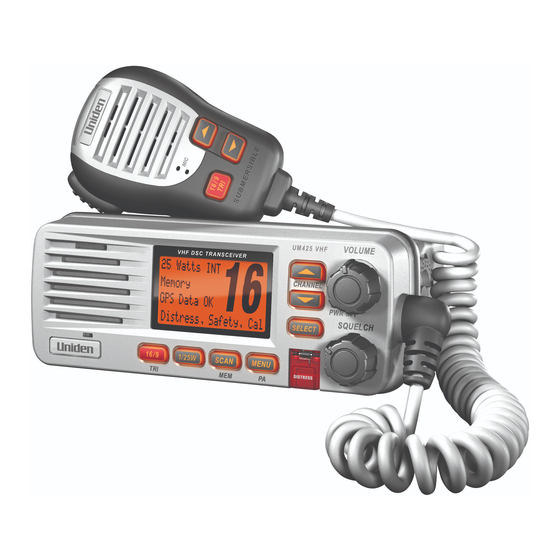
Getting Started Getting Started What's included UM425 VHF VHF DSC TRANSCEIVER 1 Watt Memory Scanning Channels 01,03,05,06,07,08 UM425 Radio DC Power Cable Accessory Cable Mounting Bracket and knobs Mounting Hardware Spare Fuse 250V 6A Microphone Hanger and Mounting Hardware... -
Page 9: Parts Of The Radio
Getting Started Parts of the radio Antenna Accessory Heat sink connector connector (SO238) ANTENNA 13.8V DC Power connector Table 2 - Rear panel connector functions Connector Connects to For details, see Antenna connector External VHF antenna with Connecting the radio, a male PL259 (SO238) page 44. -
Page 10: Table 3 - Front Panel Button Functions
Getting Started VOLUME (power) knob SELECT (turn clockwise button to increase display volume) & CHANNEL UP buttons DOWN Microphone cord UM425 VHF VHF DSC TRANSCEIVER 1 Watt Memory Scanning Channels 01,03,05,06,07,08 1/25W knob MENU SQUELCH button (public (turn clockwise 16/9- address) to decrease (triple/... -
Page 11: Table 4 - Microphone Button Functions
Getting Started Button Press to... Press and hold to... Change the transmit power (see 1/25W page 20). Display the radio menu. Use the public address MENU-PA (PA) function. Start scanning the channels saved Save a channel into SCAN-MEM in memory. memory or remove a channel from memory. -
Page 12: Turning On The Radio
How It Works Turning on the radio Turn the knob clockwise to turn on the radio. As it powers on, VOLUME-PWR the radio displays the user MMSI number; if there is no MMSI set, the radio displays MMSI not entered. When it powers on, the radio selects the last channel used. -
Page 13: Normal Mode Operation
How It Works In addition to the two main operation modes, the UM425 also provides two differ- ent “watch” modes which you can activate during any of the two basic modes. In the watch modes, the radio briefly checks for activity on a specific channel, then returns to its previous mode. -
Page 14: Using The Radio In Normal Mode
How It Works Table 5 - Normal mode status messages Message Meaning GPS Data OK The radio is receiving valid GPS data. Check GPS The radio is not receiving valid GPS data: check the GPS status screen and the GPS connection. Input Position The radio has been unable to receive valid GPS data for at least four hours;... -
Page 15: Normal Mode With Triple And Dual Watch
How It Works Normal mode with Triple and Dual Watch If you activate Triple Watch while operating in normal mode, the radio checks channels 16 and 9 every two seconds; with Dual Watch turned on, the radio only checks channel 16. The radio will not check channels 16 or 9 while you are actively transmitting;... -
Page 16: Scan Mode
How It Works Scan mode You can save channels into memory and then use scan mode to monitor those channels. When the radio detects a signal on a channel, it pauses on that channel as long as the signal is received; when the transmission stops, the radio will continue scanning. -
Page 17: Scan Mode With Triple And Dual Watch
How It Works • To remove a channel from memory, set the radio to that channel, then press and hold the button for two seconds. Memory will no SCAN-MEM longer show on the display. • To activate scan mode, press the button. -
Page 18: Using Your Radio
Using Your Radio Using Your Radio To display the radio menu, press the button. The menu has the MENU-PA following options: MENU Individual DSC Call SELECT Group All Ships POS Request Position Send Test Directory Standby Receive Log Exit Setup USA/CAN/INT* SELECT Dual/TriWatch... -
Page 19: Making A Voice Mayday Call
Using Your Radio • The currently selected item is highlighted in reversed out text. ▲ • Press the button on the radio or the button on the CHANNEL UP microphone to move up a line in the menu; if you are at the top line in the menu, the cursor jumps to the bottom of the menu. -
Page 20: Changing The Channel
Using Your Radio While listening to a channel, adjust the knob until the noise is SQUELCH filtered out and you can only hear the transmission. If you switch to a channel with a lot of noise or with a weak transmission, you may need to adjust the squelch level again. -
Page 21: Choosing Triple Watch Or Dual Watch
Using Your Radio NOTE: By default, when you change to channel 16, the radio automatically boosts the power to 25 Watts. Be sure to change the power back to 1 Watt if you are not making an emergency transmission. Some channels limit the power of transmission to 1 Watt so that there is less interference between boaters attempting to use the channel at the same time. -
Page 22: Changing Display And Sound Options
Using Your Radio Changing display and sound options Contrast The UM425 display has 10 levels of contrast. To adjust the contrast, press while the radio is idle. Select System and then Contrast. Use MENU-PA buttons to change the contrast to your CHANNEL UP CHANNEL DOWN desired level then press the... - Page 23 Using Your Radio Display the menu and choose the Setup sub-menu. Select GPS Setup and then choose Position Set. The cursor highlights the hour. Use the CHANNEL UP CHANNEL buttons to set the displayed hours to match coordinated DOWN universal time (UTC, also call Greenwich Mean Time and Zulu Time). When the display matches UTC time, press the button.
-
Page 24: Using Digital Selective Calling (Dsc) Features
Using Digital Selective Calling (DSC) Features Using Digital Selective Calling (DSC) Features What is DSC? Digital Selective Calling or DSC is a standard that allows you to call other stations using their unique identification code (the Maritime Mobile Service Identity or MMSI number), just like you would call a phone number. To call another station, just enter that station’s MMSI number and choose the voice channel you want to talk on. -
Page 25: Getting An Mmsi Number
Using Digital Selective Calling (DSC) Features Getting an MMSI number In order to use DSC features, you must be assigned an MMSI number and program that number into your radio. There are two kinds of MMSI numbers: individual numbers for use by single boats and group numbers for use by fleets, boating organizations, event coordinators, etc. -
Page 26: Group Mmsi Number
Using Digital Selective Calling (DSC) Features Use the buttons to change the first of CHANNEL UP CHANNEL DOWN the nine digits; the button increases the number and the CHANNEL UP button decreases the number. CHANNEL DOWN When the first digit is correct, press the button. -
Page 27: Using The Directory
Using Digital Selective Calling (DSC) Features When the ninth digit is correct, press the button. The radio SELECT displays the new MMSI number and asks you to confirm. To save this MMSI number, select Yes. To cancel this MMSI number, select No. -
Page 28: Table 6 - Character And Text Entry Order
Using Digital Selective Calling (DSC) Features Table 6 - Character and text entry order button button CHANNEL UP CHANNEL DOWN Capital letters (A through Z) One blank space Lower-case letters (a through z) Numbers (0 through 9) Punctuation (/ ‘ + -) Punctuation (/ ‘... -
Page 29: Making Dsc Calls
Using Digital Selective Calling (DSC) Features Making DSC Calls There are essentially four different types of DSC voice calls: Call type What it does When to use it Distress Alerts all stations that you need In an emergency only. assistance and sends them your current position. -
Page 30: Calling A Single Station (Individual Call)
Using Digital Selective Calling (DSC) Features Suppose you are coordinating safety for a sailboat race. Before the race starts, you instruct all the racers to enter your group MMSI number into their radios. During the race: • Throughout the race, you use group calling to update the racers on the time, race status, and any course corrections. -
Page 31: Calling A Particular Group Of Stations (Group Call)
Using Digital Selective Calling (DSC) Features • When the other station accepts the call, both radios switch to the se- lected response channel for voice transmission. • If the other station cannot respond on the channel you selected, the radio displays Not support CH. Calling a particular group of stations (Group Call) Group calling calls all the stations that share your group MMSI. -
Page 32: Making An Automatic Distress Call
Using Digital Selective Calling (DSC) Features Making an automatic distress call If you have programmed your MMSI number, the UM425 can transmit an automated distress call with your current location and nature of the distress. The radio then monitors the channel 16 for a response and repeats the distress call every few minutes until it receives an acknowledgement. -
Page 33: Receiving A Dsc Call
Using Digital Selective Calling (DSC) Features Receiving a DSC call If your radio receives an individual DSC call from another station, it sounds an incoming call tone and displays the name or MMSI number of the station calling you. To respond to the call, select Send: Able-Comply; the radio sends an acknowledgement and automatically switches to the designated response channel. -
Page 34: Returning A Call
Using Digital Selective Calling (DSC) Features Table 7 - Receive Log DSC Call Type Receive Log Information Distress MMSI (or name), position, time, nature code. Distress Acknowledge MMSI (or name), distress MMSI, position, time, nature code. Distress Relay MMSI (or name), distress MMSI, position, time, nature code. -
Page 35: Making A Test Call (Test)
Using Digital Selective Calling (DSC) Features Making Test Calls (Test) You can use the test call feature to make sure your radio is working and configured correctly. To avoid overloading coastal receiving stations, you should limit test calls to these stations to once a week. NOTE: Many coastal stations have specific frequencies and MMSI numbers you should use for making test calls. -
Page 36: Receiving A Test Call
Using Digital Selective Calling (DSC) Features When the other station acknowledges Test the test call, the radio displays an ac- Acknowledged knowledgement screen. 123456789 Completed Receiving a test call Test When another station sends you a test call, 123456789 the radio displays the test request screen: Reply To acknowledge the test call, select Reply Cancel... -
Page 37: Receiving A Position Request (Position Reply)
Using Digital Selective Calling (DSC) Features Press the button to display the menu. MENU-PA Choose the DSC Call sub-menu, then select POS Request. The radio displays the names listed in your directory; use CHANNEL UP buttons to highlight the directory entry you want to CHANNEL DOWN contact and press the button. -
Page 38: Sending Your Own Position (Position Send)
Using Digital Selective Calling (DSC) Features Press the button to display the menu. MENU-PA Select Setup and then POS Reply. Highlight Auto and press the button. The radio will SELECT automatically transmit your position when it receives a position request. To disable automatic position reply, repeat the steps above and select Manual. -
Page 39: Disabling Automatic Channel Switching
Using Digital Selective Calling (DSC) Features 1 Watt MENU DSC Call Memory SELECT Standby DSC Standby SELECT Unattended Display the menu and choose the DSC Call sub-menu. Select Standby to place your radio in standby mode. The radio displays the standby screen, above. To cancel standby and return to the mode your radio was in, press any button. -
Page 40: Renaming Channels
Renaming Channels Renaming Channels If you discover that a marine radio channel has a different common name in your local area, you can change the name of that channel to make it easier for you to use (see the channel list on page 57 for the default channel names). -
Page 41: Installing The Hardware
Installing the Hardware Installing the Hardware Mounting the radio The UM425 can sit at any angle in the mounting bracket so it can easily accommodate the best location. First, determine the best place to mount the radio. For optimum performance, find a location that can: •... - Page 42 Installing the Hardware Position the radio into the desired location. Mark the edges of the bracket on the mounting surface. Remove the mounting bracket drill template from the back of the manual, and use the template to mark the drill holes on the mounting surface.
-
Page 43: Connecting The Radio
Installing the Hardware Connecting the radio To operate correctly, your UM425 requires two electrical connections: • providing it with power from the boat’s electrical system • connecting a VHF-FM marine antenna to the antenna connector Power supply requirements VHF antenna requirements Nominal 13.8 VDC power supply with Male PL-259 connector a negative ground (10.8 VDC to 15.6... - Page 44 Installing the Hardware Connect the BLACK wire of the included power cable to the NEGATIVE (-) side of your power source. Connect the RED wire of the included power cable to the POSITIVE (+) side of your power source. power cable to the power connector on the back of the Connect the UM425.
-
Page 45: Connecting Accessories
Installing the Hardware Connecting accessories Connecting to a GPS receiver If you connect the radio to a GPS receiver, the radio can automatically transmit your current position during an automated distress call or during a normal DSC call. The UM425 supports a standard NMEA0183 input from a GPS receiver. Follow the steps below to connect the UM425 to your GPS receiver: Accessory connector... -
Page 46: Table 8 - Common Gps Receivers And Connections
Installing the Hardware Table 8 - Common GPS receivers and connections GPS NMEA0183 OUTPUT Wire Color Ground Wire Color (Connect to GREEN WIRE (connect to BARE GPS Manufacturer Model Number(s) on UM425) WIRE on UM425) Furuno GP1650, GP1850 White Black Furuno GP30, GP36 White... -
Page 47: Configuring The Gps
Installing the Hardware When the GPS receiver is correctly connected, the display shows GPS Data OK. If there is a problem with the GPS connection, the display shows Check GPS. When the display shows GPS Data OK, press the button to SELECT open the GPS status screen and see detailed GPS data: Time... -
Page 48: Connecting To A Charplotter
Installing the Hardware If Daylight Savings Time is currently in effect, select On. If Daylight Savings Time is not currently in effect, select Off. Press the button. The radio activates the new time setting and SELECT returns to the GPS Setup menu. Connecting to a charplotter The UM425 provides a standard NMEA0183 GPS output that you can connect to a chartplotter. -
Page 49: Connecting To An External Pa Speaker
Installing the Hardware Disconnect the accessory cable from the accessory connection on the radio. Connect the BLACK wire of the accessory cable to the GROUND WIRE of your external speaker. Connect the RED wire of the accessory cable to the POSITIVE (+) WIRE of your external speaker. -
Page 50: Using The Pa Feature
Installing the Hardware Using the PA feature Press and hold the MENU- button for two seconds to activate the PA feature. The display shows PA in the upper right hand corner. Public Address Press and hold the microphone Mode Selected button. -
Page 51: Maintenance And Troubleshooting
If the antenna has been damaged, you should not transmit except in the case of an emergency. A defective antenna may cause damage to your radio. • You should arrange for periodic performance checks with your Uniden dealer. Common questions Problem Things to Try The radio won’t power on. - Page 52 Where can I find my radio’s Look on the bottom side of the radio serial number? The radio won’t let me enter Contact customer service by visiting the customer my User MMSI. What do I do? support page on www.uniden.com.au or www.uniden.co.nz.
-
Page 53: Engine Noise Suppression
Maintenance and Troubleshooting Engine Noise Suppression Interference from the noise generated by the electrical systems of engines is sometimes a problem with radios. The UM425 has been designed to be essentially impervious to ignition noise and alternator noise. However, in some installations it may be necessary to take measures to further reduce the effect of noise interference. -
Page 54: Specifications
Specifications Specifications Table 9 - Radio specifications (All specifications are subject to change without notice.) General Controls , Squelch OLUME Status Indicators Transmit power, Scan mode, Triple Watch mode, Battery High, Battery low, USA, CAN, INT, Memory, GPS status and Channel Display Display LCD (Full Dot Matrix) Buttons... - Page 55 Specifications Transmitter Power Output 1 watt or 25 watt (user selectable) Power Requirement 25 watts output: 6A@13.8V DC Modulation ±5 kHz deviation Hum and Noise Signal-to-Noise 45 dB with 3 kHz deviation with 1000 Hz modulating frequency (nominal) Audio Distortion Less than 8% with 3 kHz deviation with 1000 Hz modulating frequency Spurious Suppression...
- Page 56 Specifications...
-
Page 57: Channel And Frequencies
Specifications Channel and frequencies Table 10 - International Channel Frequencies and Channel Tag Ch No. RX Freq TX Freq Status Full Name 160.6500 156.0500 Duplex Marine operator 160.7000 156.1000 Duplex Marine operator 160.7500 156.1500 Duplex Marine operator 160.8000 156.2000 Duplex Marine operator 160.8500 156.2500... - Page 58 Specifications Table 10 - International Channel Frequencies and Channel Tag (cont'd) Ch No. RX Freq TX Freq Status Full Name 156.5750 156.5750 Simplex Non commercial 156.6250 156.6250 Simplex Non commercial 156.6750 156.6750 Simplex Port operation 156.7250 156.7250 Simplex Port operation 156.7750 156.7750 Simplex, 1W...
-
Page 59: Table 11 - Usa Channel Frequencies And Channel Tag
Specifications Table 11 - USA Channel Frequencies and Channel Tag Ch No. RX Freq (MHz) TX Freq (MHz) Status Full Name Vessel traffic system/ 1 “A” 156.0500 156.0500 Simplex Commercial Vessel traffic system / 5 “A” 156.2500 156.2500 Simplex Commercial 156.3000 156.3000 Simplex... - Page 60 Specifications Table 11 - USA Channel Frequencies and Channel Tag (cont'd) Ch No. RX Freq (MHz) TX Freq (MHz) Status Full Name 156.825 156.8250 Simplex, 1W Port operation 156.8750 156.8750 Simplex, 1W Port operation (ship-ship) 78 “A” 156.9250 156.9250 Simplex Non commercial 79 “A”...
-
Page 61: Table 12 - Canadian Channel Frequencies And Channel Tag
Specifications Table 12 - Canadian Channel Frequencies and Channel Tag Ch No. RX Freq TX Freq Status Full Name 160.6500 156.0500 Duplex Marine operator 160.7000 156.1000 Duplex Marine operator 160.7500 156.1500 Duplex Marine operator 4 “A” 156.2000 156.2000 Simplex Canadian coast guard 5 “A”... - Page 62 Specifications Table 12 - Canadian Channel Frequencies and Channel Tag (cont'd) Ch No. RX Freq TX Freq Status Full Name 156.5750 156.5750 Simplex Non commercial 156.6250 156.6250 Simplex Non commercial 156.6750 156.6750 Simplex Port operation 156.7250 156.7250 Simplex Port operation 156.7750 156.7750 Simplex, 1W...
-
Page 63: Nmea Operation
Specifications NMEA Operation This radio supports NMEA0183 version 3.01. NMEA Input If you have difficulty getting the UM425 to receive data from your GPS receiver, check the device’s configuration. It should be set to the parameters shown in the table below. Table 13 - NMEA Input Parameters The radio supports RMC, GLL, GNS, Baud rate... -
Page 64: Regulations And Safety Warnings
Regulations and Safety Warnings Regulations and Safety Warnings Basic radio guidelines You should familiarize yourself with the rules on marine radios and be aware of which rules apply to your boat. DSC: Frequently Asked Questions The following information is sourced from the Australian Maritime Safety Authority's DSC FAQ. -
Page 65: Antenna Selection And Installation
Regulations and Safety Warnings How can a MMSI be applied for? The Australian Maritime Safety Authority allocates MMSI. To apply for an MMSI complete the MMSI Application form available for download via www.amsa.gov.au/mmsi. This page has important information about MMSI and DSC radio. -
Page 66: Two Year Limited Warranty
Australia or New Zealand and will expire two (2) years from the date of the original retail sale. If a warranty claim is made, this warranty will not apply if the Product is found by Uniden to be: (A) Damaged or not maintained in a reasonable manner or as recommended in the relevant Uniden Owner’s Manual;... -
Page 67: Mounting Bracket Template
Mounting Bracket Template 15.5 mm/ 18.5 mm/ 0.61 in 0.73 in ( 53 mm/ 2.1 in (2 3/32) 5.5 mm/ 0.2 in 7/32 8 mm /0.31 in 5/16... - Page 68 © 2011 Uniden Australia Pty Limited/Uniden New Zealand Limited Printed in PRC UTZZ01627ZA(0)
Need help?
Do you have a question about the UM425 VHF DSC and is the answer not in the manual?
Questions and answers