
Related Manuals for Uniden UM355


Summary of Contents for Uniden UM355
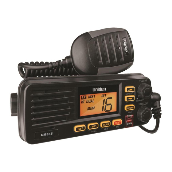
- Page 1 UM355 VHF Marine Radio For more exciting new products please visit our website: Australia: www.uniden.com.au...
-
Page 2: Making A Distress Call
Making a distress call Making a DISTRESS Call Speak slowly - clearly - calmly. For future reference, write your boat’s name & call sign here: 1. Make sure your radio is on. 2. On the radio, press the 16/67-Tri button to switch to Channel 16 (156.8 MHz). (If the corner of the display does not show 16, press the 16/67-Tri button again until it does.) 3. -
Page 3: Table Of Contents
Table of Contents (Cont'd) Table of Contents Making a DISTRESS Call......................2 Table of Contents ....................3 (this page) Introduction ..........................5 Features..........................5 Manual overview ........................5 Conventions .........................5 Getting Started ...........................6 What's included ..........................6 Parts of the radio ..........................7 Turning on the radio ........................ - Page 4 Table of Contents List of Tables Table 1 - Front panel button functions ..................7 Table 2 - Rear panel connector functions ................. 8 Table 3 - Microphone button functions ..................9 Table 4 - Radio specifications ....................26 Table 5 - International Channel Frequencies and Channel Tag .........
-
Page 5: Introduction
Introduction Introduction Features • Splashproof Meets the world standard JIS4 level. Being defined as no harmful influence by receiving a splash of water from any direction. • Large, LCD display • Memory scan mode Lets you save channels to memory and monitor them in quick succession. • Transmitter Power Level Select Lets you boost the transmitter power from 1 watt to 25 watts for added transmission distance. -
Page 6: Getting Started
Getting Started Getting Started What's included UM355 Radio Accessory Cable DC Power Cable Mounting Bracket and knobs Mounting Hardware Microphone Hanger and Flush Mount Bracket Mounting Hardware... -
Page 7: Parts Of The Radio
Getting Started VOLUME-PWR Parts of the radio CHANNEL UP & (power) knob CHANNEL DOWN (turn clockwise to LCD Display button increase volume) SIREN SQUELCH SCAN-MEM INST knob (turn clockwise 16/67-TRI WX-DUAL to decrease channel noise) 1W/25W-UIC Table 1 - Front panel button functions Button Press to... -
Page 8: Table 2 - Rear Panel Connector Functions
Getting Started Accessory Antenna connector Connector (SO238) Heat sink ANTENNA 13.8V DC Power Connector Table 2 - Rear panel connector functions Connector Connects to For details, see Antenna connector External VHF antenna with Connecting the radio, a male PL259 (SO238) page 21. -
Page 9: Table 3 - Microphone Button Functions
Getting Started PUSH-TO-TALK Button Table 3 - Microphone button functions Button Press to... Press and hold to... PUSH TO TALK Cancel scanning and stay on a Talk on a channel. channel. -
Page 10: Turning On The Radio
And Each of Scan mode, Triple/Dual Watch, EMG 16CH or 67CH mode and WX mode are canceled at this time. How It Works The UM355 has three basic modes of operation: Operation mode What it does: Use it when:... -
Page 11: Normal Mode Operation
How It Works In addition to the two main operation modes, the UM355 also provides two different “watch” modes which you can activate during any of the two basic modes. In the watch modes, the radio briefly checks for activity on a specific channel, then returns to its previous mode. -
Page 12: Using The Radio In Normal Mode
How It Works Using the radio in normal mode • To transmit, press and hold on the microphone. Release the button PUSH TO TALK when you are finished talking. • For the best sound quality, hold the microphone about two inches from your mouth while you’re talking. -
Page 13: Scan Mode
How It Works Scan mode You can save channels into memory and then use scan mode to monitor those channels. When the radio detects a signal on a channel, it pauses on that channel as long as the signal is received; when the transmission stops, the radio will continue scanning. -
Page 14: Scan Mode With Triple And Dual Watch
How It Works Scan mode with Triple and Dual Watch Press and hold (on the If you activate Triple Watch while 16/67-TRI WX-DUAL radio) for two seconds to turn Triple/Dual operating in scan mode, the radio Watch on or off. Press key to turn checks channels 16 and 67 every two SCAn-MEM... -
Page 15: Using Your Radio
Using Your Radio Using Your Radio Setting the Volume Turn the volume knob clockwise to increase the speaker volume; turn it counter- clockwise to decrease the volume. Setting the Squelch Level The squelch feature reduces the level of static on the speaker by filtering out the background channel noise. -
Page 16: Making A Transmission
Using Your Radio Making a transmission To make a transmission, press and hold the microphone button. PUSH TO TALK Release the button when you're finished talking to let the other party PUSH TO TALK respond. • To prevent stuck microphone problems or situations where the PUSH TO TALK button is pushed accidentally, the radio limits your talk time to 5 minutes in a single transmission. -
Page 17: Siren Out
Using Your Radio Press on a certain CH to toggle between the Instant CH and the previously INST selected channel. This key functions similar to the Emergency Channel 16CH and 67CH. Note: Pressing key in Tripe / Dual Watch, or Scan Mode, these mode are canceled INST and Instant CH is called in normal RX mode. -
Page 18: Installing The Hardware
Installing the Hardware Mounting the radio The UM355 can sit at any angle in the mounting bracket so it can easily accommodate the best location. First, determine the best place to mount the radio. For optimum performance, find a location that can: • Properly support the weight of the radio, approximately 2.2 pounds or 1.1... - Page 19 Installing the Hardware 2. Position the radio into the desired location. Mark the edges of the bracket on the mounting surface. 3. Remove the mounting bracket drill template from the back of the manual, and use the template to mark the drill holes on the mounting surface. 4.
-
Page 20: Installing Flush Mount Bracket
Installing the Hardware Installing the Flush Mount Bracket A FLUSH MOUNT is available for mounting the transceiver to a flat surface such as an instrument panel. CAUTION: KEEP the transceiver and microphone at least 1 meter away from your vessel’s magnetic navigation compass. -
Page 21: Connecting The Radio
Installing the Hardware Connecti ng the radio To operate correctly, your UM355 requires two electrical connections: • providing it with power from the boat’s electrical system • connecting a VHF-FM marine antenna to the antenna connector Power supply requirements VHF antenna requirements Nominal 13.8 VDC power supply with... - Page 22 2. Connect the RED wire of the included power cable to the POSITIVE (+) side of your power source. 3. Connect the power cable to the power connector on the back of the UM355. (The power connector only fits one way.) 4.
-
Page 23: Connecting Accessories
If you adjust the knob on the radio, it will VOLUME-PWR also adjust the external speaker volume. The UM355 supports an external speaker with the following specifications: • Minimum impedance of 4 Ohms • Minimum power handling of 10 Watts Accessory... -
Page 24: Maintenance And Troubleshooting
Maintenance and Troubleshooting Maintenance and Troubleshooting Due to its rugged design, the UM355 requires very little maintenance. However, it is a precision electronic instrument, so you should follow a few precautions: • If the antenna has been damaged, you should not transmit except in the case of an emergency. -
Page 25: Engine Noise Suppression
Engine noise Suppression Interference from the noise generated by the electrical systems of engines is sometimes a problem with radios. The UM355 has been designed to be essentially impervious to ignition noise and alternator noise. However, in some installations it may be necessary to take measures to further reduce the effect of noise interference. -
Page 26: Specifications
Specifications Specifications Table 4 - Radio specifications (All specifications are subject to change without notice.) General Controls Volume-Pwr, Squelch Status Indicators Transmit power, Scan mode, Triple Watch mode, Dual Watch mode, Battery High, Battery low, USA, CAN, INT, Memory, Message, Weather band and Channel Display Display Buttons 1W/25W/UIC, Channel UP, Channel DOWN, INST, WX-DUAL, 16/67-TRI, SIREN, and SCAN/MEM Connectors and Cables... - Page 27 Specifications General Audio Distortion Less than 8% with 3 kHz deviation with 1000 Hz modulating frequency Spurious Suppression –45 dBm @ Hi, –55 dBm @ Lo Output Power Stabilization Built-in automatic level control (ALC) Frequency Range 156 to 158 MHz Frequency Stability ±1.5kHz @ –15°C to + 55°C Receiver...
- Page 28 Flush Mount Bracket - Recommended size...
-
Page 29: Channel And Frequencies
Specifications Channel and frequencies Table 5 - International Channel Frequencies and Channel Tag Ch no. RX Freq TX Freq Status Full name 160.6500 156.0500 Duplex Marine operator 160.7000 156.1000 Duplex Marine operator 160.7500 156.1500 Duplex Marine operator 160.8000 156.2000 Duplex Marine operator 160.8500 156.2500... - Page 30 Specifications Table 5 - International Channel Frequencies and Channel Tag (cont'd) Ch no. RX Freq TX Freq Status Full name 156.5750 156.5750 Simplex Non commercial 156.6250 156.6250 Simplex Non commercial 156.6750 156.6750 Simplex Port operation 156.7250 156.7250 Simplex Port operation 156.7750 156.7750 Simplex, 1W...
-
Page 31: Table 6 - Usa Channel Frequencies And Channel Tag
Specifications Table 6 - USA Channel Frequencies and Channel Tag Ch no. RX Freq (MHz) TX Freq (MHz) Status Full name Vessel traffic system/ 1 “A” 156.0500 156.0500 Simplex Commercial Vessel traffic system / 5 “A” 156.2500 156.2500 Simplex Commercial 156.3000 156.3000 Simplex Inter-ship safety 7 “A”... - Page 32 Specifications Table 6 - USA Channel Frequencies and Channel Tag (cont'd) Ch no. RX Freq (MHz) TX Freq (MHz) Status Full name 156.825 156.8250 Simplex, 1W Port operation 156.8750 156.8750 Simplex, 1W Port operation (ship-ship) 78 “A” 156.9250 156.9250 Simplex Non commercial 79 “A”...
-
Page 33: Table 7 - Canadian Channel Frequencies And Channel Tag
Specifications Table 7 - Canadian Channel Frequencies and Channel Tag Ch no. RX Freq TX Freq Status Full name 160.6500 156.0500 Duplex Marine operator 160.7000 156.1000 Duplex Marine operator 160.7500 156.1500 Duplex Marine operator 4 “A” 156.2000 156.2000 Simplex Canadian coast guard 5 “A”... - Page 34 Specifications (cont'd) Table 7- Canadian Channel Frequencies and Channel Tag Ch no. RX Freq TX Freq Status Full name 156.5750 156.5750 Simplex Non commercial 156.6250 156.6250 Simplex Non commercial 156.6750 156.6750 Simplex Port operation 156.7250 156.7250 Simplex Port operation 156.7750 156.7750 Simplex, 1W Port operation...
-
Page 35: Regulations And Safety Warnings
Regulations and Safety Warnings Antenna Selection and Installation Your UM355 has been designed to accommodate all of the popular marine VHF antennas. However, the selection and the proper installation of the antenna is the responsibility of the user or installer. -
Page 36: Two Year Limited Warranty
Accessories 1 Year If a warranty claim is made, this warranty will not apply if the Product is found by Uniden to be: (A) Damaged or not maintained in a reasonable manner or as recommended in the relevant Uniden Owner’s Manual;... -
Page 37: Mounting Bracket Template
Mounting Bracket Template 15.5 mm/ 18.5 mm/ 0.61 in 0.73 in ( 53 mm/ 2.1 in (2 3/32) 5.5 mm/ 0.2 in 7/32 8 mm /0.31 in 5/16... - Page 40 © 2014 Uniden Australia Pty Limited Printed in Vietnam U01UT651ZZZ(0)
Need help?
Do you have a question about the UM355 and is the answer not in the manual?
Questions and answers
does the uniden 355 have a fuse inside it?