
Related Manuals for Uniden UM435


Summary of Contents for Uniden UM435
- Page 1 UM435 SUBMERSIBLE DSC MARINE RADIO RADIO MARITIME ASN SUBMERSIBLE OWNER’S MANUAL GUIDE D’UTILISATION...
-
Page 2: Making A Voice Distress Call
MAKING A DISTRESS CALL Lift the red cover. Press and hold the DISTRESS button for three seconds. Your radio transmits your boat’s location every few minutes until you receive a response. If the radio displays Enter User MMSI, cancel the automatic distress NOTE: Lift the red cover call and make a normal voice distress call. -
Page 3: Faire Un Appel De Détresse Vocal
FAIRE UN APPEL DE DÉTRESSE Soulevez le couvercle rouge. Maintenez la touche DISTRESS enfoncée pendant trois secondes. Votre radio transmet l’emplacement de votre bateau toutes les quelques minutes jusqu’à ce qu’il reçoive une réponse. # REMARQUE : Si la radio affiche Enter User MMSI (Entrer l’ISMM de Soulvez le couvercle rouge et appuyez sur le l’utilisateur), annulez l’appel de détresse automatique et faites un... -
Page 4: Cómo Hacer Una Llamada De Socorro Por Voz
14. Suelte el botón PUSH TO TALK y escuche. Si no recibe una contestacion dentro de 30 segundos, repita su llamada, comenzando con el paso 3, descrito arriba. Visite www.uniden.com para bajar el manual en español de la radio UM435. -
Page 5: Table Of Contents
CONTENTS MAKING A VOICE DISTRESS CALL ................II FAIRE UN APPEL DE DÉTRESSE VOCAL ..............III CÓMO HACER UNA LLAMADA DE SOCORRO POR VOZ ........IV INTRODUCTION ................. 1 FEATURES ......................1 EXPLANATION OF TERMS ..................1 GETTING STARTED ................2 WHAT’S INCLUDED ....................2 PARTS OF THE RADIO ................... - Page 6 SETTING THE GPS POSITION MANUALLY ............14 USING DIGITAL SELECTIVE CALLING (DSC) FEATURES ....15 WHAT IS DSC? ...................... 15 ADVANCED DSC FEATURES ................. 15 WHAT IS AN MMSI NUMBER? ................16 ENTERING MMSI NUMBERS ................16 Individual or User MMSI Number ..............16 Group MMSI number ..................
- Page 7 CONNECTING TO A CHARTPLOTTER ..............31 CONNECTING TO AN EXTERNAL SPEAKER ............32 MAINTENANCE AND TROUBLESHOOTING ........33 ENGINE NOISE SUPPRESSION ................34 SPECIFICATIONS ................35 RADIO SPECIFICATIONS ..................35 REFERENCE TABLES ................. 36 CHANNEL DESCRIPTIONS AND WHAT THEY MEAN ..........36 MARINE RADIO CHANNEL CHART ................
-
Page 9: Introduction
INTRODUCTION FEATURES x Submersible Design – Complies with IPX8 submersible standards, which means the radio can be submerged in 1.5 meter of water for 30 minutes without damage. x Large, dot matrix display x Advanced DSC Class D functions, including Test Calling x Channel select buttons on the microphone x Memory scan mode –... -
Page 10: Getting Started
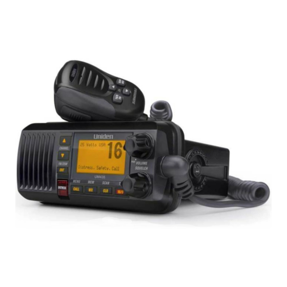
GETTING STARTED WHAT’S INCLUDED Mounting Hanger and Mounting Bracket and Knobs Mounting Hardware Mounting Hardware DC Power Cable Accessory Cable PARTS OF THE RADIO CHANNEL UP & VOLUME-PWR (power knob - turn clockwise to 1W/25W CHANNEL DOWN display increase volume) button button CLR-SCAN... - Page 11 Button Press to... Press and hold to... Choose an option on a menu or Change the transmit power (see ENT-1W/25W to display the GPS data. page 12). Move up one channel at a time. Move quickly up the channels. CHANNEL UP Move down one channet at a CHANNEL Move quickly down the channels.
-
Page 12: Parts Of The Microphone
PARTS OF THE MICROPHONE Button Press to... Press and hold to... Move up one channel Move quickly up the at a time. channels. Move down one Move quickly down the channel at a time. channels. Push to Talk button 1st press: Go to Microphone Channel 16. -
Page 13: How It Works
HOW IT WORKS Your radio has three basic modes of operation: To Turn it on/ Mode What It Does Use It When off... Monitors a single marine radio channel You want to talk to another Normal (default mode) and lets you talk on station on a specific channel. -
Page 14: Using The Radio In Normal Mode
Message Meaning GPS Data The radio is receiving valid GPS data. The radio is not receiving valid GPS data: check the GPS status Check GPS screen and the GPS connection. The radio has been unable to receive valid GPS data for at Input least four hours;... -
Page 15: Normal Mode With Triple Or Dual Watch
Normal mode with Triple or Dual Watch If you activate Triple Watch while operating in normal mode, the radio checks channels 16 and 9 every two seconds; with Dual Watch turned on, the radio only checks channel 16. The radio will not check channels 16 or 9 while you are actively transmitting; it waits until your transmission is finished and then checks the channels. -
Page 16: Using The Radio In Scan Mode
In scan mode, you can get the following information from the display (some indicators will not always be displayed). Using the radio in scan mode x You cannot transmit while in scan mode. x You must have two or more channels in memory to start a scan. x To save a channel into memory, select the channel, then press and hold WX-MEM for two seconds. -
Page 17: Weather Mode
Scan mode with Triple or Dual Watch If you activate Triple Watch while operating in scan mode, the radio checks channels 16 and 9 every two seconds, then goes on to scan the next channel; with Dual Watch turned on, the radio only checks channel 16. Press and hold 16/9-TRI (on the radio or the microphone) for two seconds to turn Triple or Dual Watch on or off. -
Page 18: Using The Radio In Weather Mode
Using the radio in weather mode x You cannot transmit while in weather mode. x To enter weather mode, press WX-MEM. x Weather mode can filter out alerts that do not affect your location if the location code (FIPS code) of the alert is entered in your radio (see page 13). If you have no FIPS codes programmed into your radio, the radio will notify you of all alerts in any area. -
Page 19: Using Your Radio
CALL 1W/2.5 W 1W/2.5 W 1W/2.5 W Using Your Radio x An arrow on the left side indicates the current selection. x Press CHANNEL UP on the radio or the microphone to move up a line in the menu; if you are at the top line in the menu, the cursor jumps to the bottom of the menu. -
Page 20: Changing The Channel
While listening to a channel, adjust the SQUELCH knob until the noise is filtered out and you can only hear the transmission. If you switch to a channel with a lot of noise or with a weak transmission, you may need to adjust the squelch level again. # NOTE: Setting the squelch level too high may prevent you from hearing weaker transmissions. -
Page 21: Choosing Triple Watch Or Dual Watch
Some channels (for example, channels 13 and 67) limit the power of transmission to 1 Watt so that there is less interference between boaters attempting to use the channel at the same time. If you switch to one of these channels, the radio changes back to 1 Watt automatically. -
Page 22: Changing Display And Sound Options
1W/2.5 W 1W/2.5 W 1W/2.5 W Display the normal menu and choose the Setup sub-menu. 2. Select FIPS Codes. The screen displays any previously-entered FIPS codes. 3. To add a new FIPS code, select New. 4. Use CHANNEL UP and CHANNEL DOWN to change the first of the six digits; CHANNEL UP increases the number and CHANNEL DOWN decreases it. -
Page 23: Using Digital Selective Calling (Dsc) Features
# NOTE: Be certain any manually-entered position is correct. If you enter the wrong position and then make a DSC distress call, you will be telling the arrows to adjust each of the values in turn. CALL 1W/25W 1W/25W 1W/25W 1. -
Page 24: What Is An Mmsi Number
Feature Menu Item Function Contact another vessel from your Individual Call Individual directory. Contact all vessels that share your group Group Call Group MMSI code. Broadcast to all vessels within range (used All Ships Call All Ships for safety or advisory messages). Request the current location of another Position Request POS Request vessel. -
Page 25: Group Mmsi Number
CALL 1W/25W 1W/25W 1W/25W Display the normal menu and choose the Setup sub-menu. 2. Select User MMSI. (If an MMSI number was already entered, the screen displays it with the message Cannot change over 1 time. Visit our website at www. unidensupport.com for help.) 3. -
Page 26: Using The Directory
6. To save this MMSI number, select Yes and confirm the entry. To cancel this MMSI number, select No. The radio returns to the Setup menu. USING THE DIRECTORY The directory lets you store up to 20 MMSI numbers of other stations so you can call them quickly. -
Page 27: Making Dsc Calls
9. When you finish entering the name, the radio displays the new MMSI number and name and asks you to confirm. To save this directory entry, select Yes; to cancel this directory entry, select No. The radio returns to the directory list. 10. -
Page 28: Calling A Single Station (Individual Call)
Calling a single station (Individual Call) To call a single station with DSC, follow the steps below: 1. Press CALL-MENU to display the call menu. 2. Select Individual. 3. The radio displays the names listed in your directory; use CHANNEL UP and CHANNEL DOWN to choose the directory entry you want to call and press ENT-1W/25W. -
Page 29: Calling All Stations (All-Ships Call)
3. The radio prompts you to select a response channel. Use CHANNEL UP and CHANNEL DOWN to scroll through the available channels. When you reach the channel you want to use for a response, press ENT-1W/25W. 4. The radio asks you to confirm the call. Select Send to continue with the call or select Cancel to cancel the call. -
Page 30: Canceling An Automatic Distress Call
Canceling an automatic distress call While the radio is waiting for a response, it gives you the option of canceling the call. To cancel the distress call, choose Cancel and press ENT-1W/25W. RECEIVING A DSC CALL If your radio receives an individual DSC call from another station, it sounds an incoming call tone and displays the name or MMSI number of the station calling you. -
Page 31: Returning A Call
DSC Call Receive Log Information Type Distress MMSI (or name), distress MMSI, position, time, nature code. Acknowledge Distress Relay MMSI (or name), distress MMSI, position, time, nature code. Distress Relay MMSI (or name), distress MMSI, position, time, nature code. Acknowledge Geographical MMSI (or name), category code, communication channel number. -
Page 32: Receiving Test Calls
Enter all nine digits and press ENT-1W/25W button. 4. The radio displays the MMSI number you are about to call and asks you to confirm. If you want to call the displayed number, select Send. To cancel the call, select Cancel. 5. -
Page 33: Position Request And Reply
3. To disable automatic test call reply, repeat the steps above and select Manual. POSITION REQUEST AND REPLY Requesting another station’s position (POS Request) Anytime you need to know where another boat currently is—to find your boating partners, to respond to a request for assistance, etc.—you can send a position request to their radio: 1. -
Page 34: Enabling Automatic Position Reply
Enabling automatic position reply If you want the radio to automatically transmit your current position whenever it receives a position request, you can enable automatic position reply. Most boaters activate automatic position reply for safety reasons or because they subscribe to a marine towing service. -
Page 35: Disabling Automatic Channel Switching
3. To cancel standby and return to the mode your radio was in, press any button. DISABLING AUTOMATIC CHANNEL SWITCHING If you are involved in a bridge-to-bridge call, you may not want the radio to automatically switch channels when it receives a DSC call. In cases like this, you can disable automatic channel switching. -
Page 36: Installing The Hardware
INSTALLING THE HARDWARE MOUNTING THE RADIO Your radio can sit at any angle in the mounting bracket so it can easily accommodate the best location. First, determine the best place to mount the radio. For optimum performance, find a location that can: x Properly support the weight of the radio, approximately 2.2 pounds or 1.0 kilograms. -
Page 37: Connecting The Radio
CONNECTING THE RADIO To operate correctly, your radio requires two electrical connections: x providing it with power from the boat’s electrical system x connecting a VHF-FM marine antenna to the antenna connector Power Supply Requirements VHF Antenna Requirements Male PL-259 connector Nominal 13.8 VDC power supply with a 50 Ω... -
Page 38: Connecting The Accessory Cable
CONNECTING THE ACCESSORY CABLE Use the accessory cable to connect the radio to a GPS receiver, a GPS chartplotter, and an external speaker. The wiring diagram below shows the connections for each accessory. ACCESSORY CABLE WIRES CONNECTS TO... Brown: NMEA_OUT NMEA Data Input (-) on Chartplotter Green: NMEA_IN (-) NMEA Data Output (-) or GND from GPS receiver... -
Page 39: Configuring The Gps
After 4 hours, the audible alert sounds again if no coordinates are received and the GPS is connected. After 23.5 hours, the radio deleted the current coordinates and displays Input GPS. See page 14 to manually set the GPS coordinates. Configuring the GPS If the radio is receiving valid GPS data, it will automatically set the clock to your local time based on the GPS location. -
Page 40: Connecting To An External Speaker
CONNECTING TO AN EXTERNAL SPEAKER You can use an external speaker to monitor the radio from a different part of your boat or in a noisy environment. If you adjust the VOLUME-PWR knob on the radio, it will also adjust the external speaker volume. -
Page 41: Maintenance And Troubleshooting
MAINTENANCE AND TROUBLESHOOTING Due to its rugged design, your radio requires very little maintenance. However, it is a precision electronic instrument, so you should follow a few precautions: x If the antenna has been damaged, you should not transmit except in the case of an emergency. -
Page 42: Engine Noise Suppression
The radio won’t let me enter my User MMSI. What do I Visit our website at www.uniden.com for assistance. ENGINE NOISE SUPPRESSION Interference from the noise generated by the electrical systems of engines is sometimes a problem with radios. -
Page 43: Specifications
SPECIFICATIONS All specifications are subject to change without notice. RADIO SPECIFICATIONS General Controls Volume-Pwr, Squelch Transmit power, Scan mode, Triple Watch mode, Battery Status Indicators High, Battery low, USA, CAN, INT, Alert, Memory, GPS, Message, Weather band, GPS status and Channel Display Display LCD (Full Dot Matrix) ENT-1W/25W, Channel UP, Channel DOWN, CALL-... -
Page 44: Reference Tables
General 0.25 μV for 12 dB SINAD (nominal) Sensitivity Circuit Dual Conversion Super Heterodyne PLL (Crystal for DSC) 0.2 μV Threshold Squelch Sensitivity Spurious Response 75 dB (nominal) Adjacent Channel 70 dB @ ±25 kHz (nominal) Selectivity 2.5 watts (10% Distortion, 8 Ω load) Audio Output Power 360 mA @ 13.8V DC at squelched, 920 mA @ 13.8V DC at Power Requirement... -
Page 45: Marine Radio Channel Chart
Channel name/description Used for messages about government regulation and control, boating activities, or assistance to ships; STATE CONTROL also used to talk to ships and coast stations operated by state or local governments DSC signals only (no voice communications DIGITAL SELECTIVE CALLING allowed at any time) MARINE RADIO CHANNEL CHART CAN TX... - Page 46 CAN TX Channel Type/Name Intership Navigation Safety (Bridge-to-Bridge). Ships >20m 156.650 156.650 length maintain a listening watch on this channel in US waters. Port Operation, VTS in some 156.700 156.700 areas Inhibit 156.750 Environmental (Receive Only) Inter-ship, Port Operations, 156.750 156.750 Commercial, Non-Commercial, Ship Movement (1 Watt Only)
- Page 47 CAN TX Channel Type/Name Public Correspondence (Marine 157.300 161.900 Operator) Public Correspondence (Marine 157.350 161.950 Operator) Public Correspondence (Marine 157.400 162.000 Operator) Canadian CG Continuous Marine INHIBIT 162.000 Broadcast (CMB) Service Public Correspondence (Marine 156.025 160.625 Operator) Public Correspondence (Marine 156.075 160.675 Operator)
- Page 48 CAN TX Channel Type/Name Non-Commercial 156.475 156.475 Canada: Commercial East Coast. Non-Commercial West Coast DSC (Digital Selective Calling) 156.525 156.525 Only. No Voice Communications Allowed US: Non-Commercial Canada: Ship Movement West 156.575 156.575 Coast, Non-Commercial East Coast 156.625 156.625 Non-Commercial (Ship-to-Ship) 156.675 156.675 Port Operations...
-
Page 49: Weather Channels And Frequencies (Us, Can, And Int)
CAN TX Channel Type/Name Public Correspondence (Marine 157.425 157.425 Operator) 1019 156.950 156.950 Commercial 1020 157.000 157.000 Port Operations 1078 156.925 156.925 Non-Commercial, Inter-Ship 1079 156.975 156.975 Commercial, Inter-Ship 2019 161.550 161.550 Commercial 2020 161.600 161.600 Port Operations 2078 161.525 161.525 Port Operations 2079... - Page 50 SAME Event Type Code Blizzard Warning Warning Coastal Flood Watch Watch Coastal Flood Warning Warning Dust Storm Warning Warning Flash Flood Watch Watch Flash Flood Warning Warning Flash Flood Statement Statement Flood Watch Watch Flood Warning Warning Flood Statement Statement High Wind Watch Watch High Wind Warning...
-
Page 51: No Response Event Code
SAME Event Type Code Local Area Emergency Emergency 911 Telephone Outage Emergency Emergency Nuclear Power Plant Warning Warning Radiological Hazard Warning Warning Shelter in Place Warning Warning Volcano Warning Warning Test Message Test Practice/Demo Warning Test Required Monthly Test Test Required Weekly Test Test Biological Hazard Warning... -
Page 52: Nmea Operation
Transmitter Carrier On Transmitter Primary On NMEA OPERATION This radio supports NMEA0183 version 3.01. NMEA Input If you have difficulty getting your radio to receive data from your GPS receiver, check the device’s configuration. It should be set to the following parameters: Baud rate 4800 bps Data bits... -
Page 53: Regulations And Safety Warnings
REGULATIONS AND SAFETY WARNINGS MARITIME RADIO SERVICES OPERATION This transmitter will operate on channels/frequencies that have restricted use WARNING! in the United States. The channel assignments include frequencies assigned for exclusive use of the U.S. Coast Guard, use in Canada, and use in international waters. Operation on these frequencies without proper authorization is strictly forbidden. -
Page 54: Antenna Selection And Installation
à l’utilisateur de faire fonctionner cet équipement. ANTENNA SELECTION AND INSTALLATION Your UM435 has been designed to accommodate all of the popular marine VHF antennas. However, the selection and the installation of the antenna is the responsibility of the user or installer. - Page 55 (E) used in any conjunction with equipment or parts or as part of any system not manufac- tured by Uniden, or (F) installed or programmed by anyone other than as detailed by the Operating Guide for this product. STATEMENT OF REMEDY: In the event that the product does not conform to this warran-...
Need help?
Do you have a question about the UM435 and is the answer not in the manual?
Questions and answers