
Subscribe to Our Youtube Channel
Related Manuals for Uniden UM455


Summary of Contents for Uniden UM455
- Page 1 UM455 VHF DSC Marine Radio For more exciting new products please visit our website: Australia: www.uniden.com.au...
-
Page 2: Making A Dsc Distress Call
Making a DSC DISTRESS Call Lift the red cover. Press and hold the DISTRESS button for three seconds. The UM455 transmits your boat’s location every few minutes until you receive a response. NOTE: If the radio displays ENTER USER MMSI, cancel... - Page 3 Making a distress call...
-
Page 4: Table Of Contents
Table of Contents Table of Contents Making a DSC DISTRESS Call ....................2 Making a voice distress call ....................2 Table of Contents ....................4 (this page) Introduction ..........................6 Features..........................6 Manual overview ........................6 Conventions ........................ - Page 5 Table of Contents (Cont'd) Enabling automatic test call reply ..................36 Position request and reply ....................36 Requesting another station's position (POS Request) .............36 Receiving a position request (Position Reply) ..............37 Enabling automatic position reply ..................37 Sending your own position (Position Send) ................38 Putting the radio into standby..................
-
Page 6: Introduction
Introduction Introduction Features • Submersible Design: Complies with JIS8 water-resistant standards, which means the radio can be submerged in 1.5 meter of water for 30 minutes without damage. • Rugged Waterproof Speaker Microphone: With Channel Select, One-Touch 16/67 and Triple Watch Select Keys. Meets the worldwide JIS7 waterproof specifications;... -
Page 7: Terms Used In This Manual
Introduction Table 1 - Terms used in the manual Term Meaning Digital Selective Calling. A VHF radio standard for communicating among boats and sending automated distress calls. Weather Radio Global Positioning System National Marine Electronics Association. The organization that governs NMEA standards for electronic equipment used on boats. -
Page 8: Getting Started
Getting Started Getting Started What's included What's included UM455 Radio Accessory Cable DC Power Cable Mounting Bracket and knobs Mounting Hardware Microphone Hanger and Flush Mount Bracket Mounting Hardware... -
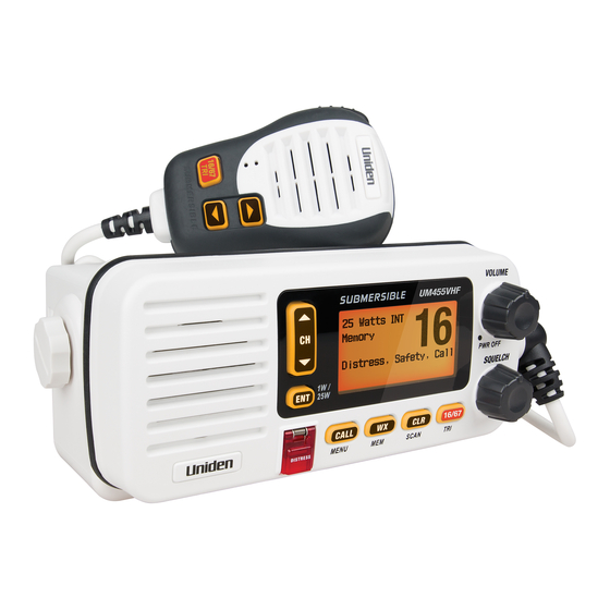
Page 9: Parts Of The Radio
Getting Started Parts of the radio Antenna Accessory Heat sink connector connector (SO238) ANTENNA 13.8V DC Power connector Table 2 - Rear panel connector functions Connector Connects to For details, see Antenna connector External VHF antenna with Connecting the radio, a male PL259 (SO238) page 44. -
Page 10: Table 3 - Front Panel Button Functions
Getting Started VOLUME-PWR (power) knob (turn clockwise ENT- 1W/25W CHANNEL UP & to increase LCD display button CHANNEL volume) DOWN button Microphone cord DISTRESS WX-MEM 16/67-TRI button button (triple/dual- watch) button CLR-SCAN SQUELCH knob CALL-MENU (channel (turn clockwise to button scan) button decrease channel noise) -
Page 11: Table 4 - Microphone Button Functions
Getting Started PUSH- TALK button ▲ (up) button (move up a channel) 16/67 16 / 9 ▼ (Triple/Dual- (down) button Watch) button (move down a channel) Table 4 - Microphone button functions Button Press to... Press and hold to... ▲ Move up one channel at a time. -
Page 12: Turning On The Radio
Mode), or international (Intl Mode). 4. Press . The radio activates the new channel mode and exits the menu. ENT-1W/25W How It Works The UM455 has two basic modes of operation: Operation mode What it does: Use it when: To turn it on/off:... -
Page 13: Normal Mode Operation
How It Works In addition to the two main operation modes, the UM455 also provides two different “watch” modes which you can activate during any of the two basic modes. In the watch modes, the radio briefly checks for activity on a specific channel, then returns to its previous mode. -
Page 14: Using The Radio In Normal Mode
How It Works Table 5 - Normal mode status messages Message Meaning GPS Data OK The radio is receiving valid GPS data. Check GPS The radio is not receiving valid GPS data: check the GPS status screen and the GPS connection. Input Position The radio has been unable to receive valid GPS data for at least four hours;... -
Page 15: Normal Mode With Triple And Dual Watch
How It Works Normal mode with Triple and Dual Watch If you activate Triple Watch while operating in normal mode, the radio checks channels 16 and 67 every two seconds; with Dual Watch turned on, the radio only checks channel 16. The radio will not check channels 16 or 67 while you are actively transmitting;... -
Page 16: Scan Mode
How It Works Scan mode You can save channels into memory and then use scan mode to monitor those channels. When the radio detects a signal on a channel, it pauses on that channel as long as the signal is received; when the transmission stops, the radio will continue scanning. -
Page 17: Scan Mode With Triple And Dual Watch
How It Works • To activate scan mode, press and hold . Press and hold again to CLR-SCAN CLR-SCAN return to the previous mode. • When the radio automatically stops on a channel, press to leave that CHANNEL UP channel and resume scanning. • To end the scan, press the microphone’s buttons. -
Page 18: Using Your Radio
Using Your Radio Using Your Radio To display the radio call menu, press . To display the radio normal menu, CALL-MENU press and hold . The menu has the following options: CALL-MENU Press and hold - Setup USA/CAN/INT Dual/TriWatch GPS Setup Auto CH SW POS Reply Test Reply... -
Page 19: Making A Voice Mayday Call
Using Your Radio • An arrow on the left side indicates the current selection. • Press on the radio or the microphone to move up a line in the menu; if CHANNEL UP you are at the top line in the menu, the cursor jumps to the bottom of the menu. • Press to choose the selected item. -
Page 20: Changing The Channel
Using Your Radio While listening to a channel, adjust the knob until the noise is filtered out SQUELCH and you can only hear the transmission. If you switch to a channel with a lot of noise or with a weak transmission, you may need to adjust the squelch level again. NOTE: Setting the squelch level too high may prevent you from hearing weaker transmissions. -
Page 21: Choosing Triple Watch Or Dual Watch
Using Your Radio Some channels limit the power of transmission to 1 Watt so that there is less interference between boaters attempting to use the channel at the same time. If you switch to one of these channels, the radio changes back to 1 Watt automatically. See the channel list on page 57 for a list of power-restricted channels. -
Page 22: Changing Display And Sound Options
Using Your Radio Changing display and sound options Contrast Your radio display has 10 levels of contrast. To adjust the contrast, press and hold while the radio is idle. Select System and then Contrast. Use CALL-MENU CHANNEL UP to change the contrast to your desired level. CHANNEL DOWN To restore the default contrast setting, turn the radio off. - Page 23 Using Your Radio 4. The cursor moves to highlight the minutes. Use CHANNEL UP CHANNEL DOWN adjust the minutes and press ENT-1W/25W 5. The cursor moves to highlight the degrees latitude. As you update each value, the cursor moves to the next value in turn. At each number, use CHANNEL UP to adjust the number and press CHANNEL DOWN...
-
Page 24: Using Digital Selective Calling (Dsc) Features
The DSC standard dedicates a VHF channel—channel 70—to digital transmissions only. Since digital transmissions require less bandwidth voice transmissions, channel 70 avoids the problems of busy voice channels. Advanced DSC features The UM455 supports the following DSC features: Feature Menu Item Function... -
Page 25: Getting An Mmsi Number
Using Digital Selective Calling (DSC) Features Getting an MMSI number In order to use DSC features, you must be assigned an MMSI number and program that number into your radio. There are two kinds of MMSI numbers: individual numbers for use by single boats and group numbers for use by fleets, boating organizations, event coordinators, etc. -
Page 26: Group Mmsi Number
Using Digital Selective Calling (DSC) Features 3. Use to enter the first of the nine digits; CHANNEL UP CHANNEL DOWN CHANNEL UP increases the number and decreases it. CHANNEL DOWN 4. When the first digit is correct, press . The cursor moves to the next ENT-1W/25W digit. -
Page 27: Using The Directory
Using Digital Selective Calling (DSC) Features Using the directory The directory lets you store up to 20 MMSI numbers of other stations so you can call them quickly. Follow the steps below to edit the MMSI numbers in your directory: Press Directory MMSI... -
Page 28: Table 6 - Character And Text Entry Order
Using Digital Selective Calling (DSC) Features Table 6 - Character and text entry order Channel Up Button Channel Down Button Capital letters (A through Z) One blank space Lower-case letters (a through z) Numbers (0 through 9) Punctuation (/ ‘ + -) Punctuation (/ ‘... -
Page 29: Making Dsc Calls
Using Digital Selective Calling (DSC) Features Making DSC Calls There are essentially four different types of DSC voice calls: Call type What it does When to use it Distress Alerts all stations that you need In an emergency only. assistance and sends them your current position. -
Page 30: Calling A Single Station (Individual Call)
Using Digital Selective Calling (DSC) Features Suppose you are coordinating safety for a sailboat race. Before the race starts, you instruct all the racers to enter your group MMSI number into their radios. During the race: • Throughout the race, you use group calling to update the racers on the time, race status, and any course corrections. -
Page 31: Calling A Particular Group Of Stations (Group Call)
Using Digital Selective Calling (DSC) Features Calling a particular group of stations (Group Call) Group calling calls all the stations that share your group MMSI. You must have a group MMSI programmed into the radio to make a group call, and the stations (boats) you are calling must have this same group MMSI programmed into their radios. -
Page 32: Making An Automatic Distress Call
Using Digital Selective Calling (DSC) Features Making an automatic distress call If you have programmed your MMSI number, your radio can transmit an automated distress call with your current location and nature of the distress. The radio then monitors the channel 16 for a response and repeats the distress call every few minutes until it receives an acknowledgement. -
Page 33: Receiving A Dsc Call
Using Digital Selective Calling (DSC) Features Receiving a DSC call If your radio receives an individual DSC call from another station, it sounds an incoming call tone and displays the name or MMSI number of the station calling you. To respond to the call, select Send: Able-Comply; the radio sends an acknowledgement and automatically switches to the designated response channel. -
Page 34: Returning A Call
Using Digital Selective Calling (DSC) Features Table 7 - Receive Log DSC Call Type Receive Log Information Distress MMSI (or name), position, time, nature code. Distress MMSI (or name), distress MMSI, position, time, nature code. Acknowledge Distress Relay MMSI (or name), distress MMSI, position, time, nature code. Distress Relay MMSI (or name), distress MMSI, position, time, nature code. -
Page 35: Making A Test Call (Test)
Using Digital Selective Calling (DSC) Features Making Test Calls (Test) You can use the test call feature to make sure your radio is working and configured correctly. To avoid overloading coastal receiving stations, you should limit test calls to these stations to once a week. NOTE: Many coastal stations have specific frequencies and MMSI numbers you should use for making test calls. -
Page 36: Receiving A Test Call
Using Digital Selective Calling (DSC) Features Receiving a test call Test Test Test Test 16 6 16 1 1 6 When another station sends you a test call, 308112543 308112543 308112543 308112543 the radio displays the test request screen: Reply To acknowledge the test call, select Reply To reject the test call, select Cancel. -
Page 37: Receiving A Position Request (Position Reply)
Using Digital Selective Calling (DSC) Features 4. The radio displays the MMSI number you are about to contact and asks you to confirm. If you want to request the position of the displayed MMSI number, select Send. To cancel the request, select Cancel. 5. -
Page 38: Sending Your Own Position (Position Send)
Using Digital Selective Calling (DSC) Features Sending your own position (Position send) If your radio is connected to a GPS receiver, you can send your boat’s position to someone else. If you are requesting assistance or using an all ships call to give a safety warning, you can send your current position so other stations know where you are: 1. -
Page 39: Disabling Automatic Channel Switching
Using Digital Selective Calling (DSC) Features Disabling automatic channel switching If you are involved in a bridge-to-bridge call, you may not want the radio to automatically switch channels when it receives a DSC call. In cases like this, you can disable automatic channel switching. -
Page 40: Renaming Channels
Renaming Channels Renaming Channels If you discover that a marine radio channel has a different common name in your local area, you can change the name of that channel to make it easier for you to use (see the channel lists beginning on page 40 for the default channel names). To rename a channel, follow the steps below: 1. -
Page 41: Installing The Hardware
Installing the Hardware Mounting the radio The UM455 can sit at any angle in the mounting bracket so it can easily accommodate the best location. First, determine the best place to mount the radio. For optimum performance, find a location that can: • Properly support the weight of the radio, approximately 2.2 pounds or 1.1... - Page 42 Installing the Hardware 2. Position the radio into the desired location. Mark the edges of the bracket on the mounting surface. 3. Remove the mounting bracket drill template from the back of the manual, and use the template to mark the drill holes on the mounting surface. 4.
-
Page 43: Installing Flush Mount Bracket
Installing the Hardware Installing the Flush Mount Bracket A FLUSH MOUNT is available for mounting the transceiver to a flat surface such as an instrument panel. CAUTION: KEEP the transceiver and microphone at least 1 meter away from your vessel’s magnetic navigation compass. -
Page 44: Connecting The Radio
Installing the Hardware Connecti ng the radio To operate correctly, your UM455 requires two electrical connections: • providing it with power from the boat’s electrical system • connecting a VHF-FM marine antenna to the antenna connector Power supply requirements VHF antenna requirements Nominal 13.8 VDC power supply with... - Page 45 2. Connect the RED wire of the included power cable to the POSITIVE (+) side of your power source. 3. Connect the power cable to the power connector on the back of the UM455. (The power connector only fits one way.) 4.
-
Page 46: Connecting Accessories
If you connect the radio to a GPS receiver, the radio can automatically transmit your current position during an automated distress call or during a normal DSC call. The UM455 supports a standard NMEA0183 input from a GPS receiver. Follow the steps below to connect the UM455 to your GPS receiver:... -
Page 47: Configuring The Gps
Installing the Hardware When the GPS receiver is correctly connected, the display shows GPS Data OK. If there is a problem with the GPS connection, the display shows Check GPS. When the display shows GPS Data OK, press to open the GPS status screen and ENT-1W/25W see detailed GPS data: Time... -
Page 48: Connecting To A Chartplotter
Installing the Hardware Connecting to a chartplotter The UM455 provides a standard NMEA0183 GPS output that you can connect to a chartplotter. When it receives another boat’s position data in a DSC call, the radio sends the position data to the chartplotter so you can see the location: 1. -
Page 49: Connecting To An External Pa Speaker
If you connect the radio to a PA speaker, you can use the PA feature to make announcements to other boats and people nearby. The UM455 supports an external PA speaker with the following specifications: • Minimum impedance of 4 Ohms • Minimum power handling of 10 Watts... -
Page 50: Using The Pa Feature
PUSH TO TALK button. Speak clearly in your normal voice (you don’t have to shout). Use the knob VOLUME-PWR on your UM455 to adjust the volume of the PA speaker. 3. Release the button when you're PUSH TO TALK finished talking. -
Page 51: Maintenance And Troubleshooting
Maintenance and Troubleshooting Maintenance and Troubleshooting Due to its rugged design, the UM455 requires very little maintenance. However, it is a precision electronic instrument, so you should follow a few precautions: • If the antenna has been damaged, you should not transmit except in the case of an emergency. - Page 52 Make sure the Group MMSI was entered correctly. Where can I find my radio’s Look on the bottom side of the radio serial number? The radio won’t let me enter Contact customer service by visiting the customer my User MMSI. What do I do? support page on www.uniden.com.au.
-
Page 53: Engine Noise Suppression
Engine Noise Suppression Interference from the noise generated by the electrical systems of engines is sometimes a problem with radios. The UM455 has been designed to be essentially impervious to ignition noise and alternator noise. However, in some installations it may be necessary to take measures to further reduce the effect of noise interference. -
Page 54: Specifications
Specifications Specifications Table 8 - Radio specifications (All specifications are subject to change without notice.) General Controls Volume-Pwr, Squelch Status Indicators Transmit power, Scan mode, Triple Watch mode, Battery High, Battery low, USA, CAN, INT, Memory, GPS, Message, Weather band, GPS status and Channel Display Display LCD (Full Dot Matrix) Buttons ENT-1W/25W, Channel UP, Channel DOWN, CALL-MENU, WX-MEM, CLR-SCAN, 16/67-TRI,... - Page 55 Specifications General Hum and Noise Signal-to- 45 dB@1 kHz with 3 kHz deviation with 1000 Hz Noise modulating frequency (nominal) Audio Distortion Less than 8% with 3 kHz deviation with 1000 Hz modulating frequency Spurious Suppression –45 dBm @ Hi, –55 dBm @ Lo Output Power Stabilization Built-in automatic level control (ALC) Frequency Range...
- Page 56 Flush Mount Bracket - Recommended size 148 mm...
-
Page 57: Channel And Frequencies
Specifications Channel and frequencies Table 9 - International Channel Frequencies and Channel Tag Ch No. RX Freq TX Freq Status Full Name 160.6500 156.0500 Duplex Marine operator 160.7000 156.1000 Duplex Marine operator 160.7500 156.1500 Duplex Marine operator 160.8000 156.2000 Duplex Marine operator 160.8500 156.2500... - Page 58 Specifications Table 9 - International Channel Frequencies and Channel Tag (cont'd) Ch No. RX Freq TX Freq Status Full Name 156.5750 156.5750 Simplex Non commercial 156.6250 156.6250 Simplex Non commercial 156.6750 156.6750 Simplex Port operation 156.7250 156.7250 Simplex Port operation 156.7750 156.7750 Simplex, 1W...
-
Page 59: Table 10 - Usa Channel Frequencies And Channel Tag
Specifications Table 10 - USA Channel Frequencies and Channel Tag Ch No. RX Freq (MHz) TX Freq (MHz) Status Full Name Vessel traffic system/ 1 “A” 156.0500 156.0500 Simplex Commercial Vessel traffic system / 5 “A” 156.2500 156.2500 Simplex Commercial 156.3000 156.3000 Simplex Inter-ship safety 7 “A”... - Page 60 Specifications Table 10 - USA Channel Frequencies and Channel Tag (cont'd) Ch No. RX Freq (MHz) TX Freq (MHz) Status Full Name 156.825 156.8250 Simplex, 1W Port operation 156.8750 156.8750 Simplex, 1W Port operation (ship-ship) 78 “A” 156.9250 156.9250 Simplex Non commercial 79 “A”...
-
Page 61: Table 11 - Canadian Channel Frequencies And Channel Tag
Specifications Table 11 - Canadian Channel Frequencies and Channel Tag Ch No. RX Freq TX Freq Status Full Name 160.6500 156.0500 Duplex Marine operator 160.7000 156.1000 Duplex Marine operator 160.7500 156.1500 Duplex Marine operator 4 “A” 156.2000 156.2000 Simplex Canadian coast guard 5 “A”... - Page 62 Specifications (cont'd) Table 11 - Canadian Channel Frequencies and Channel Tag Ch No. RX Freq TX Freq Status Full Name 156.5750 156.5750 Simplex Non commercial 156.6250 156.6250 Simplex Non commercial 156.6750 156.6750 Simplex Port operation 156.7250 156.7250 Simplex Port operation 156.7750 156.7750 Simplex, 1W...
-
Page 63: Nmea Operation
NMEA Operation This radio supports NMEA0183 version 4.10. NMEA Input If you have difficulty getting the UM455 to receive data from your GPS receiver, check the device’s configuration. It should be set to the parameters shown in the table below. -
Page 64: Regulations And Safety Warnings
Regulations and Safety Warnings Regulations and Safety Warnings Basic radio guidelines You should familiarize yourself with the rules on marine radios and be aware of which rules apply to your boat. DSC: Frequently Asked Questions The following information is sourced from the Australian Maritime Safety Authority's DSC FAQ. -
Page 65: Antenna Selection And Installation
DSC operations. It is available at www.amcom.amc.edu.au Antenna Selection and Installation Your UM455 has been designed to accommodate all of the popular marine VHF antennas. However, the selection and the proper installation of the antenna is the responsibility of the user or installer. -
Page 66: Two Year Limited Warranty
Accessories 1 Year If a warranty claim is made, this warranty will not apply if the Product is found by Uniden to be: (A) Damaged or not maintained in a reasonable manner or as recommended in the relevant Uniden Owner’s Manual;... -
Page 67: Mounting Bracket Template
Mounting Bracket Template 15.5 mm/ 18.5 mm/ 0.61 in 0.73 in ( 53 mm/ 2.1 in (2 3/32) 5.5 mm/ 0.2 in 7/32 8 mm /0.31 in 5/16... - Page 68 © 2014 Uniden Australia Pty Limited Printed in Vietnam U01UT649ZZA(0)
Need help?
Do you have a question about the UM455 and is the answer not in the manual?
Questions and answers