Table of Contents
Advertisement
Quick Links
Advertisement
Table of Contents

Related Manuals for Fortinet FortiSwitch-1000


Summary of Contents for Fortinet FortiSwitch-1000
- Page 1 FortiSwitch-1000 Version 4.0 MR1 Install Guide...
- Page 2 Revision 2 October 27, 2009 © Copyright 2009 Fortinet, Inc. All rights reserved. No part of this publication including text, examples, diagrams or illustrations may be reproduced, transmitted, or translated in any form or by any means, electronic, mechanical, manual, optical or otherwise, for any purpose, without prior written permission of Fortinet, Inc.
-
Page 3: Table Of Contents
Table of Contents 1 Introduction ..............................6 1.1 Scope..............................6 1.2 Audience..............................6 1.3 Registering your Fortinet product ......................6 1.4 Customer Service and Technical Support....................6 1.5 Training..............................7 1.6 Fortinet Documentation .......................... 7 2 Switch Overview............................. 8 2.1 Front of Chassis ............................. 8 2.2 Back of Chassis ............................ - Page 4 4.3 XFP Pluggable Transceivers ........................ 18 4.3.1 Further Considerations in Handling XFP Transceivers............... 18 5 Configuring the IP Address and Default Gateway ..................19 5.1 Initial Switch Configuration ........................19 5.1.1 Connecting to the Serial Port ...................... 19 5.2 Management and IP Addressing Options..................... 19 5.2.1 Inband vs.
- Page 5 8.3.10 Supply and Chassis Ground Wiring ..................30 8.4 General Operational and Maintenance Guidelines ................30 8.4.1 Electrical Safety .......................... 30 8.4.2 ESD............................. 31 – 5 –...
-
Page 6: Introduction
1 Introduction 1.1 Scope This document describes the process of installing the FortiSwitch-1000 unit, up to and including the configuration of the management IP address and default gateway. Additional information regarding FortiSwitch-1000 can be found in the following documents: FortiSwitch-1000 Configuration Guide Configuration procedures for the FortiSwitch-1000 unit FortiSwitch-1000 CLI Reference Full description of the FortiSwitch-1000 CLI commands 1.2 Audience... -
Page 7: Training
Many Fortinet publications are available on the Fortinet Tools and Documentation CD shipped with your Fortinet product. The documents on this CD are current at shipping time. For current versions of Fortinet documentation, visit the Fortinet Technical Documentation web site, http://docs.fortinet.com. -
Page 8: Switch Overview
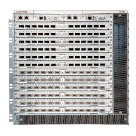
2 Switch Overview 2.1 Front of Chassis Fully loaded FortiSwitch-1000 chassis with dual management cards and a combination of XFP line cards and CX4 line cards. – 8 –... -
Page 9: Back Of Chassis
2.2 Back of Chassis The back of the FortiSwitch-1000 with the full complement of six power supplies installed. Note orientation of fan trays and power supplies. The three power supplies on the left are installed with the release lever side down; the three power supplies on the right are installed with the release lever side up. -
Page 10: Management Card
2.3 Management Card Management Network Port: Ethernet port for out-of-band management of the switch. To configure the switch via the management network port, an IP address must be configured on the port by accessing the switch through the serial port or connecting the switch to a network with a DHCP server. -
Page 11: Line Card (Cx4)
2.4 Line Card (CX4) FS-10G12-CX4 / FS-10G12-CX4-A Line card with CX4 ports; ports can support either powered (active) cables or passive copper cables. “Link up” indicators and link activity indicators are located next to each port. For full description of LED states, see Appendix 1: LED States on page 22. 2.5 Line Card (XFP) FS-10G12-XFP / FS-10G12-XFP-A Line card with XFP optical ports, optical transceivers installed;... -
Page 12: Fan Tray
2.6 Fan Tray FS-1000-FANTRAY Fan tray, showing release tab and handle for use in removing fan tray in case of a fan failure. For full description of LED states, see Appendix 1: LED States on page 22. – 12 –... -
Page 13: Power Supply
2.7 Power Supply FS-1000-PWR850 850 watt power supply unit, showing release tab and handle for use in removing power supply in case of a failure requiring unit replacement (indicated by a solid amber light). For full description of LED states, see Appendix 1: LED States on page 22. To remove power supply unit, press the green release tab toward the center of the unit, then pull on the black handle. -
Page 14: Site Preparation
Rack assembly must be configured to avoid blockage of intake and exhaust registers; a minimum of 6 inches of clearance is required from the front and rear of the FortiSwitch-1000 to ensure adequate air flow through the system. -
Page 15: Feed-Level Redundancy
Each power supply shipped with the FortiSwitch-1000 provides a maximum of 850 W DC power. To calculate the power draw and circuit breaker requirements for the switch as a whole, limit the AC current per power supply to 8A for 100-180VAC and 5A for 200-240VAC. - Page 16 – 16 –...
-
Page 17: Unpacking And Mounting The Switch
4.1.1 Prepare Rack The packing crate in which the FortiSwitch-1000 is shipped is the safest place to store the switch while preparing for installation. Ensure that chassis supports or shelving are properly installed and secured before removing the switch from its crate; if third party or aftermarket shelving is unavailable, Fortinet recommends use of the support brackets included in the shipping crate. -
Page 18: Mounting The Switch
CAUTION: There are sharp metal components inside the chassis; be sure to wear adequate hand protection and grip carefully. A fully-loaded switch weighs over 188 lbs.; Fortinet recommends removing components as needed to reduce weight before lifting and using a minimum of four people to manually lift the switch. -
Page 19: Configuring The Ip Address And Default Gateway
5 Configuring the IP Address and Default Gateway In order to configure or otherwise manage the FortiSwitch-1000 without the use of a console directly attached to the serial console port, an IP address must first be configured on the management card of the switch to allow access via telnet or SSH session. -
Page 20: Dhcp Vs. Static Ip Addressing
5.2.2 DHCP vs. Static IP Addressing The FortiSwitch-1000 is configured to seek an IP address via DHCP by default, but a static IP address can also easily be manually configured on the switch. If the network administrator wishes to always access the switch by a consistent IP address, in switches with dual management cards Fortinet recommends manually configuring the same static management IP address on both cards. -
Page 21: Logging In To The Switch
configuring inband management can be found in the CLI Command Reference Guide under in section 4.2.16 (“mgmt-ip inband”). 5.3.2.1 Logging in to the Switch The switch is factory configured with a single administrator-level login account. To log in to the switch for the first time with administrative privileges: 1. -
Page 22: Appendix 1: Led States
6 Appendix 1: LED States State Meaning State Meaning Notes Mgmt Card In current versions of the FortiSwitch, the ACT light is always off. Future functionality will use this light to indicate state and activity of the external USB card. green This is the active This is the... - Page 23 State Meaning State Meaning Notes (Mgmt Card, cont.) green All thermal yellow One or more sensors within thermal sensors range. out of range. SUMMARY All is well. The Summary lights are mutually (green) SUMMARY light is exclusive; one is on, the other is green if everything off;...
- Page 24 State Meaning State Meaning Notes Power Supply (LED) solid Main output (12V solid Unit has failed green DC) is available amber and must be from this unit. replaced due to fan failure, overtemperature protection (OTP), or standby output overcurrent or undervoltage protection (OCP/UVP).
-
Page 25: Appendix 2: Updating The System Image
<ip_address>:/<file_path>/<file_name> [target_file] where <ip_address>:/<file_path> is the IP address and file path of the local FTP server location of the new image file, <file_name> is the name of the new image and <target_file> is the file name on the FortiSwitch-1000 management card. -
Page 26: Reload System
2. Type system image fabric all <file_name> (where <file_name> is the name of the new fabric card system image) to set the system image for all fabric cards. 3. Type system image line all <file_name> (where <file_name> is the name of the new line card system image) to set the system image for all line cards. -
Page 27: Appendix 3: Regulatory Compliance And Safety Considerations
8 Appendix 3: Regulatory Compliance and Safety Considerations 8.1 Agency Approvals 8.1.1 Safety UL 60950-1 / CSA 22.2 No. 60950-1; Safety of Information Technology Equipment EN / IEC 60950-1; Safety of Information Technology Equipment EN 60825-1 - Safety of Laser Products - Part 1; Equipment Classification. Requirements and User's Guide EN 60825-2;... -
Page 28: Emc Compliance Statements
A minimum of 6 inches of clearance is required from the front and rear of the FortiSwitch-1000 to ensure adequate air flow through system. 8.3.2 Mechanical Mounting of the FortiSwitch-1000 in the rack assembly should be such that a hazardous condition is not achieved due to uneven mechanical loading. – 28 –... -
Page 29: Electrical Rating
Adjustments/settings, maintenance, operational parameters and procedures other than those specified and allowed herein and on the rating plate of the FortiSwitch-1000 may result in increased eye hazard. Do not attempt to perform any repair or maintenance on optical communications components. -
Page 30: Power
Guidelines The following guidelines are designed to help ensure the safety of the people working on or around the FortiSwitch-1000 (such as technicians or installers) and are also designed to protect the routing equipment. Installation of the FortiSwitch-1000 should be performed only by a qualified technician. - Page 31 ESD event damaging the electronics of a system: Make sure the chassis is properly grounded before handling any electronic components (the FortiSwitch-1000 is provided with attachment points on the rear of the chassis for the connection of a grounding cable).
Need help?
Do you have a question about the FortiSwitch-1000 and is the answer not in the manual?
Questions and answers