Table of Contents
Advertisement
Quick Links
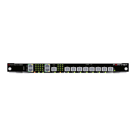
A detailed guide to the FortiSwitch-5003A system. This FortiSwitch-5003A System Guide describes the
FortiSwitch-5003A hardware features, how to install the FortiSwitch-5003A board in a FortiGate-5000 series chassis,
and how to configure the FortiSwitch-5003A system.
The most recent versions of this and all FortiGate-5000 series documents are available from the
the
Fortinet Technical Documentation
Visit
http://support.fortinet.com
FortiSwitch-5003A System Guide
Preliminary-01-30000-77803-20080917
FortiSwitch-5003A
web site (http://docs.forticare.com).
to register your FortiSwitch-5003A system. By registering you can receive product
updates, technical support, and FortiGuard services.
TM
System Guide
FortiGate-5000
page of
Advertisement
Table of Contents

Related Manuals for Fortinet 5003A


Summary of Contents for Fortinet 5003A
- Page 1 System Guide A detailed guide to the FortiSwitch-5003A system. This FortiSwitch-5003A System Guide describes the FortiSwitch-5003A hardware features, how to install the FortiSwitch-5003A board in a FortiGate-5000 series chassis, and how to configure the FortiSwitch-5003A system. The most recent versions of this and all FortiGate-5000 series documents are available from the...
-
Page 2: Warnings And Cautions
ESD protection by wearing an anti-static wrist strap and attaching it to an available ESD connector such as the ESD sockets provided on FortiGate-5000 series chassis. • Make sure all FortiGate-5000 series components have reliable grounding. Fortinet recommends direct connections to the building ground. •... -
Page 3: Table Of Contents
Base and fabric 10-gigabit switching within a chassis ........ 11 Layer-2 link aggregation and redundancy configurations ......12 Hardware installation............13 Setting the FortiSwitch-5003A configuration switch........13 FortiSwitch-5003A mounting components............ 15 Inserting a FortiSwitch-5003A board ............. 16 Removing a FortiSwitch-5003A board ............18 Resetting a FortiSwitch-5003A board ............ - Page 4 Contents FortiSwitch-5003A System Guide 01-30000-77803-20080917...
-
Page 5: Fortiswitch-5003A System
(Gbps) throughput. The FortiGate-5140 chassis is a 14-slot ATCA chassis and the FortiGate-5050 chassis is a 5-slot ATCA chassis. In both chassis the FortiSwitch-5003A board is installed in the first and second hub/switch fabric slots. For most versions of the FortiGate-5140 and 5050 chassis the hub/switch fabric slots are slots 1 and 2. -
Page 6: Front Panel Leds And Connectors
(VLANs, MTSP, trunks, and so on) Front panel LEDs and connectors From the FortiSwitch-5003A font panel you can view the status of the board LEDs to verify that the board is functioning normally. The front panel includes a reset switch for restarting the FortiSwitch-5003A board. -
Page 7: Leds
FortiSwitch-5003A system Front panel LEDs and connectors LEDs Table 1 lists and describes the FortiSwitch-5003A front panel LEDs. Table 1: FortiSwitch-5003A front panel LEDs and switches State Description OOS (Out of Service) Normal operation. Out of service. The LED turns on if the FortiSwitch-5003A board fails. -
Page 8: Base Channel Interfaces
Interface Description Name If the FortiSwitch-5003A board is in the first hub/switch fabric slot, this LED indicates a backplane connection to shelf manager 1. If the FortiSwitch-5003A board is in second hub/switch fabric slot this LED indicates a backplane connection to shelf manager 2. -
Page 9: Fabric Channel Interfaces
* You can configure settings for FortiSwitch-5003A fabric interfaces from the FortiSwitch-5003A CLI. The CLI columns show the names of the interfaces as they appear on the FortiSwitch-5003A CLI. The fabric network activity LEDs show links and network activity for the interfaces... -
Page 10: Front Panel Connectors
Interface or connection activity LED Fabric channel connection between fabric channel 1 and fabric channel 2. This LED is lit if there are two FortiSwitch-5003A boards installed in the chassis to indicate fabric backplane communication between them. 3 to 13 Fabric backplane connection to FortiGate-5000 boards in chassis slots 3 to 13. -
Page 11: Base And Fabric 10-Gigabit Switching Within A Chassis
FortiSwitch-5003A system FortiSwitch-5003A configurations Figure 4: FortiSwitch-5003A base channel 1 HA heartbeat communication Base channel 1 HA Heartbeat Communication POWER 5000SM 5050SAP 5000SM 10/100 10/100 link/Act SERIAL SERIAL link/Act 10/100 10/100 link/Act link/Act Base and fabric 10-gigabit switching within a chassis One FortiGate-RTM-XB2 provides 10-gigabit connections to both FortiGate-5001A fabric channels. -
Page 12: Layer-2 Link Aggregation And Redundancy Configurations
FortiSwitch-5003A board. In this configuration the external switch is connected to FortiSwitch-5003A front panel f5 interface. The switch adds VLAN tags to traffic from the internal and external networks. Figure 6: Basic link aggregation configuration... -
Page 13: Hardware Installation
Troubleshooting Setting the FortiSwitch-5003A configuration switch The SW3 switch on the FortiSwitch-5003A board is factory set by Fortinet with the front panel 14/F8 interface enabled and the fabric backplane slot 14 disabled. This means you can connect the FortiSwitch-5003A front panel 14/F8 interface to a network but you cannot connect a FortiGate-5000 board in slot 14 to the fabric backplane. - Page 14 Front Faceplate If required, change SW3 to the required setting (see Figure 7 Figure Insert the FortiSwitch-5003A board into a chassis and verify that the board starts up and operates correctly. For inserting instructions, see “Inserting a FortiSwitch-5003A board” on page...
-
Page 15: Fortiswitch-5003A Mounting Components
(right handle only) The FortiSwitch-5003A handles align the board in the chassis slot and are used to insert and eject the board from the slot. The right (bottom) handle activates a microswitch that turns on or turns off power to the board. When the right (bottom) handle is open the microswitch is off and the board cannot receive power. -
Page 16: Inserting A Fortiswitch-5003A Board
LEDs remain off. See “Front panel LEDs and connectors” on page It is important to carefully seat the FortiSwitch-5003A board all the way into the chassis, to not use too much force on the handles, and to make sure that the handles are properly locked. - Page 17 Turn both handles to their fully-closed positions. The handles should hook into the sides of the chassis slot. Closing the handles draws the FortiSwitch-5003A board into place in the chassis slot and into full contact with the chassis backplane. The FortiSwitch-5003A front panel should be in contact with the chassis front panel.
-
Page 18: Removing A Fortiswitch-5003A Board
FortiSwitch-5003A board from an ATCA chassis slot. FortiSwitch-5003A boards are hot swappable. The procedure for removing a FortiSwitch-5003A board from a chassis slot is the same whether or not the chassis is powered on. To remove a FortiSwitch-5003A board from a chassis slot Caution: Do not carry the FortiSwitch-5003A board by holding the handles or retention screws. - Page 19 Close Handle Handle Fully Closed and Locked Carefully slide the board completely out of the slot. Re-attach the protective metal frame if you are going ship the FortiSwitch-5003A board or store it outside of a chassis. FortiSwitch-5003A System Guide 01-30000-77803-20080917...
-
Page 20: Resetting A Fortiswitch-5003A Board
All chassis: Firmware problem If the FortiSwitch-5003A board is receiving power and the handles are fully closed, and you have restarted the chassis and the FortiSwitch-5003A still does not start up, the problem could be with FortiOS. Connect to the FortiSwitch-5003A console and try cycling the power to the board. -
Page 21: Quick Configuration Guide
In addition, your FortiSwitch-5003A board should be inserted into the chassis. The FortiSwitch-5003A board should also be powered up and the front panel LEDs should indicate that the boards are functioning normally. -
Page 22: Basic Configuration
Basic configuration Quick Configuration Guide Note: At any time during the configuration process, if you run into problems, you can reset the FortiSwitch-5003A board to the factory defaults and start over. From the CLI enter execute factory-reset. Basic configuration Use the serial cable supplied with your FortiSwitch-5003A board to connect the front panel RJ-45 COM port to the management computer serial port. -
Page 23: Upgrading Fortiswitch-5003A Firmware
Additional configuration You can use the FortiSwitch-5003A CLI to configure other basic system settings such as using config system global to set system time settings and change the system host name. Execute commands are also available for setting the system time and date and backing up the configuration. - Page 24 Additional configuration Quick Configuration Guide If you are using the FortiSwitch-5003A system for link aggregation or just to pass VLANs you need to use the config switch fabric-channel command. This command has 4 keywords: • interface to add VLANs to interfaces and other settings •...
-
Page 25: For More Information
Fortinet Tools and Documentation CD Fortinet documentation is available from the Fortinet Tools and Documentation CD shipped with your Fortinet product. The documents on this CD are current for your product at shipping time. For the latest versions of all Fortinet documentation see the Fortinet Technical Documentation web site at http://docs.forticare.com. - Page 26 © Copyright 2008 Fortinet, Inc. All rights reserved. No part of this publication including text, examples, diagrams or illustrations may be reproduced, transmitted, or translated in any form or by any means, electronic, mechanical, manual, optical or otherwise, for any purpose, without prior written permission of Fortinet, Inc.
Need help?
Do you have a question about the 5003A and is the answer not in the manual?
Questions and answers