Table of Contents
Advertisement
Quick Links
Guided Wave Series
Models:
12-1200IC
12-1799IC
24-1300IC
CONTENTS
Section
Topic
I)
OVERVIEW.......................................................................... 2
II)
IMPORTANT SAFETY CAUTIONS AND WARNINGS.............3
III)
INSTALLATION.................................................................... 3
IV)
V)
INVERTER OPERATION....................................................... 14
VI)
SPECIFICATIONS................................................................ 16
VII)
BATTERY CARE TIPS...........................................................17
VIII)
REFERENCE APPENDIX...................................................... 19
P.O. Box 1306, Newport Beach, CA 92663
Phone: 714-751-0488 Fax: 714-957-1621
E-Mail: sales@newmarpower.com
Inverter/Chargers
INSTALLATION/OPERATION MANUAL
A) Materials Provided............................................... 4
B) Location...............................................................4
C) Mounting............................................................. 4
D) Case Grounding.................................................. 5
E) Battery Selection and Sizing............................... 5
F) Battery (DC) Wiring..............................................6
G) Charging Multiple Battery Banks........................8
H) AC Input Wiring.................................................. 9
I) AC Output Options...............................................10
J) Remote Panel (optional)....................................... 11
A) Charger Operation............................................... 12
B) Output Voltage Adjustment................................ 13
A) Start-Up/Operation............................................. 14
B) Inverter On/OFF Switch Function...................... 15
C) Inverter Shut-down Indicators and Causes........ 15
www.newmarpower.com
G
W
UIDED
AVE
I
/C
NVERTER
HARGER
Page
Phone:+31-35-603-2494 Fax:+31-35-603-2149
E-Mail: newmareuro@newmarpower.com
APR 2002
1
EURO WAREHOUSE
Advertisement
Table of Contents

Related Manuals for NewMar Guided Wave 12-1200IC


Summary of Contents for NewMar Guided Wave 12-1200IC
-
Page 1: Table Of Contents
Inverter/Chargers Guided Wave Series Models: 12-1200IC 12-1799IC 24-1300IC UIDED NVERTER HARGER INSTALLATION/OPERATION MANUAL CONTENTS Section Topic Page OVERVIEW................2 IMPORTANT SAFETY CAUTIONS AND WARNINGS.....3 III) INSTALLATION..............3 A) Materials Provided..........4 B) Location...............4 C) Mounting............. 4 D) Case Grounding..........5 E) Battery Selection and Sizing....... -
Page 2: Overview
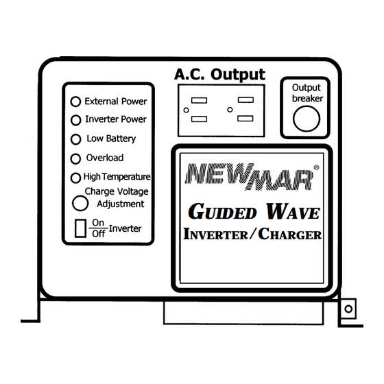
OVERVIEW Your NEWMAR Inverter/Charger uses 12 VDC or 24 VDC (depending on model) battery power to produce 120 VAC, 60 Hz power for operating virtually any AC appliance. It incorpo- rates field-proven technology which provides reliable service in harsh commercial and recre- ational marine applications. -
Page 3: Important Safety Cautions And Warnings
INSTALLATION IMPORTANT: Do not attempt to begin the installation until you have read and understood this section completely. If you have any questions regarding the installation of the inverter/ charger, contact NEWMAR’s technical service before proceeding. U.S.A. HEADQUARTERS EURO WAREHOUSE P.O. -
Page 4: A) Materials Provided
A) Materials Provided The inverter/charger is provided with an installation kit containing the following: (2 ea.) Cable clamps (1 ea.) Warning label for AC distribution panel (1 ea.) Installation/Operation Manual (1 ea.) Customer satisfaction/warranty card If items any are missing, please contact the factory. Upon completion of the installation, please fill out the warranty card and return it to the factory. -
Page 5: D) Case Grounding
D) Case Grounding The case of the inverter/charger must be properly grounded to ship’s ground*. *Per ABYC A-20: A DC chassis grounding conductor shall be connected from the case of the battery charger to the engine negative terminal or its bus, and must not be more than one size under that required for the DC current-carrying conductors. -
Page 6: F) Battery (Dc) Wiring
2) Survey all AC appliances and determine how many watt-hours will be consumed by each during that same period. For instance, if a 100 watt TV will be powered for 3 hours, that equals 300 watt-hours. If a 1,500 watt microwave will also be run for half an hour, then that is another 750 watt-hours (i.e., 1,500 x .5). - Page 7 Wire Size Chart Model Length of Wire from Charger to Batteries (in feet) Over 20' Minimum Wire Gauge (AWG) 12-1200IC Not Recommended 12-1799IC #1/0 Not Recommended 24-1300IC...
-
Page 8: G) Charging Multiple Battery Banks
If desired, the charger may be wired to charge multiple battery banks. This can be accom- plished using NEWMAR’s BI-100 Battery Integrator. The device acts as a “smart” switch, connecting independent battery banks only when a charging voltage is present, then discon- necting them for selective discharge. -
Page 9: H) Ac Input Wiring
H) AC Input Wiring Refer to Figure 3 for all AC input and output wiring options in this section and in section I. Figure 3: AC Input and Outputs GFCI PROTECTED DUPLEX 15 AMP TOTAL OUTPUT AC OUTLETS (MASTER) CIRCUIT BREAKER 3' AC POWER CORD, ATTACHED AT REAR INVERTER ON/OFF SWITCH... -
Page 10: I) Ac Output Options
AC input wiring for the inverter/charger must be routed through a 15 amp fuse or circuit breaker on an AC distribution panel with proper safety/earth chassis ground in accordance with all applicable local codes and ordinances. I) AC Output Options AC output is available from both the front panel AC duplex outlets and via the AC hard- wired output, which is typically routed through an AC distribution panel. -
Page 11: J) Remote Panel (Optional)
Remote monitoring of inverter functions, as well as inverter output activation/shut-off, may be obtained using model ICR-1 Remote Panel, available from NEWMAR. The panel duplicates all of the LED status indicators (discussed in section V following) which are on the front panel and incorporates a secondary on-off switch for the inverter. -
Page 12: Battery Charger Operation And Adjustment
panel plug. (The dummy plug is required to restore proper functioning of the unit if the remote panel must be disconnected for any reason in the future.) To install the in-line plug: 1) Remove the "AC Wiring Compartment" cover (if it has not already been removed to attach AC output wires). -
Page 13: B) Output Voltage Adjustment
Turn counter-clockwise to lower the finishing voltage The factory-set output voltage and approximate user-adjustment range are as follows: Factory Set Model Output Voltage Adjustment Range 12-1200IC 13.8 VDC 12.8 - 14.5 VDC 12-1799IC 13.8 VDC 12.8 - 14.5 VDC 24-1300IC 27.6 VDC... -
Page 14: Inverter Operation
CAUTION: This adjustment should be made only by a qualified marine electrician. Special tools and procedures are required for accurate adjustment of output voltage. Consult with the battery manufacturer for charging voltage recommendations before making this adjust- ment. Over or undercharging will result in battery damage. INVERTER OPERATION A) Start-Up/Operation When all battery and AC wiring has been correctly installed, check for proper operation as... -
Page 15: B) Inverter On/Off Switch Function
1) “Low Input Voltage” L.E.D.: Batteries may be permanently damaged by extreme discharge. Therefore, the inverter monitors battery voltage and shuts off when it reaches a critical low point (10.5 VDC for models 12-1200IC and 12-1799IC; 21.0 VDC for model 24-1300IC). Typically, this occurs when operating the inverter for long periods without any external AC source coming on line to recharge the batteries. -
Page 16: Specifications
Nevertheless, thermal cycling of this sort will shorten the life of the unit, and should not be allowed to continue if it is noted. SPECIFICATIONS MODEL 12-1200IC 12-1799IC 24-1300IC Inverter Output: 115V, 60 Hz. -
Page 17: Vii) Battery Care Tips
Regular maintenance and proper care will assure you reliable service from the most depended upon and sometimes most neglected items, your batteries and battery charger. NEWMAR battery chargers are designed to keep your batteries fully charged but your batteries also need proper regular maintenance to provide a maximum life of service. -
Page 18: Www.newmarpower.com
If your batteries are not the sealed type, distilled water should be added to them whenever needed. The electrolyte should cover the plates by about 1/2", allowing a small air space at the top. Do not fill the cells up to the filler cap as this could cause the battery to sputter out electrolyte when it is being charged. -
Page 19: Reference Appendix
The battery charger has a thermal power reduction circuit to protect the charger from overheating. If you suspect this is the case, refer to the INSTALLATION section for information about proper charger location. 3. ELECTRICAL LEAKAGE. You may have a previously unsuspected source of cur- rent drain from the battery.
Need help?
Do you have a question about the Guided Wave 12-1200IC and is the answer not in the manual?
Questions and answers