Table of Contents
Advertisement
Quick Links
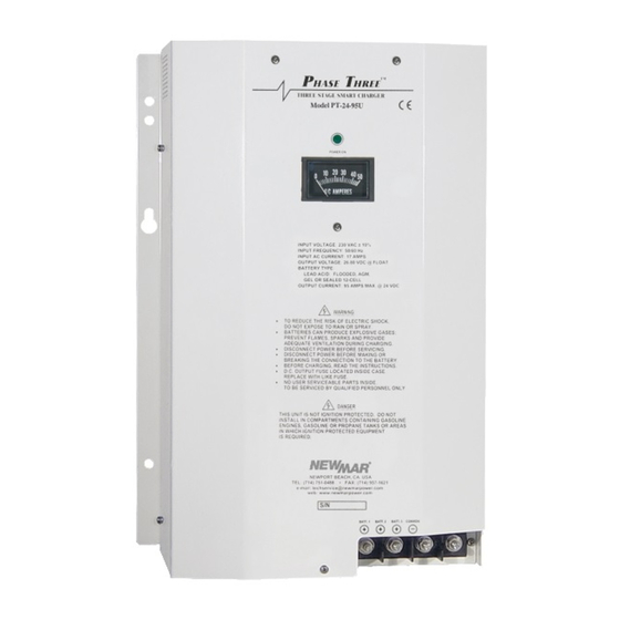
Three Stage Smart Charger
Installation/Operation Manual
Models: PT-24-20U & PT-40U
Section Topic
QUICK REFERENCE GUIDE..................................................................................................... 2
I) GENERAL INFORMATION.................................................................................................. 3
II) IMPORTANT SAFETY INFORMATION........................................................................... 3
III) INSTALLATION..................................................................................................................... 5
A) Materials Provided..................................................................................................... 5
B) Location........................................................................................................................... 5
C) Mounting........................................................................................................................ 5
D) DC Output Wiring........................................................................................................ 5
E) Multiple Unit Parallel Wiring.................................................................................... 6
F) AC Input Wiring............................................................................................................ 7
IV) OPERATION.......................................................................................................................... 7
A) Three Stage Charge Regimen................................................................................ 7
B) Time-Out Circuit........................................................................................................... 8
C) Gel-Cell/Leac-Acid Selector Switch...................................................................... 8
D) Remote Panel Option: 12 Volt Model................................................................... 8
E) Temperature Compensation Option..................................................................... 8
F) Cooling Fan................................................................................................................... 9
G) Output Ammeter......................................................................................................... 9
H) Power-On Indicator..................................................................................................... 9
V) APPLICATION NOTES......................................................................................................... 10
A) Start-Up............................................................................................................................ 10
B) Constant Versus Occastional Use.......................................................................... 10
C) Proper Load Sizing....................................................................................................... 10
D) Operation with Enging.............................................................................................. 10
VI) TROUBLE SHOOTING......................................................................................................... 11
VII) SPECIFICATIONS................................................................................................................ 12
VIII) BATTERY CARE TIPS...................................................................................................... 12
IX) REFERENCE APPENDIX.................................................................................................... 13
X) UNIT DIMENSIONAL DRAWING..................................................................................... 14
Phase Three
Table of Contents
Page
M-PT2420U/40ULF
As of July 2010
Advertisement
Table of Contents


Need help?
Do you have a question about the PT-24-20U and is the answer not in the manual?
Questions and answers