Table of Contents
Advertisement
Quick Links
Topic
Regulation
Output Voltage Adjustment
D.C. Fuses
1
P.O. Box 1306
Newport Beach
California 92663
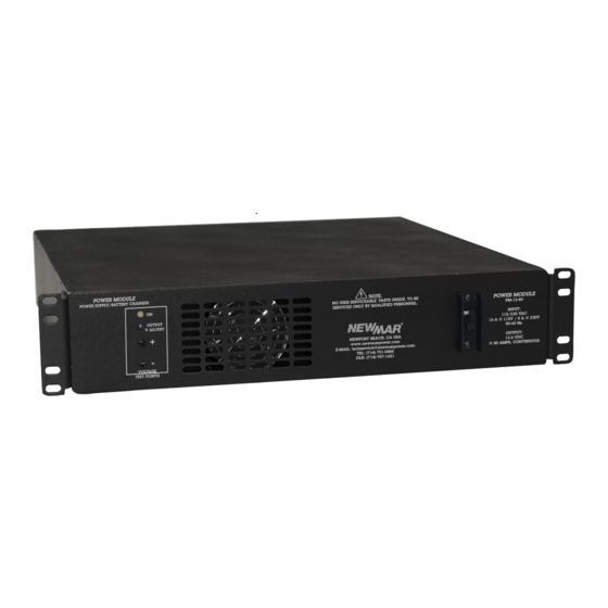
PM Series 1kW Power Module
Power Supply/Battery Charger
PM-12-80, PM-24-40 & PM-48-20
I
nstallatIon
Models:
/o
I
peratIon
nstructIons
Table Of Contents
Page
2
3
3
3
3
3
4
4
4
4
5
6
6
7
7
7
7
7
7
8
8
9
9
M-PM1KW
As Of June 2012
Phone: 714-751-0488
Fax: 714-957-1621
E-Mail: techservice@newmarpower.com
Advertisement
Table of Contents


Need help?
Do you have a question about the PM-12-80 and is the answer not in the manual?
Questions and answers