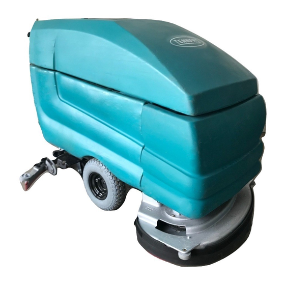
Tennant 5700 Operator's Manual
Electric walk-behind scrubber
Hide thumbs
Also See for 5700:
- Operator's manual (230 pages) ,
- Instruction bulletin (9 pages) ,
- Service manual (362 pages)

Related Manuals for Tennant 5700


Summary of Contents for Tennant 5700
- Page 1 5700 (Electric) (10000000- - Walk- -Behind Scrubber Operator Manual The Safe Scrubbing Alternativer ES Extended Scrub System North America / International 331530 Rev. 02 (10-2008) *331530* www.tennantco.com...
- Page 2 PO Box 1452 Minneapolis, MN 55440 Phone: (800) 553--8033 or (763) 513--2850 www.tennantco.com FaST- -PAK is a US registered and unregistered trademark of Tennant Company. Specifications and parts are subject to change without notice. Copyright E 2006, 2008 TENNANT, Printed in U.S.A.
-
Page 3: Table Of Contents
....STOP SCRUBBING ....5700 331530 (10- -08) - Page 4 ....... MACHINE DIMENSIONS ....5700 331530 (10- -08)
-
Page 5: Safety Precautions
- - Turn off machine and remove key. This machine is designed solely for scrubbing dirt 5. When servicing machine: and dust in an indoor environment. Tennant does - - Avoid moving parts. Do not wear loose not recommend using this machine in any other jackets, shirts, or sleeves when environment. - Page 6 FOR SAFETY LABEL - - LOCATED ON THE ON THE UNDERSIDE OF THE SOLUTION OPERATOR CONSOLE. TANK COVER. 10066 FLAMMABLE SPILLS LABEL - - LOCATED ON THE OPERATOR CONSOLE. BATTERY CHARGING LABEL - - LOCATED ON THE UNDERSIDE OF THE SOLUTION TANK. 5700 331530 (9- -06)
-
Page 7: Operation
Tennant representative. - Order parts and supplies directly from your authorized Tennant representative. Use the parts manual provided when ordering parts. - After operation, follow the recommended daily and hourly procedures stated in the MAINTENANCE CHART. -
Page 8: Machine Components
J. Recovery tank drain hose K. Solution tank hose L. Support arm M. Stop arm N. Batteries O. Scrub head P. Scrub brush access cover Q. Scrub brush idler door R. FaST solution system (option) ec- H2O System Module (option) 5700 331530 (10- -08) -
Page 9: Control Panel Symbols
Circuit breaker #1 Recovery tank full Circuit breaker #2 Scrub brushes down and on Circuit breaker #3 Scrub brushes up and off Circuit breaker #4 Battery charge Circuit breaker #5 Scrub brush pressure Circuit breaker #6 5700 331530 (9- -06) -
Page 10: Controls And Instruments
M. Circuit breakers N. Squeegee lever O. Power kill switch (option) P. Steering height adjustment latch Q. Solution tank hose R. Recovery tank drain hose S. Speed reduction knob (option) T. ec- H2O system indicator light (option) 5700 331530 (10- -08) -
Page 11: Steering Handles
Backward: Rotate the handles toward you. Turning: Push the machine in the direction of the turn with the steering handles. The machine will turn on the swivel casters. Stopping: Release the handles. 5700 331530 (9- -06) -
Page 12: Solution Flow Lever
POWER WAND SWITCH (OPTION) The power wand switch turns on and off the power wand solution system. On: Press the top of the switch. The switch will light up. Off: Press the bottom of the switch. 5700 331530 (10- -08) -
Page 13: Fast Switch (Option)
Drain, raise and refill the solution tank with clear cool water only before operating the ec- -H2O system. Conventional cleaning detergents/ restorers may cause failure to the ec- -H2O solution system. 5700 331530 (10- -08) -
Page 14: Recovery Tank Full Light
NOTE: The reading on the battery discharge indicator is not accurate when the machine is first powered on. Operate the machine a few minutes before reading the charge level of the batteries. 5700 331530 (9- -06) -
Page 15: Brush Pressure Gauge
The scrub brushes down light comes on when the scrub brushes are lowered enough to touch the floor. The light goes off when the scrub brushes are raised off the floor. The light is located in the scrub brush switch. 5700 331530 (9- -06) -
Page 16: Scrub Brushes Switch
MACHINE ON LIGHT The machine on light comes on when the machine is powered on with the on-off key switch. The machine on light goes off when the machine is powered off. 5700 331530 (10- -08) -
Page 17: On-Off Key Switch
SPEED REDUCTION KNOB (OPTION) The speed reduction knob adjusts the machine’s maximum travel speed. To reduce the maximum travel speed, turn the knob to the left. To increase the maximum travel speed, turn the knob to the right. 5700 331530 (9- -06) -
Page 18: Power Kill Switch (Option)
40 A Heavy duty vacuum fan 25 A Machine propel 10 A Machine controls 20 A Scrub brush 35 A Heavy duty disk scrub brush 20 A Scrub brush 35 A Heavy duty disk scrub brush 5700 331530 (3- -08) -
Page 19: Fuses (Option)
The drain hose is plugged by placing the hose plug in the end of the hose and turning the plug latch to tighten the plug. 5700 331530 (10- -08) -
Page 20: Recovery Tank Drain Hose
The arm is released by pulling up on it. STOP ARM The stop arm prevents the solution tank from fully closing when the tank is lowered. Push the arm in to lower the solution tank completely. 5700 331530 (9- -06) -
Page 21: Squeegee Down Pressure Cams
PARKING BRAKE (OPTION) The parking brake is controlled with a foot pedal and a release lever located by the squeegee. Set: Push down on the foot pedal. Release: Pull up on the release lever. 5700 331530 (9- -06) -
Page 22: How The Machine Works
700 mm (28 in) squeegee is used with the 700 model scrub head, as well as the 800 mm (32 in) with the model 800, and the 900 mm (36 in) with the model 900. The two available brush types are disk and cylindrical. 5700 331530 (9- -06) -
Page 23: Fast Scrubbing System (Option)
FaST system. Conventional cleaning detergents/ restorers may cause failure to the FaST solution system. NOTE: Storage or transporting machines equipped with FaST in freezing temperatures requires special procedures. Check with a TENNANT representative for advice. 5700 331530 (3- -08) -
Page 24: Ec--H2O System (Option)
Drain, raise and refill the solution tank with clear cool water only before operating the ec- -H2O system. Conventional cleaning detergents/ restorers may cause failure to the ec- -H2O solution system. 5700 331530 (10- -08) -
Page 25: Pre-Operation Checklist
- FaST or ec- H2O Scrubbing: Check that all conventional cleaning agents/restorers are drained and rinsed from the solution tank. - FaST or ec- H2O Scrubbing: Check that the solution tank is filled with clear cool water only. 5700 331530 (10- -08) -
Page 26: Installing Fast Pak Agent (Option)
Do not add cleaning agents in the solution tank. Conventional cleaning agents/restorers may cause failure to the FaST solution system.. 3. Raise the solution tank and remove the front cover to access the FaST PAK carton. 5700 331530 (9- -06) - Page 27 FaST PAK, simply squeeze and release the hose several times. If the previous FaST PAK was run dry, it may take up to 3 minutes of operation to remove any air pockets in the system before you achieve maximum foaming. 5700 331530 (10- -08)
-
Page 28: Starting The Machine
STARTING THE MACHINE 1 Turn the machine power on. 2 Release the machine parking brake, if your machine has this option. FILLING THE TANKS 1. Start the machine. 2. Drive the machine to the filling site. 5700 331530 (9- -06) - Page 29 5. ES mode: Lift up the solution tank. Fill the recovery tank with water 50 mm (2 in) below the top of the ES filter located on the bottom of the tank, approximately 87 L (23 gal) of water. 5700 331530 (9- -06)
- Page 30 For specific recommendations, contact your Tennant representative. WARNING: Flammable materials can cause an explosion or fire. Do not use flammable materials in tank(s). 5700 331530 (10- -08)
-
Page 31: Normal Scrubbing
Polishing pad -- This white pad is for polishing floors. Maintains a high gloss. Use for buffing very soft finishes and lower traffic areas, or use for polishing soft waxes on wood floors. 5700 331530 (9- -06) - Page 32 1. Start the machine. 2. Drive the machine to the area to be scrubbed. 3. Lower the squeegee to the floor with the squeegee lever. 5700 331530 (9- -06)
- Page 33 H2O module failure may result if operated without water for an extended period. ec- H2O SYSTEM INDICATOR LIGHT CODE CONDITION Solid green Normal operation Blinking red Flush ec- -H2O module Solid red Contact Service Center 5700 331530 (10- -08)
- Page 34 6. Drive the machine forward and scrub as required. WARNING: Flammable materials or reactive metals can cause an explosion or fire. Do not pickup. 7. Adjust brush pressure for cleaning application with the scrub brushes switch, while watching the brush pressure gauge. 5700 331530 (10- -08)
-
Page 35: Double Scrubbing
The FaST and ec- -H2O system flow rates are pre- -set. The ec- -H2O module has optional flow rate settings. If solution flow adjustments are required, contact an Authorized Service Center. FOR SAFETY: When using machine, go slow on inclines and slippery surfaces. 5700 331530 (10- -08) -
Page 36: Stop Scrubbing
OPERATION STOP SCRUBBING 1. Release the steering handles. 2. Raise the scrub brushes with the scrub brushes switch until the scrub brushes down light goes off. 3. Raise the squeegee with the squeegee lever. 5700 331530 (9- -06) -
Page 37: Draining And Cleaning The Tanks
2. Drive the machine next to a floor drain or sink. 3. Turn the machine power off. FOR SAFETY: Before leaving or servicing machine, stop on level surface, and turn off machine. 4. Set the parking brake, if your machine has this option. 5700 331530 (9- -06) - Page 38 8. ES mode: When the solution tank has completely drained, replace the drain hose plug in the solution tank drain hose and place the solution tank drain hose back onto the mounting clip on the machine. 5700 331530 (9- -06)
- Page 39 11. Lift the solution tank to reach the recovery tank. 12. Flush out the inside of the recovery tank with clean water. NOTE: Do not use steam to clean the tank. 5700 331530 (3- -08)
- Page 40 NOTE: Be sure the vacuum filter is dry before reinstalling it in the machine. 16. An optional debris screen is available for the recovery tank entry. If your machine is equipped with this screen, remove and clean it daily. 5700 331530 (3- -08)
- Page 41 18. Pull up on the support arm and lower the solution tank. Push the stop arm in to completely lower the solution tank. 19. Cylindrical scrub head: Remove and clean the debris trough. Place the trough back in the scrub head. 5700 331530 (9- -06)
-
Page 42: Stop The Machine
OPERATION ON INCLINES Drive the machine slowly on inclines. FOR SAFETY: When using machine, go slow on inclines and slippery surfaces. The maximum rated climb and descent incline with empty tanks is 8_, with full tanks is 6_. 5700 331530 (9- -06) -
Page 43: Post-Operation Checklist
- Empty and clean the debris tray. (if applicable). - Check the service records to determine maintenance requirements. - FaST scrubbing: If FaST PAK is empty after scrubbing, install a new FaST PAK or connect supply hose to the storage plug. 5700 331530 (9- -06) -
Page 44: Machine Troubleshooting
Uneven brush pressure, level scrub head Broken brush drive belts on cylindrical scrub head, replace belt Contact Service Center Low battery charge Charge batteries until the charger automatically turns off Tire pressure low Increase tire pressure 5700 331530 (9- -06) - Page 45 H2O Model: Defective light or module Contact Service Center ec- -H2O system indicator light does not turn on ec- H2O Model: Clogged module Contact Service Center No water flow Defective solution pump Replace solution pump 5700 331530 (10- -08)
-
Page 46: Options
Do not pickup. 1. Turn the machine power off. FOR SAFETY: Before leaving or servicing machine, stop on level surface, and turn off machine. 2. Set the parking brake, if your machine has this option. 5700 331530 (9- -06) - Page 47 3. Remove the squeegee suction hose from the top of the squeegee. 4. Put together the wand and the wand hose. 10080 5. Connect the vacuum wand hose and the squeegee suction hose with the adapter. 6. Turn the machine power on. 5700 331530 (9- -06)
- Page 48 OPERATION 7. Lower the squeegee with the squeegee lever to turn the vacuum system on. 8. Vacuum the floor. 06599 9. When finished, raise the squeegee to shut off the vacuum. 10.Turn the machine power off. 5700 331530 (9- -06)
- Page 49 OPERATION 11. Remove the vacuum hose from the squeegee suction hose. 12. Reconnect the squeegee suction hose to the top of the squeegee. 5700 331530 (9- -06)
-
Page 50: Power Wand
FOR SAFETY: Before leaving or servicing machine, stop on level surface, and turn off machine. 2. Set the parking brake, if your machine has this option. 3. Remove the squeegee suction hose from the top of the squeegee. 5700 331530 (9- -06) - Page 51 Push the connector in until it stops. Pull on the hose to make sure it is connected. 6. Attach the other ends of the solution and vacuum hoses to the power wand. 7. Turn the machine power on. 5700 331530 (9- -06)
- Page 52 Scrub the floor with the brush side of the cleaning tool. 11. Vacuum up the solution by turning over the cleaning tool so the squeegee side is down. 06202 5700 331530 (9- -06)
- Page 53 06604 12. When finished, switch the power wand off. 13. When finished, raise the squeegee to shut off the vacuum. 14. Disconnect the solution hose from the machine. 5700 331530 (9- -06)
- Page 54 15. Remove the vacuum hose from the squeegee suction hose. 16. Disconnect the other ends of the solution and vacuum hoses from the power wand. 17.Turn the machine power off. 18. Reconnect the squeegee suction hose to the squeegee. 5700 331530 (9- -06)
-
Page 55: Maintenance
Clean and connect hose to stor- and connector (option) ing plug when not in use Front tires Check air pressure 50 Hours Cylindrical brushes Check taper and rotate front to rear FaST Filter screen Clean (option) 5700 331530 (3- -08) - Page 56 1000 (option) Hours Scrub brush motors Check motor brushes Propelling motor Check motor brushes Transaxle Check lubricant level SPL -- Special lubricant, Lubriplate EMB grease (TENNANT part no. 01433--1) GL -- SAE 90 weight gear lubricant 5700 331530 (3- -08)
-
Page 57: Lubrication
The rear casters each have one grease fitting on the caster swivel. Lubricate the caster with a grease gun containing Lubriplate EMB grease (TENNANT part no. 01433--1) every 100 hours of machine operation. TRANSAXLE Check the transaxle lubricant level every 1000 hours of operation by removing one of the orange filler plugs. - Page 58 27_ C (80_ F), the reading must be temperature corrected. Add or subtract to the specific gravity reading 0.004, 4 points, for each 6_ C (10_ F) above or below 27_C (80_ F). 5700 331530 (9- -06)
-
Page 59: Charging The Batteries
DO NOT OVERFILL. The batteries can overflow during charging due to expansion. NOTE: Make sure the battery caps are in place while charging. FOR SAFETY: When maintaining or servicing machine, avoid contact with battery acid. 5700 331530 (9- -06) -
Page 60: Electric Motors
7. Plug the battery charger into the wall outlet. NOTE: If the red “ABNORMAL CYCLE” lamp lights when the TENNANT charger is plugged into a wall outlet, the charger cannot charge the battery and there is something wrong with the battery. -
Page 61: Scrub Head
5. Pull the strap tight through the buckle, and attach the strap end to the skirt using the hook and loop fastener. 6. Raise the scrub head. 5700 331530 (9- -06) -
Page 62: Replacing The Scrub Head Skirt
6. Pull the strap tight through the buckle, and attach the strap end to the skirt using the hook and loop fastener. 7. Adjust the skirt as stated in ADJUSTING THE SCRUB HEAD SKIRT. 5700 331530 (9- -06) -
Page 63: Cylindrical Brush Scrub Head Skirts
3. Remove the retainer strip and hardware. 4. Replace the old skirt with a new skirt and mount in place with the retainer strip and hardware. 5700 331530 (9- -06) -
Page 64: Removing Or Replacing The Scrub Head
1. Lower the scrub head. 2. Turn the machine power off. FOR SAFETY: Before leaving or servicing machine, stop on level surface, and turn off machine. 3. Remove the machine front cover. 5700 331530 (3- -08) - Page 65 5. Disconnect the wire harness. 6. Disconnect the scrub head from the guide by removing the clevis pin. 7. Disconnect the lift arms from the scrub head by removing the two clevis pins. 5700 331530 (9- -06)
-
Page 66: Leveling The Scrub Head
2. Check the level of the scrub head by measuring the distance from the top of the scrub head, to the floor at all four corners. The scrub head should measure the same on all four corners. 5700 331530 (9- -06) - Page 67 Turn the adjustment screw until the scrub head measures level. Tighten the jam nut. 4. Install the machine front cover. 5. Cylindrical scrub head: Check the brush pattern as described in CHECKING AND ADJUSTING CYLINDRICAL BRUSH PATTERN. 5700 331530 (9- -06)
-
Page 68: Scrub Brushes
2. Turn the machine power off and set the parking brake if your machine has this option. FOR SAFETY: Before leaving or servicing machine, stop on level surface, and turn off machine. 3. Open the access cover on either corner of the scrub head. 5700 331530 (9- -06) - Page 69 9. Lift the scrub brush into the drive plug. 10. Check to make sure the brush is securely mounted on the brush drive hub. 11. Close the scrub head access cover. 12. Repeat for the other brush. 5700 331530 (9- -06)
-
Page 70: Cylindrical Brushes
4. Pull the brush out of the scrub head. 5. With the double row end of the brush towards you, guide the brush onto the drive hub. NOTE: Use the double rows on the idler end of the brush. 5700 331530 (9- -06) -
Page 71: Checking And Adjusting Cylindrical Brush Pattern
A polish mark will remain on the floor. 5. Raise the scrub head and move the machine away from the chalked area. Turn the machine power off. 5700 331530 (9- -06) - Page 72 Pull the idle plug off the brush. B. While holding the flat end of the idler shaft with a wrench, loosen the mounting screw on the outside of the idler door. 5700 331530 (9- -06)
-
Page 73: Solution System
The outside of the tank can be cleaned with vinyl cleaner. Rinse and wipe off the level sensors daily. The level sensors are located inside the recovery tank. 5700 331530 (9- -06) -
Page 74: Solution Tank
If the filters become dirty, the solution flow will be reduced. Check and clean these filters if necessary. NOTE: Do not use steam to clean the tank. 5700 331530 (3- -08) -
Page 75: Fast System (Option)
Remove the injector assembly from clamps. Replace the water and air filter. An 8mm hex wrench required to install new water filter. Water Filter (50 Mesh/Brown) Air Filter (50 Mesh/Brown) 5700 331530 (3- -08) -
Page 76: Fast System Filter Screen
FaST PAK holder. Soak the connector in warm water if detergent buildup is visible. When a FaST PAK carton is not installed, store the supply hose connector on the storing plug to prevent the hose from clogging. 5700 331530 (3- -08) -
Page 77: Ec--H2O System (Option)
The module must run the full 7 minute cycle in order to reset the system indicator light and alarm. Repeat flush procedure if the ec- -H2O module does not reset. If module fails to reset, contact an Authorized Service Center. 5700 331530 (10- -08) -
Page 78: Squeegee
7. Turn the machine power off and set the parking brake if your machine has this option. FOR SAFETY: Before leaving or servicing machine, stop on level surface, and turn off machine. 8. Remove the squeegee suction hose from the squeegee. 5700 331530 (9- -06) -
Page 79: Installing The Squeegee Assembly
1. Turn the machine power on. 2. Lower the squeegee. 3. Drive the machine forward, then turn the machine power off. 4. Look at the deflection of the squeegee blade, over the full length of the squeegee blade. 5700 331530 (9- -06) -
Page 80: Adjusting Squeegee Blade Deflection
Turn the squeegee deflection cams clockwise to increase blade deflection. 6. Drive the machine forward again to check the squeegee blade deflection. 7. Readjust the squeegee blade deflection if necessary. 5700 331530 (9- -06) -
Page 81: Adjusting The Squeegee Guide Rollers
FOR SAFETY: Before leaving or servicing machine, stop on level surface, and turn off machine. 3. Loosen the two retention knobs, one at each end on the squeegee. 5700 331530 (9- -06) -
Page 82: Replacing Or Rotating The Front Squeegee Blade
3. Remove the squeegee from the machine. See REMOVING THE SQUEEGEE ASSEMBLY. 4. Remove the rear squeegee blade and retainer. See REPLACING OR ROTATING THE REAR SQUEEGEE BLADE. 5700 331530 (9- -06) - Page 83 Do not overtighten. 10. Install the squeegee assembly on the squeegee pivot. See INSTALLING THE SQUEEGEE ASSEMBLY. 11. Adjust the squeegee blade leveling and deflection as stated in LEVELING THE SQUEEGEE and ADJUSTING SQUEEGEE BLADE DEFLECTION. 5700 331530 (9- -06)
-
Page 84: Belts And Chains
Check the belt tension and wear every 100 hours of operation. STATIC DRAG CHAIN A static drag chain prevents the buildup of static electricity in the machine. The chain is attached to the transaxle. Make sure the chain is always touching the floor. 5700 331530 (9- -06) -
Page 85: Tires
Only push a disabled machine for a very short distance and do not exceed 3.2 kp/h (2 mph). It is NOT intended to be pushed for a long distance or at a high speed. 5700 331530 (9- -06) -
Page 86: Transporting The Machine
AND is 380 mm (15 in) or less from the ground. 5. Position the machine onto the truck or trailer as far as possible. If the machine starts to veer off the centerline of the truck or trailer, stop and straighten the machine. 5700 331530 (9- -06) - Page 87 FOR SAFETY: When unloading machine off truck or trailer, use winch. Do not push the machine off the truck or trailer unless the loading surface is horizontal AND 380 mm (15 in) or less from the ground. 5700 331530 (9- -06)
-
Page 88: Machine Jacking
If your machine is equipped with the off--aisle wand option, operate the off--aisle wand for a few seconds to protect the pump. Continue with the freeze protection procedure if machine is equipped with the ec- -H2O system. 5700 331530 (10- -08) - Page 89 When the water turns clear, press the module switch again to stop the flush cycle. Dispose the antifreeze in an environmentally safe way according to local waste disposal regulations. The machine is now ready for scrubbing. 5700 331530 (10- -08)
-
Page 90: Specifications
Recovery tank capacity to full sensor 114 L (30 gal) Recovery tank capacity to top of tank 152 L (40 gal) Transaxle 90 weight gear lubricant capacity 1.42 L (1.5 qt) GVWR 690 kg (1520 lb) 5700 331530 (9- -06) -
Page 91: Fast System (Option)
1700 mm (67 in) head Aisle turnaround width with 900 mm (36 in) scrub 1725 mm (67.5 in) head Maximum rated climb and descent angle with empty tanks Maximum rated climb and descent angle with full tanks 5700 331530 (10- -08) -
Page 92: Power Type
Chargers (Smart) Chargers (International) TIRES Location Type Size Pressure Front (2) Pneumatic 4.10/3.5 -- 6 415 to 450 kPa (60 to 65 psi) Front (2) Solid (option) 1.2/3.0--6 Rear, casters (2) Solid, non-marking 5 x 2 in 5700 331530 (9- -06) -
Page 93: Machine Dimensions
950 mm (37.5 in) 1065 mm (42 in) 1155 mm (45.5 in) 1600 mm (63 in) 1625 mm (64 in) 1660 mm (65.25 in) 1690 mm (66.5 in) 1090 mm (43 in) 720 mm (28.25 in) 10189 MACHINE DIMENSIONS 5700 331530 (9- -06)
Need help?
Do you have a question about the 5700 and is the answer not in the manual?
Questions and answers