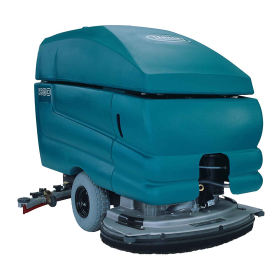
Tennant 5680 Installation Instructions Manual
Drive module replacement kit
Hide thumbs
Also See for 5680:
- Service manual (362 pages) ,
- Operator's manual (79 pages) ,
- Manual (7 pages)
Advertisement
Quick Links
KIT NO. 9011905
Drive Module Replacement Kit
Model: 5680
The original controller board p/n 397785 has been discontinued and replaced by this kit. The kit includes additional
parts for proper installation. Carefully follow the installation instructions as described below.
INSTALLATION INSTRUCTIONS:
Installation Time:
1.5 Hours
Special Tools Required: Ohmmeter to adjust
potentiometer
FOR SAFETY: Before servicing machine, stop
on level surface, turn off machine, and
remove key.
1. Disconnect the black (- ) battery cable from
battery pack.
2. Remove the two screws and the height
adjustment knob from the control console housing.
Lower housing to access control board (Figure 1).
Fig. 1
3. Remove electrical cover from control board.
Discard cover, it's not required with new module
(Figure 2).
Disconnect the wire connections from old board
and remove board from machine (two screws).
Discard old board (Figure 2).
Fig. 2
9011904 Rev. 05 (04- 2018)
9011905 Kit Contents
4
1
5
Ref Part No. Description
1 1212548 Module, Drive [D515113]
2 1206698 Harness, Drive, Adapter [5680]
3 1213069 Harness, Potentiometer
4
392894 Gauge, Discharge, Battery, 36v, w/gasket
5 1073600 Screw, Pan, m4 x 0.7 x 25, fmg
4. Mount the new module to panel. Using a 9/64"
drill bit, drill the top mounting hole location as
described. For the bottom hole, use the module
as a drill template (Figure 3).
Use caution when drilling not to drill into tank.
Drill top
hole
1
2
/
in
8
[54 mm]
Old
board
hole
location
Drill
bottom
hole
Tennant Company
Page 1 of 7
3
8
[209.5 mm]
Attach
module
using
M4x25
Pan
Screw (2)
Fig. 3
www.tennantco.com
2
Qty.
1
1
1
1
2
1
/
in
4
Advertisement

Related Manuals for Tennant 5680


Summary of Contents for Tennant 5680
- Page 1 1 1212548 Module, Drive [D515113] Lower housing to access control board (Figure 1). 2 1206698 Harness, Drive, Adapter [5680] 3 1213069 Harness, Potentiometer 392894 Gauge, Discharge, Battery, 36v, w/gasket 5 1073600 Screw, Pan, m4 x 0.7 x 25, fmg 4.
-
Page 2: Installation Instructions
(6/Blue, 5/Green and 4D/Yellow) and remove the old potentiometer from machine (Figure 6). Remove Potentiometer Potentiometer Wires Potentiometer Screw Star Washers Use second star washer from old potentiometer Fig. 8 Fig. 6 9011904 Rev. 05 (04- 2018) Tennant Company www.tennantco.com... - Page 3 2A/Brown from propel circuit breaker (CB2) and replace it with wire 1C/Red from new harness (figure not shown). Also disable CB1 by removing wires 3A/3C/Orange. CB1 is no longer needed Fig. 10 with new drive module. 9011904 Rev. 05 (04- 2018) Tennant Company www.tennantco.com...
- Page 4 NOTE: For early models, disconnect wire screws. 3B/Orange from key switch and connect wire 33/Orange from new wire harness to key switch (Figure not shown). Connect wire 33/Orange Fig. 17 Fig. 14 9011904 Rev. 05 (04- 2018) Tennant Company www.tennantco.com...
- Page 5 (BDI) and connect the new wire harness as shown (Figure 19). Discard the wire harness that is packaged with the new BDI. It’s not required. From new wire harness Fig. 19 19. Test machine for proper operation. 9011904 Rev. 05 (04- 2018) Tennant Company www.tennantco.com...
- Page 6 Page 6 of 7 KIT NO. 9011905 Drive Module Replacement Kit INSTALLATION INSTRUCTIONS - Continued 1074198_H 9011904 Rev. 05 (04- 2018) Tennant Company www.tennantco.com...
- Page 7 Page 7 of 7 KIT NO. 9011905 Drive Module Replacement Kit INSTALLATION INSTRUCTIONS - Continued 1074198_H 9011904 Rev. 05 (04- 2018) Tennant Company www.tennantco.com...
Need help?
Do you have a question about the 5680 and is the answer not in the manual?
Questions and answers