Moxa Technologies NPort 6000 Series User Manual
Hide thumbs
Also See for NPort 6000 Series:
- User manual (184 pages) ,
- Tech note (5 pages) ,
- Tech note (3 pages)

Related Manuals for Moxa Technologies NPort 6000 Series


Summary of Contents for Moxa Technologies NPort 6000 Series
- Page 1 NPort 6000 Series User’s Manual Sixth Edition, March 2011 www.moxa.com/product © 2011 Moxa Inc. All rights reserved.
-
Page 2: Copyright Notice
Information in this document is subject to change without notice and does not represent a commitment on the part of Moxa. Moxa provides this document as is, without warranty of any kind, either expressed or implied, including, but not limited to, its particular purpose. Moxa reserves the right to make improvements and/or changes to this manual, or to the products and/or the programs described in this manual, at any time. -
Page 3: Table Of Contents
Table of Contents Introduction ............................1-1 Overview ............................1-2 Package Checklist ..........................1-2 NPort 6610/6650 ......................... 1-2 NPort 6150, NPort 6250, and NPort 6450 ..................1-3 Product Features ..........................1-3 Product Selection Chart ........................1-4 Product Specifications ......................... 1-4 NPort 6150 ..........................1-4 NPort 6250/6250-S-SC/6250-M-SC .................... - Page 4 Network Settings ..........................5-6 Basic Network Settings ........................ 5-6 Advanced Network Settings ......................5-9 Configuring the Route Table......................5-10 Module Settings ..........................6-1 NM-TX01, NM-TX02, NM-FX01-M-SC, NM-FX01-S-SC, NM-FX02-M-SC, NM-FX02-S-SC ........ 6-2 Using Ethernet Redundancy ......................6-2 The STP/RSTP Concept ........................ 6-3 Differences between RSTP and STP ....................
- Page 5 Setting up the DDNS and Port Forwarding on NAS .................. C-1 Configuration ............................. C-2 Well Known Port Numbers ........................ D-1 SNMP Agents with MIB II & RS-232 Like Groups ................E-1 RFC1213 MIB-II Supported SNMP Variables ................... E-2 RFC1317 RS-232 Like Groups ....................... E-3 Moxa-NP6000-MIB ..........................E-4...
- Page 6 RADIUS Server ..........................F-1 What is RADIUS? ..........................F-2 Definition ........................... F-2 Client/Server Architecture ......................F-2 Setting up the NPort 6000 ........................F-2 Setting up the RADIUS Server IP Address ..................F-2 Serial Port Configuration ......................F-3 Setting up UNIX Hosts ......................... F-3 Setting up Windows NT Hosts .......................
-
Page 7: Introduction
The NPort 6000 series of secure serial device servers have many exceptional features. There are currently seventeen models in the NPort 6000 series of secure serial device servers. The main differences between the models are the number of ports and the type of network connection employed. All instructions and information presented for the NPort 6000 apply to all models in the series. -
Page 8: Overview
Each NPort 6000 serial device server is shipped in a separate box with a number of standard accessories. In addition, several optional accessories can be ordered separately. When you receive your shipment, please check the contents of the box carefully, and notify your Moxa sales representative if any of the items are missing or appear to be damaged. -
Page 9: Nport 6150, Nport 6250, And Nport 6450
DK-35A DIN-rail mounting kit (35 mm) • DIN-rail power supply Product Features All models in the NPort 6000 series have the following features: • Secure data access modes, including Secure Real COM, Secure TCP Server, Secure TCP Client, and Secure Pair Connection •... -
Page 10: Product Selection Chart
NPort 6000 Series Introduction • Port speeds of up to 921.6 Kbps • Redundant Ethernet Ring capability (STP, RSTP, Turbo Ring, and Turbo Ring 2) • GSM/GPRS or V.92 Modem backup capability • Any Baudrate feature for easy configuration for custom baudrates... -
Page 11: Serial Interface
NPort 6000 Series Introduction Serial Interface Number of Ports: 1 Serial Standards: RS-232/422/485 Connector: DB9 male RS-485 Data Direction Control: ADDC® (Automatic Data Direction Control) Serial Line Protection: 15 KV ESD protection for all signals Console Port: Serial port doubles as RS-232 console port... -
Page 12: Nport 6250/6250-S-Sc/6250-M-Sc
NPort 6000 Series Introduction Standards and Certifications Safety: UL 60950-1, EN 60950-1 EMC: CE, FCC EMI: EN 55022 Class A, FCC Part 15 Subpart B Class A EMS: EN 55024, EN 61000-4-2 (ESD) Level 2/3, EN 61000-4-3 (RS) Level 2,... -
Page 13: Serial Signals
NPort 6000 Series Introduction Serial Communication Parameters Data Bits: 5, 6, 7, 8 Stop Bits: 1, 1.5, 2 Parity: None, Even, Odd, Space, Mark Flow Control: RTS/CTS, DTR/DSR, XON/XOFF Baudrate: 50 bps to 921.6 Kbps (supports non-standard baudrates) Pull High/Low Resistor for RS-485: 1 KΩ, 150 KΩ... -
Page 14: Nport 6450
NPort 6000 Series Introduction Standards and Certifications Safety: UL 60950-1, EN 60950-1 EMC: CE, FCC EMI: EN 55022 Class A, FCC Part 15 Subpart B Class A EMS: EN 55024, EN 61000-4-2 (ESD) Level 2/3, EN 61000-4-3 (RS) Level 2,... - Page 15 NPort 6000 Series Introduction Serial Interface Number of Ports: 4 Serial Standards: RS-232/422/485 Connector: DB9 male RS-485 Data Direction Control: ADDC® (Automatic Data Direction Control) Serial Line Protection: 15 KV ESD protection for all signals Console Port: Serial port 1 doubles as RS-232 console port...
-
Page 16: Nport 6610/6650
NPort 6000 Series Introduction Power Requirements Input Voltage: 12 to 48 VDC Power Consumption: 730 mA @ 12 V, 330 mA @ 24 V Alarm Contact: Relay output with current carrying capacity of 1 A @ 24 VDC Power Line Protection: 1 KV burst (EN61000-4-4: EFT/B), 0.5 KV surge (EN61000-4-5) - Page 17 NPort 6000 Series Introduction Serial Interface Number of Ports: 8, 16, or 32 Serial Standards: NPort 6610: RS-232 NPort 6650: RS-232/422/485 Connector: 8-pin RJ45 RS-485 Data Direction Control: ADDC® (Automatic Data Direction Control) Serial Line Protection: 15 KV ESD protection for all signals...
- Page 18 NPort 6000 Series Introduction Environmental Limits Operating Temperature: Standard Models: 0 to 55°C (32 to 131°F) Wide Temp. Models: -40 to 75°C (-40 to 167°F) Storage Temperature: -40 to 75°C (-40 to 167°F) Ambient Relative Humidity: 5 to 95% (non-condensing)
-
Page 19: Getting Started
Getting Started This chapter covers the hardware installation of the NPort 6000. Software installation is covered in the next chapter. The following topics are covered in this chapter: Panel Layout NPort 6150/6250 NPort 6450 NPort 6610/6650 ... -
Page 20: Panel Layout
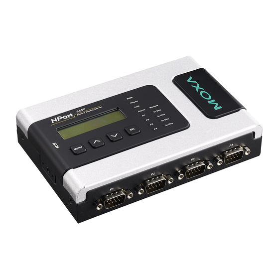
NPort 6000 Series Getting Started Panel Layout NPort 6150/6250 NPort 6150 NPort 6250 NPort 6450... -
Page 21: Nport 6610/6650
NPort 6000 Series Getting Started NPort 6610/6650... -
Page 22: Panel, Din-Rail, And Rack Mounting
NPort 6000 Series Getting Started Panel, DIN-Rail, and Rack Mounting Wall or Cabinet Mounting The NPort 6150, 6250, and 6450 device servers have built-in “ears” for attaching the device server to a wall or the inside of a cabinet. We suggest using two screws per ear to attach the device servers to a wall or the inside of a cabinet. -
Page 23: Connecting The Hardware
NPort 6000 Series Getting Started Connecting the Hardware This section describes how to connect the NPort 6000 to serial devices for the first time. Wiring Requirements ATTENTION Disconnect the power before installing and wiring Disconnect the power cord before installing and/or wiring your NPort 6000. -
Page 24: Connecting To The Network
NPort 6000 Series Getting Started The Shielded Ground (sometimes called Protected Ground) contact is the second contact from the right of the 5-pin power terminal block connector located on the rear panel of the NPort 6600-32/16/8-48V. Connect the SG wire to the Earth ground. -
Page 25: Adjustable Pull High/Low Resistors For The Rs-485 Port
NPort 6000 Series Getting Started LED Name LED Color LED Function Module Green The fiber optic network module is plugged in and has been detected. (6450/6610/6650) The fiber optic network module is not present. Link (on optional Orange Steady on: The NPort 6000 device server is connected to an Ethernet network modules fiber connection, but the port is idle. - Page 26 NPort 6000 Series Getting Started NPort 6150/6250/6450 Jumpers NPort 6150 NPort 6250 NPort 6450...
- Page 27 NPort 6000 Series Getting Started NPort 6650 DIP Switches Pull High Pull Low Terminator 1 KΩ 1 KΩ 120 KΩ 150 KΩ 150 KΩ...
-
Page 28: Initial Ip Address Configuration
Initial IP Address Configuration When setting up the NPort 6000 for the first time, the first thing you should do is configure its IP address. This chapter introduces the different methods that can be used. Refer to Chapter 9, System Management Settings, for more details about network settings. -
Page 29: Static And Dynamic Ip Addresses
NPort 6000 Series Initial IP Address Configuration Static and Dynamic IP Addresses Determine whether your NPort 6000 needs to use a static IP or dynamic IP address (either DHCP or BOOTP/PPPoE application). If your NPort 6000 is used in a static IP environment, you will assign a specific IP address using one •... -
Page 30: Arp
NPort 6000 Series Initial IP Address Configuration ATTENTION If a password has been enabled for the NPort 6000 console and the LCM console is configured for writeable status, the LCM console will require you to enter the password before allowing you access. The password will not be required if the LCM console is configured for read-only access. -
Page 31: Telnet Console
NPort 6000 Series Initial IP Address Configuration 3. Execute the arp -s command from your computer’s MS-DOS prompt as follows: arp -s <IP address> <MAC address> For example, C:\> arp -s 192.168.200.100 00-90-E8-04-00-11 4. Next, execute a special Telnet command by entering the following exactly: telnet 192.168.200.100 6000... - Page 32 NPort 6000 Series Initial IP Address Configuration 4. Press N or use the arrow keys to select Network, and then press ENTER. 5. Press B or use the arrow keys to select Basic, and then press ENTER. 6. Use the arrow keys to move the cursor to IP address. Use the DELETE, BACKSPACE, or SPACE keys to erase the current IP address, and then type in the new IP address and press ENTER.
-
Page 33: Serial Console
NPort 6000 Series Initial IP Address Configuration 11. Press S or use the arrow keys to select System and then press ENTER to restart the NPort 6000. Serial Console The NPort 6000 supports configuration through the serial console, which is the same as the Telnet console but accessed through the RS-232 console port rather than through the network. - Page 34 NPort 6000 Series Initial IP Address Configuration 5. From the Property window’s Terminal page, select ANSI or VT100 for Terminal Type and click OK. 6. If you are using the NPort 6610/6650, you may power it up at this point. If you are using the NPort 6150, 6250, or 6450, hold down the “grave accent key”...
-
Page 35: Introducing Serial Port Operation Modes
Introducing Serial Port Operation Modes In this chapter, we describe the various operation modes of the NPort 6000. NPort 6000 modes are grouped by type of application, such as Device Control or Reverse Terminal. The options include an operation mode that relies on a driver installed on the host computer, and operation modes that rely on TCP/IP socket programming concepts. -
Page 36: Overview
NPort 6000 Series Introducing Serial Port Operation Modes Overview The NPort 6000 network-enables traditional serial (RS-232/422/485) devices. The serial device server is a tiny computer equipped with a CPU and TCP/IP protocols that can bi-directionally translate data between the serial and Ethernet formats. -
Page 37: Real Com And Secure Real Com Modes
NPort 6000 Series Introducing Serial Port Operation Modes Real COM and Secure Real COM Modes The NPort 6000 comes bundled with Real COM drivers for Windows systems and TTY drivers for Linux systems. Real COM mode includes optional data encryption using SSL. -
Page 38: Rfc2217 Mode
Dynamic IP address application Reserve Real COM mode is an innovative operation mode developed by Moxa. It allows NPort 6000 terminal servers to achieve the same effect as Real COM mode, but without needint to apply for a public IP address. In other words, Reverse Real COM mode chan be used even if the NPort is using a private IP address, or is being used in a dynamic IP address environment. -
Page 39: Tcp Client And Secure Tcp Client Modes
NPort 6000 Series Introducing Serial Port Operation Modes TCP Client and Secure TCP Client Modes In TCP Client mode, the NPort 6000 can actively establish a TCP connection to a pre-defined host computer when serial data arrives. After the data has been transferred, the NPort 6000 can automatically disconnect from the host computer by using the Inactivity time settings. -
Page 40: Pair Connection And Secure Pair Connection Modes
NPort 6000 Series Introducing Serial Port Operation Modes Pair Connection and Secure Pair Connection Modes In Pair Connection mode, two NPort 6000 servers work together to remove the 15-meter distance limitation imposed by the RS-232 interface. One server is arbitrarily designated the “master” and the other as the “slave”—it does not matter which is which as long as there is one of each. -
Page 41: Terminal Applications
NPort 6000 Series Introducing Serial Port Operation Modes Terminal Applications Terminal applications involve connecting terminals to UNIX or Windows servers over a network. A terminal connects to the appropriately configured serial port the NPort 6000, and the NPort 6000 transmits information to and from a UNIX or Windows server over the network through its Ethernet port. -
Page 42: Reverse Terminal Applications
NPort 6000 Series Introducing Serial Port Operation Modes Reverse Terminal Applications Reverse terminal applications are similar to terminal applications in that they involve using the NPort 6000 to manage the connection between a terminal and a server. The difference is that with reverse terminal applications, the terminal is connected through the network and the server is connected through the serial port, rather than the other way around. -
Page 43: Printer Modes
NPort 6000 Series Introducing Serial Port Operation Modes Printer Modes The NPort 6000’s Printer mode provides an excellent solution for banking and stock exchange services with huge printing demands. Printer modes involve a network printer that is connected to a serial port on the NPort 6000, with a port number assigned to specify the printer’s location. -
Page 44: Disabled Mode
NPort 6000 Series Introducing Serial Port Operation Modes The NPort 6000 provides dial-in/dial-out access for ISPs and enterprises that need a remote access solution. When a user at a remote site uses a PPP dial-up connection to access the NPort 6000, the NPort 6000 plays the role of a dial-up server, but also ensures that the user has legal access to the network by verifying the user’s... -
Page 45: Configuration With The Web Console
Configuration with the Web Console The web console is the most user-friendly method available to configure the NPort 6000. With a standard web browser, you have easy and intuitive access to all settings and options. In this chapter, we introduce the web console and go through the basic configuration options. -
Page 46: Using Your Web Browser
NPort 6000 Series Configuration with the Web Console Using Your Web Browser Browser Cookie Settings Verify that cookies are enabled for your browser. If the cookies are disabled, you will not be able to use the web console. (Cookies are only used for password transmission.) 1. -
Page 47: Trusted Site Settings
NPort 6000 Series Configuration with the Web Console Trusted Site Settings For Windows 2003 users, you may need to add the NPort 6000’s IP address to your browser’s list of trusted sites. 1. If you see the following window while attempting to view the web console, click on Add… to modify the list... -
Page 48: Opening The Web Console
NPort 6000 Series Configuration with the Web Console Opening the Web Console Open your web browser and enter 192.168.127.254 in the website address line. This is the default IP address for the NPort 6000–if a new address has been assigned, enter the new address instead. Press ENTER to load the page. -
Page 49: Web Console Navigation
NPort 6000 Series Configuration with the Web Console Web Console Navigation On the NPort 6000 web console, the left panel is the navigation panel and contains an expandable menu tree for navigating among the various settings and categories. When you click on a menu item in the navigation panel, the main window will display the corresponding options for that item. -
Page 50: Network Settings
The NPort 6000’s real time clock is powered by a lithium battery. We strongly recommend that you do not attempt replacement of the lithium battery without help from a qualified Moxa support engineer. If you need to change the battery, please contact the Moxa RMA service team. - Page 51 When the user wants to visit a particular website, the user’s computer sends the domain name (e.g., www.moxa.com) to a DNS server to request that website’s numerical IP address. When the IP address is received from the DNS server, the user’s computer uses that information to connect to the website’s web...
-
Page 52: Ipv6 Gateway
NPort 6000 Series Configuration with the Web Console The NPort 6000 will play the role of a DNS client, in the sense that it will actively query the DNS server for the IP address associated with a particular domain name. The following functions on the NPort 6000 web console... -
Page 53: Advanced Network Settings
NPort 6000 Series Configuration with the Web Console gateway computer in order to communicate with the hosts outside the local network environment. For correct gateway IPv6 address information, consult the network administrator. IPv6 DNS server 1: This is an optional field. The IP address of another DNS server may be entered in this field for when DNS server 1 is unavailable. -
Page 54: Configuring The Route Table
NPort 6000 Series Configuration with the Web Console RIP 2 is an extension of RIP. Its purpose is to expand the amount of useful information contained in RIP packets, and to add security elements. RIP 2 has become the standard version of RIP, and the original RIP is no longer used. - Page 55 NPort 6000 Series Configuration with the Web Console Configuring Routes to the Internet In this example, the Notebook PC dials into the NPort 6000 to request a connection to the Internet host at 210.48.96.9, which is not on the local network 203.67.6.xxx. This causes the NPort 6000 to act as a router and send the datagram to the default next-hop router, 203.67.6.254.
- Page 56 NPort 6000 Series Configuration with the Web Console Configuring Routes to the Intranet In this example, dial-in users can make requests to Intranet hosts 202.65.66.4 or 202.65.66.5, which are on network 202.65.66.xxx (located outside network 203.67.6.xxx). You will need to add a route entry for the next-hop router, 203.67.6.252 that delivers requests to network 202.65.66.xxx.
- Page 57 NPort 6000 Series Configuration with the Web Console Configuring Multiple-point Routes For multi-location enterprises, NPort 6000 servers can be placed in different branch offices and used as both multi-point routers and as remote access servers. When hosts (e.g., the Web/FTP and E-mail/News servers shown in the figure) send requests to hosts on another network, such as 202.6.6.xxx or 201.2.2.xxx, the...
-
Page 58: Module Settings
Module Settings In this chapter, we describe additional settings related to the NM-TX01, NM-FX01-M-SC, NM-FX01-S-SC, NM-FX02-M-SC, NM-FX02-S-SC, and NM-GPRS/GSM modules. The same configuration options are also available from the Telnet and serial consoles. The following topics are covered in this chapter: ... -
Page 59: Nm-Tx01, Nm-Tx02, Nm-Fx01-M-Sc, Nm-Fx01-S-Sc, Nm-Fx02-M-Sc, Nm-Fx02-S-Sc
Up to 30 sec Up to 5 sec Moxa developed the proprietary Turbo Ring protocol to optimize communication redundancy and achieve a faster recovery time on the network. The protocol is implemented on both the Ethernet and the serial device server. -
Page 60: The Stp/Rstp Concept
Networks that have a complicated architecture are prone to broadcast storms caused by unintended loops on the network. The Moxa NPort 6000’s STP feature is disabled by default. To be completely effective, you must enable RSTP/STP on every NPort 6000 connected to your network. - Page 61 Root Bridge, for the STP system—bridges with a lower Bridge Identifier are more likely to be designated as the Root Bridge. The Bridge Identifier is calculated using the MAC address of the bridge and a priority defined for the bridge. The default priority of the NPort 6000 series is 32768.
-
Page 62: Differences Between Rstp And Stp
NPort 6000 Series Module Settings • Each port has a cost that specifies the efficiency of each link. The efficiency cost is usually determined by the bandwidth of the link, with less efficient links assigned a higher cost. STP Calculation The first step of the STP process is to perform calculations. -
Page 63: Stp Example
NPort 6000 Series Module Settings STP Example The LAN shown below has three segments, with adjacent segments connected using two possible links. The various STP factors, such as Cost, Root Port, Designated Bridge Port, and Blocked Port are shown in the figure. - Page 64 NPort 6000 Series Module Settings Configuring RSTP Bridge priority Setting Description Factory Default Numerical value Increase this device’s bridge priority by selecting a lower 32768 selected by user number. A device with a higher bridge priority has a greater chance of being established as the root of the Spanning Tree topology.
-
Page 65: Configuring Turbo Ring
Configuring Turbo Ring The Turbo Ring Concept Moxa developed the proprietary Turbo Ring protocol to optimize communication redundancy and achieve a faster recovery time on the network. The Turbo Ring and Turbo Ring V2 protocols identify one NPort 6000 as the master of the network, and then automatically block packets from traveling through any of the network’s... - Page 66 NPort 6000 Series Module Settings The user does not need to configure any of the NPort 6000 units as the master to use Turbo Ring or Turbo Ring V2. If none of the NPort 6000 in the ring is configured as the master, then the protocol will automatically assign master status to one of the NPort 6000 units.
-
Page 67: Configuring Turbo Ring 2
NPort 6000 Series Module Settings Redundant Ports Setting Description Factory Default 1st Redundant Port Select any LAN port of the NPort 6000 to be one of the Port 1 redundant ports. 2nd Redundant Port Select any LAN port of the NPort 6000 to be one of the Port 2 redundant ports. -
Page 68: Gsm Operation Mode
NPort 6000 Series Module Settings industrial cellular modem such as the NM-GPRS/GSM module makes it relatively easy to prepare the product for shipment to different parts of the world. The GSM/GPRS band of NM-GPRS/GSM module is configured to 900/1800 MHz by default. -
Page 69: Gprs Operation Mode
NPort 6000 Series Module Settings Dial-out number: Use this field to configure the number that the user uses to dial out. Dial-in number: Use this field to configure the number that the user uses only to dial in. Initial string: Use this field to configure the initial string that the modem will use to establish the connection. -
Page 70: Sms Operation Mode
NPort 6000 Series Module Settings Connection control Connect Rule Disconnect Rule GPRS Always on/None Always on after power on None Trunk Periodically connect/ Periodically connect (based on the Inactivity time is up Trunk inactivity time connection interval setting) to GPRS after powering on. -
Page 71: Serial Event Settings
NPort 6000 Series Module Settings Event Settings On the Event Settings page, you may configure how administrators are notified of certain system, network, and configuration events. Depending on the event, different options for automatic notification are available, as shown above. Mail refers to sending an e-mail to a specified address. Trap refers to sending an SNMP Trap. -
Page 72: Nm-Modem
NPort 6000 Series Module Settings On the Serial Event Settings page, you may configure how administrators are notified of each serial port’s DCD and DSR changes. Mail refers to sending an e-mail to a specified address. Trap refers to sending an SNMP Trap. - Page 73 NPort 6000 Series Module Settings PPP mode: PPP provides standard PPP service for both dial-in and dial-out. PPPD mode: PPPD (PPP on demand) is used for dial-in services, since it provides PPP services only when receiving a request from a remote PC.
-
Page 74: Connection Control
NPort 6000 Series Module Settings Connection control Connection control Connect Rule Disconnect Rule Modem Always on/None Always on after power on None Trunk Periodically Periodically re-connect (based on the Inactivity time is up Trunk connect/inactivity time connection interval setting) to Modem after power on. -
Page 75: Configuring Serial Port Operation Modes
Configuring Serial Port Operation Modes In this chapter, we explain how to configure the individual serial port modes. The following topics are covered in this chapter: Port Setting Basics Device Control Applications Real COM Mode Reverse Real COM Mode ... -
Page 76: Port Setting Basics
NPort 6000 Series Configuring Serial Port Operation Modes Port Setting Basics Each serial port on the NPort 6000 can be configured independently. To configure the operation mode and settings for a port, expand Serial Port Settings in the navigation panel, then expand the port that you would like to configure. - Page 77 NPort 6000 Series Configuring Serial Port Operation Modes periodic “keep alive” packets. If the remote host does not respond to the packet within the time specified in this field, the NPort 6000 will force the existing TCP connection to close. For socket and device control modes, the NPort 6000 will listen for another TCP connection from another host after closing the connection.
- Page 78 NPort 6000 Series Configuring Serial Port Operation Modes Command by command operation (default =Disable): Command by command mode can only support one request and one response from each host. When the NPort 6000 receives a command from any host on the Ethernet, the NPort 6000 will store the command in the buffer.
-
Page 79: Reverse Real Com Mode
NPort 6000 Series Configuring Serial Port Operation Modes • Delimiter + 1: Data in the buffer will be transmitted after 1 additional byte is received following the delimiter. • Delimiter + 2: Data in the buffer will be transmitted after 2 additional bytes are received following the delimiter. - Page 80 NPort 6000 Series Configuring Serial Port Operation Modes ATTENTION If an NPort 6000 serial port is in Reverse Real COM mode and configured for SSL encryption, make sure the Reverse Real COM driver is configured the same way. This is done through the NPort Windows Driver Manager, which is installed with the driver.
-
Page 81: Rfc2217 Mode
NPort 6000 Series Configuring Serial Port Operation Modes • Delimiter + 2: Data in the buffer will be transmitted after 2 additional bytes are received following the delimiter. • Strip Delimiter: Data in the buffer is first stripped of the delimiter before being transmitted. -
Page 82: Socket Applications
NPort 6000 Series Configuring Serial Port Operation Modes TCP port (default=4001): This is the TCP port number assignment for the serial port on the NPort 6000. It is the port number that the serial port uses to listen to connections, and that other devices must use to contact the serial port. - Page 83 NPort 6000 Series Configuring Serial Port Operation Modes TCP alive check time (default=7 min): This field specifies how long the NPort 6000 will wait for a response to “keep alive” packets before closing the TCP connection. The NPort 6000 checks connection status by sending periodic “keep alive”...
- Page 84 NPort 6000 Series Configuring Serial Port Operation Modes Command by command operation (default=Disable): Command by command mode can only support one request and one response from each of the different hosts. When the NPort 6000 receives a command from any host on the Ethernet,...
-
Page 85: Tcp Client Mode
NPort 6000 Series Configuring Serial Port Operation Modes • Delimiter + 1: Data in the buffer will be transmitted after 1 additional byte is received following the delimiter. • Delimiter + 2: Data in the buffer will be transmitted after 2 additional bytes are received following the delimiter. - Page 86 NPort 6000 Series Configuring Serial Port Operation Modes ATTENTION Inactivity time is ONLY active when Connection Control (see below) is set to Any character/Inactivity time. Ignore jammed IP (default=Disable): This option determines how the port will proceed if multiple hosts are connected and one or more of the hosts stops responding as the port is transmitting data.
-
Page 87: Udp Mode
NPort 6000 Series Configuring Serial Port Operation Modes length between 1 and 1024 bytes is specified, data in the buffer will be sent as soon it reaches the specified length. Delimiter 1 and Delimiter 2 (default=None): When Delimiter 1 is enabled, the serial port will clear the buffer and send the data to the Ethernet port when a specific character, entered in hex format, is received. -
Page 88: Pair Connection Mode
NPort 6000 Series Configuring Serial Port Operation Modes ATTENTION The maximum selectable IP address range is 64 addresses. However, when using multi-unicast, you may enter IP addresses of the form xxx.xxx.xxx.255 in the Begin field. For example, enter 192.127.168.255 to allow the NPort 6000 to broadcast UDP packets to all hosts with IP addresses between 192.127.168.1 and... -
Page 89: Pair Connection Slave Mode
NPort 6000 Series Configuring Serial Port Operation Modes In effect, the serial port that is in Pair Connection Master mode will be acting as a TCP client and the one that is slave mode will be acting as a TCP server. In practice, it does not matter which port is the master and which port is the slave. -
Page 90: Ethernet Modem Mode
NPort 6000 Series Configuring Serial Port Operation Modes NPort 6000 will listen for another TCP connection from another host after closing the connection. If TCP alive check time is set to 0, the TCP connection will remain open even if there is no response to the “keep alive”... -
Page 91: Disconnection Request From Remote Site
NPort 6000 Series Configuring Serial Port Operation Modes ATS0≧1: The NPort 6000 will accept the TCP connection immediately and then send the “CONNECT baud” command to the serial port, in which baud represents the baudrate of the NPort 6000’s serial port. After that, the NPort 6000 immediately enters data mode. - Page 92 NPort 6000 Series Configuring Serial Port Operation Modes Result code type ATV0 for digit code, ATV1 for text code (default) 0=OK 1=connect 2=ring 3=No carrier 4=error Reset (disconnect, enter command mode and restore the flash settings) AT&C Serial port DCD control AT&C0=DCD always on...
-
Page 93: Terminal Applications
NPort 6000 Series Configuring Serial Port Operation Modes Terminal Applications Terminal ASCII (TERM_ASC) Authentication type (default=None): This field allows you to configure the method used, if any, to verify a user’s ID and authorization. Option Description Local Verify the ID against the NPort 6000 User Table. -
Page 94: Terminal Bin (Term_Bin)
NPort 6000 Series Configuring Serial Port Operation Modes Primary and Secondary host address: If specified, the fields designate permanent hosts to which the terminal will always be connected. Telnet TCP port (default=23): By default, the Telnet TCP port number is set to 23, which is the default TCP port number for Telnet. - Page 95 NPort 6000 Series Configuring Serial Port Operation Modes Inactivity time (default=0 min): This field specifies how long the NPort 6000 will wait for incoming and outgoing data through the serial port before closing the TCP connection. The TCP connection is closed if there is no incoming or outgoing data through the serial port for the specified Inactivity time.
-
Page 96: Ssh
NPort 6000 Series Configuring Serial Port Operation Modes TCP alive check time (default=7 min): The TCP connection will be closed if there is no TCP activity for the specified amount of time. If this is set to 0, the TCP connection will remain open even if the connection remains idle. -
Page 97: Reverse Terminal Applications
NPort 6000 Series Configuring Serial Port Operation Modes Try next type on authentication denied (default=Disable): The field enables or disables the system to try next type on first authentication denied. Login user name: Enter the terminal login ID here. Login password: Enter the password for the terminal login here. -
Page 98: Reverse Ssh Mode
NPort 6000 Series Configuring Serial Port Operation Modes Try next type on authentication denied (default=Disable): The field enables or disables the system to try next type on first authentication denied. Map keys <CR-LF> (default=CR-LF): This specifies how the ENTER key is mapped from the Ethernet port through the serial port. -
Page 99: Printer Applications
NPort 6000 Series Configuring Serial Port Operation Modes RADIUS - Local Radius authentication is tried first, switching to Local if unsuccessful. Local - RADIUS Authentication is performed locally first, switching to Radius if unsuccessful. TACACS+ Verify the ID against the external TACACS+ server. -
Page 100: Lpd Prn Mode
NPort 6000 Series Configuring Serial Port Operation Modes LPD PRN Mode TCP alive check time (default=7 min): This field specifies how long the NPort 6000 will wait for a response to “keep alive” packets before closing the TCP connection. The NPort 6000 checks connection status by sending periodic “keep alive”... -
Page 101: Pppd Mode
NPort 6000 Series Configuring Serial Port Operation Modes PPP provides standard PPP service for both dial-in and dial-out. Destination IP address: This is the IP address of the remote dial-in/ dial-out server. Source IP address: The Source IP address is IP address assigned to this serial port. -
Page 102: Slip Mode
NPort 6000 Series Configuring Serial Port Operation Modes PPPD (PPP on demand) is used for dial-in services, since it provides PPP services only when receiving a request from a remote PC. Destination IP address: This is the IP address of the remote dial-in/ dial-out server. -
Page 103: Slipd Mode
NPort 6000 Series Configuring Serial Port Operation Modes SLIP provides standard SLIP service for both dial-in and dial-out. Destination IP address: This is the IP address of the remote dial-in/ dial-out server. Source IP address: The Source IP address is IP address assigned to this serial port. -
Page 104: Dynamic Mode
NPort 6000 Series Configuring Serial Port Operation Modes Dynamic Mode Dynamic mode integrates PPPD, SLIPD, and Terminal dial-in services. Dynamic mode automatically detects which remote connection mode is being used, and provides corresponding services. You can individually enable/disable PPP/SLIP/Terminal services by selecting Yes or No next to the corresponding option. Yes will enable that type of service;... -
Page 105: Additional Serial Port Settings
Additional Serial Port Settings In this chapter, we describe additional serial port settings on the NPort 6000. The same configuration options are also available through the telnet and serial console. The following topics are covered in this chapter: Port Communication Parameters ... -
Page 106: Port Communication Parameters
NPort 6000 Series Additional Serial Port Settings Port Communication Parameters Port alias: This optional field allows you to assign an alias to a port for easier identification. Serial Parameters ATTENTION The serial parameters for the each serial port on the NPort 6000 should match the parameters used by the connected serial device. -
Page 107: Port Data Buffering/Log
NPort 6000 Series Additional Serial Port Settings Port Data Buffering/Log The NPort 6000 supports port buffering to prevent the loss of serial data when the Ethernet connection is down. Port buffering can be used in TCP Server mode, TCP Client mode, and Pair Connection mode. For other modes, the port buffering settings will have no effect. -
Page 108: Port Cipher Settings
NPort 6000 Series Additional Serial Port Settings Port Cipher Settings Serial Port Settings Port N Cipher Settings Used to choose cipher priority for SSL and SSH to build secure connections. The Secure Mode(SSL) Ciphers are for when Secure mode is be selected. The SSH/Reverse SSH Ciphers are only for SSH terminals and Reverse SSH terminals. -
Page 109: System Management Settings
System Management Settings In this chapter, we describe additional server settings on the NPort 6000. The same configuration options are also available through the telnet and serial console. The following topics are covered in this chapter: Misc. Network Settings ... -
Page 110: Misc. Network Settings
NPort 6000 Series System Management Settings Misc. Network Settings Accessible IP List The NPort 6000 uses an IP address-based filtering method to control access to its serial ports. The Accessible IP list allows you restrict network access to the NPort 6000. Access is controlled by IP address. -
Page 111: Snmp Agent Settings
NPort 6000 Series System Management Settings SNMP Agent Settings SNMP: To enable the SNMP Agent function, select the Enable option, and enter a community name (e.g., public). Read community string (default=public): This is a text password mechanism that is used to weakly authenticate queries to agents of managed network devices. -
Page 112: Ddns
NPort 6000 Series System Management Settings DDNS Please refer to Appendix C, Dynamic Domain Name Server, for information on setting up DDNS on your NPort 6000 Host Table The Host Table may be used to simplify IP address entry on the NPort 6000 console by assigning a Host Name to a Host IP Address. -
Page 113: Authentication Server
NPort 6000 Series System Management Settings The NPort 6000 User Table may be used for to authenticate users for terminal or reverse terminal access and is useful if you do not have an external RADIUS server for authentication. The NPort 6000 User Table stores up to 64 entries, with fields for User Name, Password, and Phone Number. -
Page 114: Configure The Remote Log Server
NPort 6000 Series System Management Settings System System Cold Start NPort 6000 cold start. System Warm Start NPort 6000 warm start. Network DHCP/BOOTP/PPPoE Get IP of the NPort 6000 is refreshed. IP/Renew Time synchronization successful. NTP Connect Fail The NPot 6000 failed to connect to the NTP Server. -
Page 115: Auto Warning Settings
NPort 6000 Series System Management Settings Auto Warning Settings Event Settings On the Event Settings page, you may configure how administrators are notified of certain system, network, and configuration events. Depending on the event, different options for automatic notification are available, as shown above. -
Page 116: Serial Event Settings
NPort 6000 Series System Management Settings Serial Event Settings On the Serial Event Settings page, you may configure how administrators are notified of each serial port’s DCD and DSR changes. Mail refers to sending an e-mail to a specified address. Trap refers to sending an SNMP Trap. -
Page 117: E-Mail Alert
NPort 6000 Series System Management Settings E-mail Alert The E-mail Alert settings configure how e-mail warnings are sent for system and serial port events. You may configure up to 4 e-mail addresses to receive automatic warnings. ATTENTION Consult your Network Administrator or ISP for the proper mail server settings. The Auto warning function may not work properly if it is not configured correctly. -
Page 118: Snmp Trap
NPort 6000 Series System Management Settings SNMP Trap SNMP trap server IP: Use this field to indicate the IP address to use for receiving SNMP traps. Trap version (default=v1): Use this field to select the SNMP trap version. Trap community (default=public): Use this field to designate the SNMP trap community. -
Page 119: Ping
Please refer to Save Configuration later in this chapter for more information. Any unsaved changes will be discarded when the firmware is upgraded. To upgrade the firmware, simply enter the file name and click Submit. The latest firmware can be downloaded at www.moxa.com. Configuration Import/Export The NPort 6000 can share or back up its configuration by exporting all settings to a file, which can then be imported into another NPort 6000. -
Page 120: Load Factory Defaults
NPort 6000 Series System Management Settings To import a configuration, go to System Management Maintenance Configuration Import. Enter the configuration file path/name and click Submit. The NPort 6000’s configuration settings will be updated according to the configuration file. If you also wish to import the IP configuration (i.e., the NPort 6000’s IP address, netmask, gateway, etc.), make sure that Import all configurations including IP configurations... -
Page 121: Change Password
NPort 6000 Series System Management Settings This function will reset all of NPort 6000’s settings to the factory default values. All previous settings including the console password will be lost. If you wish to keep the NPort 6000 IP address, netmask, and other IP settings, make sure Keep IP settings is checked off before loading the factory defaults. -
Page 122: Certificate/Key Delete
NPort 6000 Series System Management Settings Certificate/Key Delete System Monitoring Serial to Network Connections Go to Serial to Network Connections under Serial Status to view the operation mode and status of each connection, for each serial port. All monitor functions will refresh automatically every 5 seconds. -
Page 123: Serial Port Status
NPort 6000 Series System Management Settings Serial Port Status Go to Serial Port Status under Serial Status to view the current status of each serial port. Serial Port Status Buffering. Monitor port buffering usage (bytes) of each serial port. -
Page 124: Serial Port Settings
NPort 6000 Series System Management Settings Serial Port Settings Go to Serial Port Settings under Serial Status to view a summary of the settings for each serial port. Serial Cipher Usage Status Serial Status → Cipher Usage Status Monitor cipher usage and connection status of each serial port. It is depend on Cipher Settings. -
Page 125: Network Connections
NPort 6000 Series System Management Settings Network Connections Go to Network Connections under System Status to view network connection information. Network Statistics Go to Network Statistics under System Status to view network statistics. Ethernet statistics Sent: Total number of output datagram packets delivered to the Ethernet. -
Page 126: Network Module
NPort 6000 Series System Management Settings PPP statistics Received: Received IP datagram packets. RDiscard: Received but discarded IP datagram packets. ErrSum: Checksum error packets. Sent: Sent IP datagram packets. SDiscard: Sent but discarded IP datagram packets. IP statistics Received: Received IP datagram packets. -
Page 127: Serial Data Log
NPort 6000 Series System Management Settings Auto Refresh: Default (Enable): Auto refresh the status every 5 seconds. Redundancy Protocol: Shows which communication protocol is in use: Turbo Ring, Turbo Ring V2, RSTP, or none. Status: Shows Healthy if the ring is operating normally, and shows Break if the ring’s backup link is active. -
Page 128: System Log
NPort 6000 Series System Management Settings System Log This option displays the system log. You may click Select all to select the entire log if you wish to copy and paste the contents into a text file. Routing Go to Routing under System Status to display the routing information. -
Page 129: Ppp-Trace
NPort 6000 Series System Management Settings Iface: Name of the physical network interface. Destination: Network or host that the router allows you to connect to. Gateway: IP Address of the gateway you configured for this route. If you are directly connected, this is a local address. -
Page 130: Save Configuration
NPort 6000 Series System Management Settings Save Configuration Go to Save Configuration and then click Save to save the your submitted configuration changes to the NPort 6000’s flash memory. The configuration changes will then be effective when the NPort 6000 is restarted. If you do not save your changes before restarting, they will be discarded. -
Page 131: Restart Ports
NPort 6000 Series System Management Settings Restart Ports Go to Restart Ports under Restart and then select the ports to be restarted. Click Select All to select all the ports. Click Submit to restart the selected ports. 9-23... -
Page 132: Software Installation/Configuration
Software Installation/Configuration The following topics are covered in this chapter: Overview NPort Windows Driver Manager Installing NPort Windows Driver Manager Using NPort Windows Driver Manager NPort Search Utility Installing NPort Search Utility Configuring NPort Search Utility ... -
Page 133: Overview
NPort 6000 Series Software Installation/Configuration Overview The Documentation & Software CD included with your NPort 6000 is designed to make the installation and configuration procedure easy and straightforward. This auto-run CD includes NPort Windows Driver Manager (for COM mapping), NPort Search Utility (to broadcast search for all NPort 6000’s accessible over the network), the NPort 6000 User’s Manual, and the NPort firmware upgrade utility. - Page 134 NPort 6000 Series Software Installation/Configuration 3. Click Next to install the program’s shortcuts in the appropriate Start Menu folder. 4. Click Next to proceed with the installation. The installer then displays a summary of the installation options. 5. Click Install to begin the installation. The setup window will report the progress of the installation. To change the installation settings, click Back and navigate to the previous screen.
-
Page 135: Using Nport Windows Driver Manager
NPort 6000 Series Software Installation/Configuration 6. Click Finish to complete the installation of the NPort Windows Driver Manager. Using NPort Windows Driver Manager Real COM Mode After you install NPort Windows Driver Manager, you can set up the NPort 6000’s serial ports as remote COM ports for your PC host. - Page 136 NPort 6000 Series Software Installation/Configuration 4. Alternatively, you can select Input Manually and then manually enter the NPort IP Address, 1st Data Port, 1st Command Port, and Total Ports to which COM ports will be mapped. Click OK to proceed to the next step.
- Page 137 NPort 6000 Series Software Installation/Configuration 6. In Windows XP, a message is displayed during activation of each port, indicating that the software has not passed Windows Logo certification. Click Continue Anyway to proceed. 7. Ports that have been activated will appear in black.
- Page 138 NPort 6000 Series Software Installation/Configuration Reverse Real COM Mode After you install NPort Windows Driver Manager, you can set up the NPort 6000’s serial ports as remote COM ports for your PC host. Make sure that the serial port(s) on your NPort 6000 are set to Reverse Real COM mode when mapping COM ports with the NPort Windows Driver Manager.
- Page 139 NPort 6000 Series Software Installation/Configuration Example: If you want to map port 15 only for NPort 6000 (A), the configuration will be as follows: MAC Address of NPort The MAC address of NPort (A) for identification 00:90:18:18:f1:36 1st Mapping Port Index...
- Page 140 NPort 6000 Series Software Installation/Configuration Configure the mapped COM ports For Real COM Mode/Reverse Real COM Mode, to re-configure the settings for a particular serial port on the NPort 6000 select the row corresponding to the desired port and then click the Setting icon.
- Page 141 NPort 6000 Series Software Installation/Configuration 2. Click the Advanced Setting tab to modify Tx Mode, FIFO, and Flash Flush. Tx Mode Hi-Performance is the default for Tx mode. After the driver sends data to the NPort 6000, the driver immediately issues a “Tx Empty” response to the program. Under Classical mode, the driver will not send the “Tx Empty”...
- Page 142 NPort 6000 Series Software Installation/Configuration 3. The Serial Parameters window in the following figure shows the default settings when the NPort 6000 is powered on. However, the program can redefine the serial parameters to different values after the program opens the port via Win 32 API.
-
Page 143: Nport Search Utility
NPort 6000 Series Software Installation/Configuration 6. To save the configuration to a text file, select Export from the COM Mapping menu. You will then be able to import this configuration file to another host and use the same COM Mapping settings in the other host. - Page 144 NPort 6000 Series Software Installation/Configuration 3. Click Next to install program files to the default directory, or click Browse to select an alternate location. 4. Click Next to install the program’s shortcuts in the appropriate Start Menu folder. 5. Click Next to proceed with the installation. The installer then displays a summary of the installation options.
-
Page 145: Configuring Nport Search Utility
NPort 6000 Series Software Installation/Configuration 6. Click Install to begin the installation. The setup window will report the progress of the installation. To change the installation settings, click Back and navigate to the previous screen. 7. Click Finish to complete the installation of NPort Search Utility. -
Page 146: Linux Real Tty Drivers
NOTE The newest information, please refer to readme.txt on Linux Real TTY Friver 1. Obtain the driver file from the included CD-ROM or the Moxa website, at http://www.moxa.com. 2. Log in to the console as a super user (root). 3. Execute cd / to go to the root directory. -
Page 147: Mapping Tty Ports
NPort 6000 Series Software Installation/Configuration > mxaddsvr (Add Server, mapping tty port) > mxdelsvr (Delete Server, un-mapping tty port) > mxloadsvr (Reload Server) > mxmknod (Create device node/tty port) > mxrmnod (Remove device node/tty port) > mxuninst (Remove tty port and driver files) At this point, you will be ready to map the NPort serial port to the system tty port. -
Page 148: Removing Linux Driver Files
The newest information, please refer to readme.txt on Fixed TTY Driver Installing the UNIX Driver 1. Log in to UNIX and create a directory for the Moxa TTY. To create a directory named /usr/etc, execute the command: # mkdir –p /usr/etc 2. - Page 149 NPort 6000 Series Software Installation/Configuration For more configuration information, view the file moxattyd.cf, which contains detailed descriptions of the various configuration parameters. NOTE The “Device Name” depends on the OS. See the Device Naming Rule section in README.TXT for more information.
-
Page 150: Pinouts And Cable Wiring
Pinouts and Cable Wiring The following topics are covered in this appendix: Port Pinout Diagrams NPort 6150/6250/6450: RS-232/422/485 (male DB9) NPort 6600: RS-232/422/485 (male RJ45) Cable Wiring Diagrams Ethernet Cables Serial Cables (RS-232) Serial Cables (RS-422/4-Wire RS-485) ... -
Page 151: Port Pinout Diagrams
NPort 6000 Series Pinouts and Cable Wiring Port Pinout Diagrams NPort 6150/6250/6450: RS-232/422/485 (male DB9) RS-232 RS-422/ RS-485 (2W) RS-485 (4W) TxD-(A) – TxD+(B) – RxD+(B) Data+(B) RxD-(A) Data-(A) – – – – – – – – – NPort 6600: RS-232/422/485 (male RJ45) -
Page 152: Cable Wiring Diagrams
NPort 6000 Series Pinouts and Cable Wiring Cable Wiring Diagrams Ethernet Cables Serial Cables (RS-232) RJ45 (8-pin) to Female DB9... - Page 153 NPort 6000 Series Pinouts and Cable Wiring RJ45 (8-pin) to Male DB9 RJ45 (8-pin) to Female DB25 RJ45 (8-pin) to Male DB25...
-
Page 154: Serial Cables
NPort 6000 Series Pinouts and Cable Wiring Serial Cables (RS-422/4-Wire RS-485) RJ45 (8-pin) to Female DB9 RJ45 (8-pin) to Male DB9 RJ45 (8-pin) to Female DB25... -
Page 155: Serial Cables (Rs-422/4-Wire
NPort 6000 Series Pinouts and Cable Wiring RJ45 (8-pin) to Male DB25 Serial Cables (2-wire RS-485) RJ45 (8-pin) to Female DB9 RJ45 (8-pin) to Male DB9 RJ45 (8-pin) to Female DB25... -
Page 156: Pin Assignments For Db9 And Db25 Connectors
NPort 6000 Series Pinouts and Cable Wiring RJ45 (8-pin) to Male DB25 Pin Assignments for DB9 and DB25 Connectors Pin Assignments for DB9 Male and Female Connectors DB9 Male Connector DB9 Female Connector Pin Assignments for DB25 Male and Female Connectors... -
Page 157: Rfc2217
RFC2217 This appendix explains how to set up the environment to use RFC-2217 mode. RFC2217 defines general COM port control options based on the Telnet protocol and is used to allow the mapping of virtual COM ports to network ports. Any third party driver that supports RFC-2217 can be used to implement the virtual COM port on the NPort 6000. -
Page 158: Dynamic Domain Name Server
Dynamic Domain Name Server This appendix explains how to use the NPort 6000 with DDNS. When the NPort 6000 receive its IP address from a DHCP (Dynamic Host Configuration Protocol) server, remote servers will be unable to access it using a fixed IP address. -
Page 159: Configuration
NPort 6000 Series Dynamic Domain Name Server The above screenshot shows how DHCP can be set up to update the DNS. Currently, the NPort 6000 supports DNS service as provided by DynDNS. For detailed information on this option, please visit https://www.dyndns.com. -
Page 160: Well Known Port Numbers
Well Known Port Numbers In this appendix, we provide a list of well known port numbers that may cause network problems if you set the NPort 6000 to one of these ports. Refer to RFC 1700 for well known port numbers or to the following introduction from the IANA: The port numbers are divided into three ranges: the Well Known Ports, the Registered Ports, and the Dynamic and/or Private Ports. - Page 161 NPort 6000 Series Well Known Port Numbers UDP Socket Application Service Reserved Management Utility Echo Discard Active Users (systat) Daytime Any private printer server Resource Location Protocol Host name server (names server) Whois (nickname) Login Host Protocol (login) Domain Name Server (domain)
-
Page 162: Snmp Agents With Mib Ii & Rs-232 Like Groups
Trap, RFC1317 and RS-232-like groups, and RFC 1213 MIB-II. The following table lists the standard MIB-II groups as well as the variable implementation for the NPort 6000. The following topics are covered in this appendix: RFC1213 MIB-II Supported SNMP Variables RFC1317 RS-232 Like Groups Moxa-NP6000-MIB... -
Page 163: Rfc1213 Mib-Ii Supported Snmp Variables
NPort 6000 Series SNMP Agents with MIB II & RS-232 Like Groups RFC1213 MIB-II Supported SNMP Variables System MIB Interfaces MIB IP MIB ICMP MIB sysDescr ifNumber ipForwarding icmpInMsgs sysObjectID ifIndex ipDefaultTTL icmpInErrors sysUpTime ifDescr ipInReceives icmpInDestUnreachs sysContact ifType ipInHdrErrors... -
Page 164: Rfc1317 Rs-232 Like Groups
NPort 6000 Series SNMP Agents with MIB II & RS-232 Like Groups Address TCP MIB UDP MIB SNMP MIB Translation MIB atIfIndex tcpRtoAlgorithm udpInDatagrams snmpInPkts atPhysAddress tcpRtoMin udpNoPorts snmpOutPkts atNetAddress tcpRtoMax udpInErrors snmpInBadVersions tcpMaxConn udpOutDatagrams snmpInBadCommunityNames tcpActiveOpens udpLocalAddress snmpInBadCommunityUses tcpPassiveOpens... -
Page 165: Moxa-Np6000-Mib
NPort 6000 Series SNMP Agents with MIB II & RS-232 Like Groups Moxa-NP6000-MIB overview basicSetting networkSetting opModeSetting modelName serverName ipConfiguration portIndex serialNumber serverLocation sysIpAddress portApplication firmwareVersion timeZone netMask portMode macAddress localTime defaultGateway viewLanSpeed timeserver dnsServer1IpAddr viewLanModuleSpeed dnsServer2IpAddr upTime pppoeUserAccount moduleType... - Page 166 NPort 6000 Series SNMP Agents with MIB II & RS-232 Like Groups socketUdpDestinationAddress4End socketUdpDestinationPort4 socketUdpLocalListenPort pairConnection Mode ethernetModem Mode pairConnectionTcpAliveCheck ethernetModemTcpAliveCheck pairConnectionSecure ethernetModemTcpPort pairConnectionDestinationAddress pairConnectionDestinationPort pairConnectionTcpPort terminal Mode reverseTerminal Mode terminalTcpAliveCheck reverseTerminalTcpAliveCheck terminalInactivityTime reverseTerminalInactivityTime terminalAutoLinkProtocol reverseTerminalTcpPort terminalPrimaryHostAddress reverseTerminalAuthenticationType terminalSecondHostAddress reverseTerminalMapKeys...
- Page 167 NPort 6000 Series SNMP Agents with MIB II & RS-232 Like Groups portStopBits portParity portFlowControl portFIFO welcomeMessage sysManagement portEnableWelcomeMessage enableAccessibleIpList portMessage accessibleIpListIndex activeAccessibleIpList accessibleIpListAddress accessibleIpListNetmask snmpEnable snmpContactName snmpLocation dDNSEnable dDNSServerAddress dDNSHostName dDNSUserName dDNSPassword hostTableIndex hostName hostIpAddress routeTableIndex gatewayRouteTable destinationRouteTable netmaskRouteTable...
- Page 168 NPort 6000 Series SNMP Agents with MIB II & RS-232 Like Groups alarmDCDchange mailDSRchange trapDSRchange alarmDSRchange emailWarningMailServer emailRequiresAuthentication emailWarningUserName emailWarningPassword emailWarningFromEmail emailWarningFirstEmailAddr emailWarningSecondEmailAddr emailWarningThirdEmailAddr emailWarningFourthEmailAddr snmpTrapReceiverIp trapVersion httpConsole httpsConsole telnetConsole sshConsole lcmReadOnlyProtect resetButtonFunction loadFactoryDefaultSetting sysStatus saveConfiguration restart remoteIpIndex saveConfig restartPorts...
- Page 169 NPort 6000 Series SNMP Agents with MIB II & RS-232 Like Groups portDCDChangedAcknowledge portDSRChangedStatus portDSRChangedAcknowledge...
-
Page 170: Radius Server
RADIUS Server Managing diverse serial lines and modem pools for large numbers of users creates the need for significant administrative support. Since modem pools are links to the outside world, careful attention must be paid to security, authorization, and accounting. This can best be achieved by managing a single database of users allowing authentication (verifying user names and passwords) as well as configuration of information that details the type of service to deliver to the user (e.g. -
Page 171: What Is Radius
NPort 6000 Series RADIUS Server What is RADIUS? Definition Remote Authentication Dial-up User Service, or RADIUS, is the standard for centralizing the authentication, authorization, and accounting of remote access users. Here is a brief description of how RADIUS works: When a user dials in to a remote access device, that device communicates with the central RADIUS server to determine if the user is authorized to connect to the LAN. -
Page 172: Serial Port Configuration
Setting up UNIX Hosts Moxa recommends the FreeRADIUS server for UNIX users. FreeRADIUS is the premiere open-source RADIUS server and is one of the top five RADIUS servers in use world-wide. It is effective for both embedded systems with small amounts of memory and for systems with millions of users. It is fast, flexible, and configurable, and it supports more authentication protocols than many commercial servers. - Page 173 NPort 6000 Series RADIUS Server 4. Find your computer’s name in the left panel and click on it, after which you will see RADIUS in the right information window. 5. Right click RADIUS in the left information window, and then select Properties.
-
Page 174: Setting Up Windows 2000 Hosts
NPort 6000 Series RADIUS Server 7. Select Client, and then click Add. Enter the NPort 6000’s IP address in the IP address field. Enter the NPort 6000’s RADIUS key in the password field. This must match the RADIUS key that you set in the NPort 6000 console. - Page 175 NPort 6000 Series RADIUS Server 4. Select Set up an advanced remote access server and click Next to continue. 5. Select TCP/IP protocol, then click Next to continue.
- Page 176 NPort 6000 Series RADIUS Server 6. Specify your IP address as shown on the following screens:...
-
Page 177: Setting Up Windows 2003 Hosts
NPort 6000 Series RADIUS Server 7. Select Yes, I want to use a RADIUS server and click Next. Setting up Windows 2003 Hosts Windows 2003 uses the IAS service instead of the RADIUS service. For this reason, you need to install the IAS service to use RADIUS with Windows 2003 (The IAS service will not be installed by default). - Page 178 NPort 6000 Series RADIUS Server 3. Select Details, and then select Internet Authentication Service. Continue clicking OK until the installation is complete. 4. After the installation is complete, click Administrative Tools and run the Internet Authentication Service. This will open the following window.
Need help?
Do you have a question about the NPort 6000 Series and is the answer not in the manual?
Questions and answers