Table of Contents
Advertisement
Available languages
Available languages
Quick Links
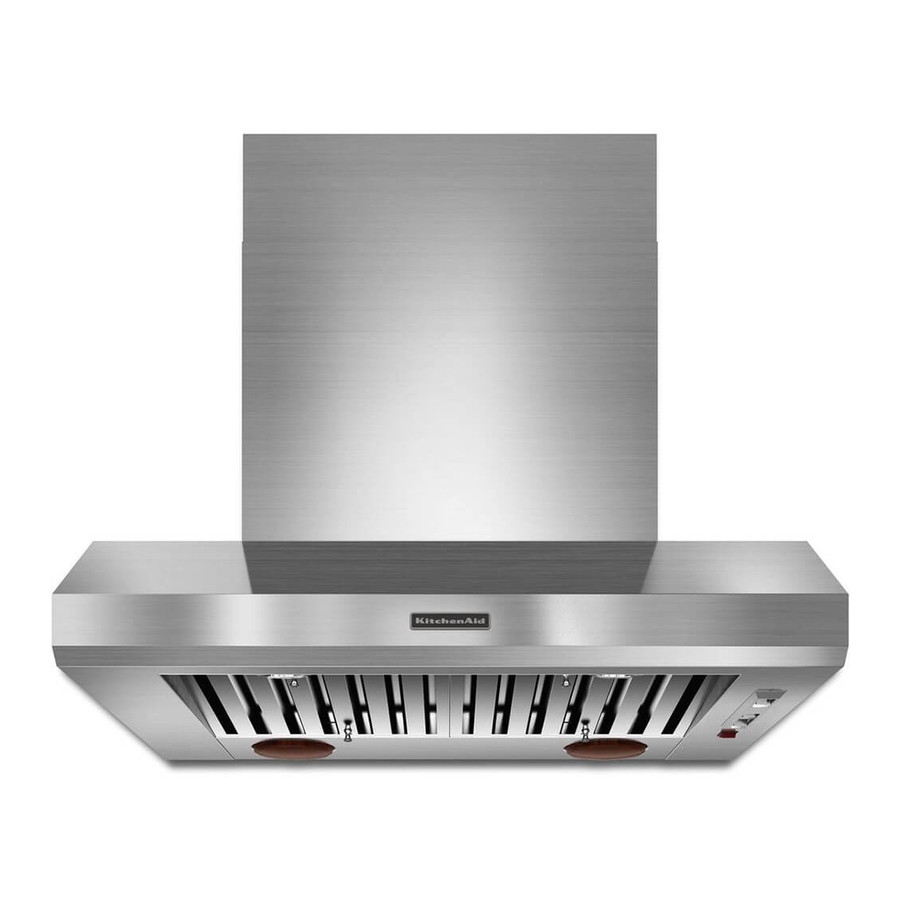
36" (91.4 CM) AND 48" (121.9 CM)
DESIGNER COMMERCIAL-STYLE ISLAND-
MOUNT CANOPY HOOD
Installation Instructions and Use & Care Guide
For questions about features, operation/performance, parts, accessories or service, call: 1-800-422-1230
or visit our website at www.kitchenaid.com
In Canada, for assistance, installation and service, call: 1-800-807-6777
or visit our website at www.KitchenAid.ca
HOTTE D'EXTRACTION STYLISÉE POUR
APPLICATIONS COMMERCIALES DE
36" (91,4 CM) ET 48" (121,9 CM) POUR CUISINE
CONFIGURÉE EN ÎLOT
Instructions d'installation et Guide d'utilisation et d'entretien
Au Canada, pour assistance, installation ou service composez le 1-800-807-6777
ou visitez notre site web à www.KitchenAid.ca
Table of Contents/Table des matières............................................................................. 2
IMPORTANT: READ AND SAVE THESE INSTRUCTIONS.
FOR RESIDENTIAL USE ONLY.
IMPORTANT : LIRE ET CONSERVER CES INSTRUCTIONS.
POUR UTILISATION RÉSIDENTIELLE UNIQUEMENT.
LI3ZHB/W10331010C
Advertisement
Table of Contents

Related Manuals for KitchenAid DESIGNER COMMERCIAL-STYLE ISLAND-MOUNT CANOPY HOOD


Summary of Contents for KitchenAid DESIGNER COMMERCIAL-STYLE ISLAND-MOUNT CANOPY HOOD
- Page 1 CONFIGURÉE EN ÎLOT Instructions d’installation et Guide d’utilisation et d’entretien Au Canada, pour assistance, installation ou service composez le 1-800-807-6777 ou visitez notre site web à www.KitchenAid.ca Table of Contents/Table des matières................2 IMPORTANT: READ AND SAVE THESE INSTRUCTIONS. FOR RESIDENTIAL USE ONLY.
-
Page 2: Table Of Contents
TABLE OF CONTENTS TABLE DES MATIÈRES RANGE HOOD SAFETY ..............2 SÉCURITÉ DE LA HOTTE DE CUISINIÈRE .......20 INSTALLATION REQUIREMENTS ..........4 EXIGENCES D'INSTALLATION ...........22 Tools and Parts ................4 Outils et pièces................22 Location Requirements ..............4 Exigences d'emplacement............22 Venting Requirements..............5 Exigences concernant l'évacuation ...........23 Spécifications électriques ............25 Electrical Requirements ...............6 INSTRUCTIONS D'INSTALLATION..........26... -
Page 3: Important Safety Instructions
IMPORTANT SAFETY INSTRUCTIONS WARNING: TO REDUCE THE RISK OF A RANGE TOP WARNING: TO REDUCE THE RISK OF FIRE, ELECTRIC GREASE FIRE: SHOCK, OR INJURY TO PERSONS, OBSERVE THE FOLLOWING: Never leave surface units unattended at high settings. Boilovers cause smoking and greasy spillovers that may Use this unit only in the manner intended by the ignite. -
Page 4: Installation Requirements
INSTALLATION REQUIREMENTS Horizontal support Tools and Parts 4 - 5 x 45 mm mounting screws Gather the required tools and parts before starting installation. 72 - 4.2 x 8 mm mounting screws Read and follow the safety instructions provided with any tools T-20 TORX ®†... -
Page 5: Venting Requirements
For the most efficient and quiet operation: Installation Clearances Use no more than three 90° elbows. Make sure there is a minimum of 24" (61 cm) of straight vent between the elbows if more than 1 elbow is used. Do not install 2 elbows together. Use clamps to seal all joints in the vent system. -
Page 6: Electrical Requirements
Typical In-line Blower Motor System Venting Installations Electrical Requirements Observe all governing codes and ordinances. Ensure that the electrical installation is adequate and in conformance with National Electrical Code, ANSI/NFPA 70 (latest edition), or CSA Standards C22.1-94, Canadian Electrical Code, Part 1 and C22.2 No. -
Page 7: Installation Instructions
INSTALLATION INSTRUCTIONS Complete Preparation Prepare Location It is recommended that the vent system be installed before 1. Determine the required location for the home power supply the range hood is installed. cable and drill a ½" (1.3 cm) diameter hole for wire access. Before making cutouts, make sure there is proper clearance 2. - Page 8 2. Install the transition piece using 3 - 4.2 x 8 mm mounting 6. Attach a second set of vertical supports (A) and set the vertical height (B). See “Installation Clearances” in the screws to the range hood canopy. “Location Requirements” section to help determine the 3.
-
Page 9: Install Range Hood Internal Blower Motor
Install Range Hood Internal Blower Motor NOTE: Your range hood requires you to purchase either an Five 6 mm nuts are required for the dual motor system. Clip nuts into the small square notches, one located in the internal type or an in-line (external type) blower motor system. front of the square vent opening and the other four See “Blower Motor System”... - Page 10 Dual Blower Motor Assembly 4. Push the right end of the motor mounting plate up and snap it into the spring tab. NOTE: The spring tab should be outside the slot in the mounting plate. A. Wiring connection 2. Slide the left mounting plate flange under the motor mounting bracket.
-
Page 11: Install Range Hood In-Line (External Type) Blower Motor
Install Range Hood In-Line (External Type) Blower Motor NOTE: Your range hood requires you to purchase either an 6. Pull the spring clip to release the blower motor assembly. internal type or an in-line (external type) blower motor system. Remove the blower motor assembly from the housing and See “Blower Motor System”... -
Page 12: Make Electrical Connections For In-Line Blower Motor System
Complete Preparation Make Electrical Connections for In-Line Blower Motor System 1. Determine and make all necessary cuts for the vent system. IMPORTANT: When cutting or drilling into the ceiling or wall, WARNING do not damage electrical wiring or other hidden utilities. 2. - Page 13 5. Connect the wires from the 6-wire connector assembly to the WARNING wires from the wiring conduit inside the range hood terminal box. 6. Connect the same color wires to each other (black to black, white to white, etc.) using UL listed wire connectors. NOTE: Connect the green (or green/yellow) ground wire from the wiring conduit to the green (or bare) ground wire from the home power supply using UL listed wire connectors (see the...
-
Page 14: Make Electrical Power Supply Connection To Range Hood
4. Use UL listed wire connectors and connect white wires (A) Make Electrical Power Supply Connection to together. Range Hood WARNING WARNING Electrical Shock Hazard Electrically ground blower. Electrical Shock Hazard Connect ground wire to green and yellow ground wire Disconnect power before servicing. -
Page 15: Complete Installation And Check Operation
4. Secure the lower chimney covers to the range hood canopy using 6 - 4.2 x 8 mm screws. Complete Installation and Check Operation 1. Install grease filters. See “Range Hood Care” section. 2. Check operation of the range hood blower and lights. See “Range Hood Use”... -
Page 16: Range Hood Controls
Metal Grease Filter Range Hood Controls To Remove Metal Grease Filters: Operating the light 1. Use 2 hands to remove the metal grease filters. Grasp filter handles, push toward the rear of the range hood and pull 1. Move the light switch to the “1” position to turn range hood down on the front handle to remove. -
Page 17: Wiring Diagram
WIRING DIAGRAM Junction box N L Gnd SE110A Fan speed Fan speed Light Speed 1 Temperature Closure Speed 2 sensor temperature: 167˚F±5.4˚F Speed 3 (75+/-3˚C) Opening temperature: ≥140˚F (60˚C) 25uF 25uF 9 10 Optional kit with 1 motor Lamps Motor Resistance (Ohms) Motor Characteristics Blue-Red: 18 Power absorption: 420 W... -
Page 18: Assistance Or Service
1200 CFM Internal Blower Motor System - Order Model Number For further assistance UXB1200DYS If you need further assistance, you can write to KitchenAid with 600 CFM In-Line Blower Motor System - Order Model Number any questions or concerns at:... -
Page 19: Warranty
KitchenAid brand of Whirlpool Corporation or Whirlpool Canada LP (hereafter “KitchenAid”) will pay for Factory Specified Parts and repair labor to correct defects in materials or workmanship. Service must be provided by a KitchenAid designated service company. This limited warranty is valid only in the United States or Canada and applies only when the major appliance is used in the country in which it was purchased. -
Page 20: Sécurité De La Hotte De Cuisinière
SÉCURITÉ DE LA HOTTE DE CUISINIÈRE Votre sécurité et celle des autres est très importante. Nous donnons de nombreux messages de sécurité importants dans ce manuel et sur votre appareil ménager. Assurez-vous de toujours lire tous les messages de sécurité et de vous y conformer. Voici le symbole d’alerte de sécurité. - Page 21 IMPORTANTES INSTRUCTIONS DE SÉCURITÉ AVERTISSEMENT : POUR MINIMISER LE RISQUE AVERTISSEMENT : POUR RÉDUIRE LE RISQUE D'UN FEU DE GRAISSE SUR LA CUISINIÈRE : D'INCENDIE, CHOC ÉLECTRIQUE OU DOMMAGES CORPORELS, RESPECTER LES INSTRUCTIONS Ne jamais laisser un élément de surface fonctionner à SUIVANTES : puissance de chauffage maximale sans surveillance.
-
Page 22: Exigences D'installation
EXIGENCES D'INSTALLATION Support horizontal Outils et pièces 4 vis de montage de 5 x 45 mm Rassembler les outils et composants nécessaires avant 72 vis de montage de 4,2 x 8 mm d’entreprendre l’installation. Lire et suivre les instructions de Adaptateur T-20 TORX ®†... -
Page 23: Exigences Concernant L'évacuation
Dégagements de séparation à respecter Exigences concernant l'évacuation Le système d'évacuation doit décharger l'air à l'extérieur. Ne pas terminer le système d'évacuation dans un grenier ou dans un autre espace fermé. Ne pas utiliser une bouche de décharge murale de 4"... - Page 24 Méthodes d'évacuation Calcul de la longueur effective du circuit d'évacuation Pour calculer la longueur effective du circuit d'évacuation Installations typiques avec système du moteur du nécessaire, additionner les longueurs équivalentes (pieds/mètres) ventilateur interne de tous les composants utilisés dans le système. Un circuit d'évacuation en conduit rond de 10"...
-
Page 25: Spécifications Électriques
Spécifications électriques Observer les dispositions de tous les codes et règlements en Si le domicile est équipé d'un câblage en aluminium, suivre vigueur. les instructions suivantes : Vérifier que l'installation électrique a été correctement effectuée 1. Connecter une section de câble en cuivre massif aux et qu'elle est conforme aux spécifications de la plus récente conducteurs en queue de cochon. -
Page 26: Instructions D'installation
INSTRUCTIONS D'INSTALLATION Préparation de l'emplacement Il est recommandé que l'installation du circuit d'évacuation Achever la préparation soit réalisée avant celle de la hotte. Avant d’exécuter les découpages, vérifier qu'il existe un 1. Déterminer l'emplacement nécessaire pour le câble dégagement suffisant dans le plafond pour le conduit d'alimentation du domicile et percer un trou de ½"... -
Page 27: Installation De La Hotte
Installation de la hotte REMARQUE : Il est nécessaire d'acheter un moteur de 4. Positionner les 4 supports verticaux (A) par rapport aux ventilateur interne ou externe (en ligne) avec votre hotte. encoches au bas et fixer la hotte à l’aide des 16 vis de 4,2 x 8 mm. -
Page 28: Installation Du Moteur Du Ventilateur Interne De La Hotte
9. Fixer les supports de cache-conduits verticaux à l'aide des 4 vis de 4,2 x 8 mm. A. 3 vis 4,2 x 8 mm pour le support de montage du moteur B. 2 vis 4,2 x 8 mm pour la languette à ressort du moteur A. - Page 29 3. Passer les câbles d'alimentation et le connecteur, à partir de Installation du moteur du ventilateur interne de la hotte la hotte, par le trou à droite de la plaque de montage du moteur. 1. Installer le moteur du ventilateur de la hotte à l'intérieur de la hotte.
-
Page 30: Installation Du Moteur Du Ventilateur En Ligne (Externe) De La Hotte
6. Brancher le connecteur de l’alimentation électrique de la 4. Débrancher la prise électrique du moteur de l'ensemble hotte au connecteur qui se trouve sur le boîtier de connexion moteur-ventilateur. de l’ensemble moteur-ventilateur. 5. Enlever les vis qui fixent l’ensemble moteur-ventilateur au carter du ventilateur et les mettre de côté. -
Page 31: Réalisation Des Connexions Électriques Du Système Du Moteur Du Ventilateur En Ligne
4. Réinstaller l’ensemble moteur-ventilateur s’il a été enlevé et le fixer avec les vis enlevées précédemment. Réalisation des connexions électriques du 5. Rebrancher le cordon de la fiche électrique du moteur au système du moteur du ventilateur en ligne connecteur de l’ensemble moteur-ventilateur s’il a été enlevé. AVERTISSEMENT Achever la préparation 1. -
Page 32: Connexion De L'alimentation Électrique À La Hotte
AVERTISSEMENT Risque de choc électrique Relier le ventilateur à la terre. Brancher le fil relié à la terre au fil vert et jaune relié à la terre dans la boîte de la borne. Le non-respect de ces instructions peut causer un A. -
Page 33: Installer Les Cache-Cheminée
Installer les cache-cheminée Installation du cache-cheminée 1. Ôter les protections en plastique des sections des cache- cheminée. 2. Installer les cache-cheminée en les faisant coulisser jusqu'à ce que les ressorts émettent un déclic. A. Conducteurs blancs B. Conducteurs noirs C. Connecteurs de fils (homologation UL) D. -
Page 34: Achever L'installation Et Vérifier Le Fonctionnement
3. Installer la section supérieure des cache-cheminée (fournis dans l’ensemble d’extension de cache-cheminée) en les Achever l'installation et vérifier le faisant coulisser jusqu'à ce que les ressorts émettent un fonctionnement déclic. 1. Installation des filtres à graisse. Voir la section “Entretien de la hotte”. -
Page 35: Utilisation De La Hotte
UTILISATION DE LA HOTTE La hotte de cuisinière est conçue pour extraire fumée, vapeurs de Fonctionnement du ventilateur cuisson et odeurs de la zone de la table de cuisson. Pour obtenir les meilleurs résultats, mettre le ventilateur de la hotte en marche avant d’entreprendre une cuisson, et laisser le ventilateur 1. -
Page 36: Entretien De La Hotte
ENTRETIEN DE LA HOTTE Nettoyage IMPORTANT : Nettoyer fréquemment la hotte et les filtres à Remplacement d’une lampe à halogène graisse en suivant les instructions suivantes. Réinstaller les filtres à graisse avant de faire fonctionner la hotte. Interrompre l’alimentation de la hotte; attendre le refroidissement Surfaces externes : de la lampe à... -
Page 37: Schéma De Câblage
SCHÉMA DE CÂBLAGE Boîtier de connexion Neu L Terre SE110A Marche Arrêt Marche Arrêt Arrêt Vitesse du ventilateur Vitesse du ventilateur Ventilateur Ventilateur Lampe Vitesse 1 Capteur de température Vitesse 2 Température de fermeture : 167˚F±5,4˚F Vitesse 3 (75+/-3˚C) Température d'ouverture : ≥140˚F (60˚C) 25uF... -
Page 38: Assistance Ou Service
Système du moteur du ventilateur en ligne de 1200 CFM - pièces de rechange et aux compagnies de service. Les Commander le modèle numéro UXI1200DYS techniciens de service désignés par KitchenAid Canada sont formés pour remplir la garantie des produits et fournir un service après la garantie, partout au Canada. -
Page 39: Garantie
5. Les défauts apparents, notamment les éraflures, les bosses, fissures ou tout autre dommage au fini du gros appareil ménager, à moins que ces dommages soient dus à des vices de matériaux ou de fabrication et soient signalés à KitchenAid dans les 30 jours suivant la date d’achat. - Page 40 © 2011. All rights reserved. ® Registered Trademark/TM Trademark of KitchenAid, U.S.A., KitchenAid Canada licensee in Canada Printed in Mexico Tous droits réservés. ® Marque déposée/TM Marque de commerce de KitchenAid, U.S.A., Emploi sous licence par KitchenAid Canada au Canada Imprimé au Mexique...
Need help?
Do you have a question about the DESIGNER COMMERCIAL-STYLE ISLAND-MOUNT CANOPY HOOD and is the answer not in the manual?
Questions and answers