Table of Contents
Advertisement
0-56r
O
n
L
i
n
O
n
L
i
n
GENERAL SAFETY INSTRUCTIONS
Warnings in this manual appear in any of four ways:
POWERVAR Security Plus UPS
S
e
c
u
r
S
e
c
u
r
e
U
n
i
n
t
e
r
r
u
p
e
U
n
i
n
t
e
r
r
u
U
s
e
r
I
n
s
t
r
u
U
s
e
r
I
n
s
t
r
u
1
i
t
y
P
l
u
s
i
t
y
P
l
u
s
t
i
b
l
e
P
o
w
e
p
t
i
b
l
e
P
o
w
e
c
t
i
o
n
M
a
n
u
c
t
i
o
n
M
a
n
u
r
S
u
p
p
l
y
r
S
u
p
p
l
y
a
l
a
l
Advertisement
Table of Contents

Related Manuals for Powervar Security Plus


Summary of Contents for Powervar Security Plus
- Page 1 POWERVAR Security Plus UPS 0-56r GENERAL SAFETY INSTRUCTIONS Warnings in this manual appear in any of four ways:...
- Page 2 POWERVAR Security Plus UPS Danger- The danger symbol is a lightning bolt mark enclosed in a triangle which precedes the 3/16-inch high letters spelling the word “DANGER”. The danger symbol is used to indicate imminently hazardous situations, locations, and conditions which, if not avoided, WILL result in death, serious injury, and/or severe property damage.
- Page 3 POWERVAR Security Plus UPS Protective earth (Ground) N Connection point for the neutral conductor on PERMANENTLY INSTALLED EQUIPMENT Earth Ground...
- Page 4 POWERVAR Security Plus UPS To ensure correct operation of the UPS, please read this instruction manual carefully. Please keep this manual handy for future reference. This UPS has dangerously high voltages on both its Input and output connections. Contact with these voltages may be life threatening.
- Page 5 POWERVAR Security Plus UPS The UPS should only be serviced or maintained by a factory authorized service technician. This UPS meets FCC Class A electromagnetic compatibility requirements. Depleted batteries must be disposed of in a proper manner. Contact your local recycling or hazardous waste center or the UPS manufacturer for instructions concerning proper disposal.
-
Page 6: Table Of Contents
1.3 Performance Specifications ............8 2.0 Structure and Basic Principles 2.1 General Structure ..............30 2.1.1 Security Plus Front Panel and Rear Panel Structure ....30 2.1.2 Security Plus Display/Controls Operation ......... 31 2.1.3 Security Plus Terminal Connection Block Illustration (2-6kVA) ..35 2.1.4 Security Plus Terminal Connection Block Illustration (8-15kVA) ... -
Page 7: Overview
POWERVAR Security Plus UPS The Security Plus UPS is a high frequency, double conversion (true online) intelligent UPS for use with file servers, enterprise servers, microcomputers, telecommunication systems, data centers, laboratory instrumentation, and other microprocessor-based equipment that requires high quality, conditioned uninterruptible power. It is designed for use in telecom, IT, LAN, banking and financial, or almost any application where the performance of computer systems is mission critical. -
Page 8: Performance Specifications
11. DC voltage is still present on the battery fuses even with the UPS turned off. The battery trays must be removed before servicing UPS. 1.3 Performance Specifications The major specifications of the Security Plus UPS are shown in the individual specification sheets on the following pages. Note: Specifications are subject to change without notice. - Page 9 POWERVAR Security Plus UPS 11.80 32.65 (299.72) (829.4) 28.70 (729.0) FRONT SIDE REAR Model ABCDEF2000-11 ABCDEF2000-22 Topology True On line, Double-Conversion, IGBT Design, Internal Isolation Transformer Voltage (VAC) Voltage Range (VAC) 70-115 81-132 84-138 140-230 146-239 154-253 161-264 168-276 Voltage Tolerance...
- Page 10 POWERVAR Security Plus UPS Voltage (VDC) 96.0, nominal 109.2, float Battery 12V, 34W flame retardant High Rate, Sealed Lead-Acid Quantity Charge Current (ADC) Backup Time (min) > 7.0 Recharge Time 8 hours to 90% Temperature (°C) 0 to 40, operating...
- Page 11 Batteries are warranted for a period of two years from the date of shipment for standby use; 90 days for cyclic use. For North American service or support on any POWERVAR product, please contact POWERVAR Technical Support at (800) 369-7179 (in Illinois call (847-596-7000).
- Page 12 POWERVAR Security Plus UPS 11.80 32.65 (299.72) (829.4) 28.70 (729.0) FRONT SIDE REAR Model ABCDEF3000-11 ABCDEF3000-22 Topology True On-line, Double-Conversion, IGBT Design, Internal Isolation Transformer Voltage (VAC) Voltage Range (VAC) 70-115 81-132 84-138 140-230 146-239 154-253 161-264 168-276 Voltage Tolerance...
- Page 13 POWERVAR Security Plus UPS Voltage (VDC) 96.0, nominal 109.2, float Battery 12V, 34W flame retardant High Rate, Sealed Lead-Acid Quantity Charge Current (ADC) Backup Time (min) > 12.0 Recharge Time 8 Hours to 90% Temperature (°C) 0 to 40, operating...
- Page 14 Batteries are warranted for a period of two years from the date of shipment for standby use; 90 days for cyclic use. For North American service or support on any POWERVAR product, please contact POWERVAR Technical Support at (800) 369-7179 (in Illinois call (847-596-7000).
- Page 15 POWERVAR Security Plus UPS 11.80 32.65 (299.7 (829.4) 28.70 (729.0) FRONT SIDE REAR Model ABCDEF4000-22 Topology True On-Line, Double-Conversation, IGBT Design, Internal Isolation Transformer Voltage (VAC) Voltage Range (VAC) 140-230 146-239 154-253 161-264 168-276 Voltage Tolerance + 15% ~ -30% before switching to batteries...
- Page 16 POWERVAR Security Plus UPS Voltage (VDC) 96.0, nominal 109.2, float Battery 12V, 34W flame retardant High Rate, Sealed Lead-Acid Quantity Charge Current (ADC) Backup Time (min) > 8.0 Recharge Time 8 Hours to 90% Temperature (°C) 0 to 40, operating...
- Page 17 Batteries are warranted for a period of two years from the date of shipment for standby use; 90 days for cyclic use. For North American service or support on any POWERVAR product, please contact POWERVAR Technical Support at (800) 369-7179 (in Illinois call (847-596-7000).
- Page 18 POWERVAR Security Plus UPS 11.80 32.65 (299.72) (829.4) 28.70 (729.0) FRONT SIDE REAR Model ABCDEF5200-22 Topology True On-Line, Double-Conversion, IGBT Design, Internal Isolation Transformer Voltage (VAC) Voltage Range (VAC) 140-230 146-239 154-253 161-264 168-276 Voltage Tolerance + 15% ~ -30% before switching to batteries...
- Page 19 POWERVAR Security Plus UPS Voltage (VDC) 96.0, nominal 109.2, float Battery 12V, 34W flame retardant High Rate, Sealed Lead-Acid Quantity Charge Current (ADC) Backup Time (min) > 6.0 Recharge Time 8 Hours to 90% Temperature (°C) 0 to 40, operating...
- Page 20 Batteries are warranted for a period of two years from the date of shipment for standby use; 90 days for cyclic use. For North American service or support on any POWERVAR product, please contact POWERVAR Technical Support at (800) 369-7179 (in Illinois call (847-596-7000).
- Page 21 POWERVAR Security Plus UPS 11.80 32.65 (299.72) (829.4) 28.70 (729.0) FRONT SIDE REAR Model ABCDEF6000-22 Topology True On-Line, Double-Conversion, IGBT Design, Internal Isolation Transformer Voltage (VAC) Voltage Range (VAC) 140-230 146-239 154-253 161-264 168-276 Voltage Tolerance + 15% ~ -30% before switching to batteries...
- Page 22 POWERVAR Security Plus UPS Voltage (VDC) 96.0, nominal 109.2, float Battery 12V, 34W flame retardant High Rate, Sealed Lead-Acid Quantity Charge Current (ADC) Backup Time (min) > 5.0 Recharge Time 8 Hours to 90% Temperature (°C) 0 to 40, operating...
- Page 23 Batteries are warranted for a period of two years from the date of shipment for standby use; 90 days for cyclic use. For North American service or support on any POWERVAR product, please contact POWERVAR Technical Support at (800) 369-7179 (in Illinois call (847-596-7000).
- Page 24 POWERVAR Security Plus UPS 13.77 38.61 (349.76) (980.61) 33.46 (850.00) FRONT SIDE REAR Model ABCDEF8000-22 ABCDEF10.0-22 Topology True On line, Double-Conversion, IGBT Design, Internal Isolation Transformer Voltage (VAC) Voltage Range (VAC) 140-230 146-239 154-253 161-264 168-276 Voltage Tolerance + 15% ~ -30% before switching to batteries...
- Page 25 POWERVAR Security Plus UPS Input Voltage (VAC) Output Voltage (VAC) Transformer Voltage ± 3.0% Regulation 125% for 10 minutes Overload 150% for 500ms 1000% for 1 cycle Efficiency > 95.0% Voltage (VDC) 288.0, nominal 327.6, float Battery 12V, 34W flame retardant...
- Page 26 POWERVAR product, please contact POWERVAR Technical Support at (800) 369-7179 (in Illinois call (847-596-7000). For service and support in EMEA, contact POWERVAR, Ltd. in the United Kingdom at +44 (0) 1793 553980. Or visit the POWERVAR website at www.powervar.com.
- Page 27 POWERVAR Security Plus UPS 15.75 44.39 (400.0) (1127.54) 42.53 (1080.2) FRONT SIDE REAR Model ABCDEF12.0-22 ABCDEF15.0-22 Topology True On line, Double-Conversion, IGBT Design, Internal Isolation Transformer Voltage (VAC) Voltage Range (VAC) 140-230 146-239 154-253 161-264 168-276 Voltage Tolerance + 15% ~ -30% before switching to batteries...
- Page 28 POWERVAR Security Plus UPS Input Voltage (VAC) Output Voltage (VAC) Transformer Voltage ± 3.0% Regulation 125% for 10 minutes Overload 150% for 500ms 1000% for 1 cycle Efficiency > 95.0% Voltage (VDC) 288.0, nominal 327.6, float Battery 12V, 34W flame retardant...
- Page 29 Batteries are warranted for a period of two years from the date of shipment for standby use; 90 days for cyclic use. For North American service or support on any POWERVAR product, please contact POWERVAR Technical Support at (800) 369-7179 (in Illinois call (847-596-7000).
-
Page 30: Structure And Basic Principles
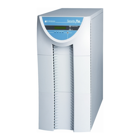
UPS covers or perform maintenance tasks. 2.1 General Structure 2.1.1 Security Plus Front Panel and Rear Panel Structure The operator panel layout of the Security Plus UPS is illustrated in Fig. 2-1 and Table 2-1. Figure 2-1 Item... -
Page 31: Security Plus Display/Controls Operation
2.1.2 Security Plus Display/Controls Operation The menu visible in the LCD display of the Security Plus UPS is illustrated in Fig. 2-2 and 2-3. The various LCD displays are accessed using the front panel controls of the UPS as follows: Function Button Explanation The NORMAL/BYPASS button is used to start and stop the inverter. - Page 32 POWERVAR Security Plus UPS Figure 2.2 – Display Verbiage If the NORMAL/BYPASS button is pushed and the AC input is out of range, the system will start up in If the AC input condition is out of battery operation mode and range, then the system will display SECURITY PLUS continue until AC returns to normal ‘UPS Start Up’. There is no output in MODEL NUMBER range or batteries become depleted. this condition Press OPERATION OPERATON ‘NORMAL/BYPASS’ UPS START UP BATTERY MODE The system will automatically switch to ONLINE mode If the AC input condition is in range.
- Page 33 POWERVAR Security Plus UPS Figure 2.3 – Parameters Setting Menu If the ‘SELECT’ button is INVERTER OFF Press ‘OK’ The inverter will be shut down pushed and held for 3 YES? and the output will turn off. AC seconds the parameter...
- Page 34 Hot swappable cooling fans Connection point for rear receptacle panel Main supply and battery switches (circuit breakers) Table 2-2 Figure 2-4 The front and rear panel layout of the Security Plus UPS is illustrated in Fig. 2-4 and Table 2-2.
-
Page 35: Security Plus Terminal Connection Block Illustration (2-6Kva)
POWERVAR Security Plus UPS 2.1.3 Security Plus Terminal Connection Block Illustration (2-6kVA) All models are factory configured for 50 or 60Hz operation. Figure 2-5A represents 2-6kVA 60Hz configuration. Figure 2-5B represents 2-6kVA 50Hz configuration. Refer to Table 2-3 or Table 2-4 for the appropriate wiring configuration. - Page 36 POWERVAR Security Plus UPS For North American applications, high voltage models may be configured for an input voltage of either 200, 208 or 240 volts at 50 or 60 Hz. Output voltage for these models is available at 115,120, 200, 208 and 240 volts at 50 or 60 Hz. Table 2-3 illustrates how to connect to the terminal block in Figure 2-5A to achieve the desired input and output voltage configurations.
- Page 37 POWERVAR Security Plus UPS For field wired units, refer to the tables below for the proper conductor size and torque requirements. Only copper conductors are to be used for field wiring connections. The conductors should be rated at least 75°C or greater. The conductor recommendations listed in the chart below are intended for installations in North America.
-
Page 38: Security Plus Terminal Connection Block Illustration (8-15Kva)
POWERVAR Security Plus UPS 2.1.4 Security Plus Terminal Connection Block Illustration (8-15kVA) All models are factory configured for 50 or 60Hz operation. For the 8-15kVA, the input wires are directly connected to the AC input circuit breaker. The wire connection (from left to right) of the terminal connection block on the rear is shown... - Page 39 POWERVAR Security Plus UPS For field wired units, refer to table 2-4C for the proper conductor size and torque requirements. Only copper conductors are to be used for field wiring connections. The conductors should be rated at least 75ºC or greater. The conductor recommendations listed in the chart below are intended for installations in North America.
- Page 40 All Powervar Hardwired Security Plus UPS system’s OUTPUT must be protected by proper sized AC disconnect device. The recommended disconnect device ratings at full rated load are listed...
-
Page 41: Rs232 Communications
DB9 male connector on the rear of the UPS. The chart above shows the pin assignment for each signal. The EPO (emergency power off) contact is a normally closed 125 VAC circuit. When wiring to the EPO a properly sized switch must be used. Contact POWERVAR with any questions 2.2 Basic Principles... - Page 42 POWERVAR Security Plus UPS ISOLATION LOAD 240Vac DC/AC PFC AC/DC TRANSFORMER DC/DC BATTERY CHARGE Figure 2-8—Normal Operation Mode ISOLATION LOAD 240Vac DC/AC PFC AC/DC TRANSFORMER DC/DC BATTERY CHARGE Figure 2-9—Battery Operation Mode ISOLATION LOAD 240Vac DC/AC PFC AC/DC TRANSFORMER DC/DC...
-
Page 43: Equipment Installation
POWERVAR Security Plus UPS 3.1 Site and Environment Requirements Before beginning installation of the UPS, the environment where the UPS is to be installed must meet reasonable standards for safe and normal operation as defined in this section. If the installation site conditions do not meet the minimum requirements of safe equipment operation, corresponding changes to the site conditions should be made. - Page 44 POWERVAR Security Plus UPS Security Plus Unpacking Instructions For 2-6kVA Models The UPS is packed in a heavy duty inner cardboard carton inside a larger plywood shipping container. Both carton and container are securely attached to a heavy duty shipping pallet. The packing materials may be retained for use in shipping the UPS to another location.
- Page 45 POWERVAR Security Plus UPS Security Plus Unpacking Instructions For 8-15kVA Models The UPS is packed in a heavy duty cardboard carton. The carton is securely attached to a heavy duty shipping pallet. The packing materials may be retained for use in shipping the UPS to another location.
-
Page 46: Installation Of Ups
POWERVAR Security Plus UPS 3.3 Installation of UPS For convenient operation, maintenance, and cooling of the equipment, there should be at least 30cm to 50cm (approximately 12” to 20”) of free space around the UPS enclosure and 50cm (approximately 20”) above the UPS enclosure. Be careful that vent openings and UPS fans are kept clear and free of obstructions to ensure good interior ventilation. -
Page 47: Equipment Use And Maintenance
POWERVAR Security Plus UPS 4.1 Preparation for Start-up To ensure proper operation of the UPS, please confirm the following before use: 1. Correct installation of input and output wiring connections. (See section 2.1.3 or 2.1.4) 2. Please verify the UPS is setup for the correct voltage. The label on the rear of the unit will indicate the factory input voltage setting. -
Page 48: Frequent Trouble Causes
POWERVAR Security Plus UPS As long as the UPS is connected to a live power source and the UPS input circuit breaker and battery circuit breaker is turned on, the UPS battery will be kept in a charged state. 1. Batteries of different capacity, type, and brand should not be used together. The manufacturer has approved only the type, capacity, and brand of battery originally shipped with the UPS. - Page 49 POWERVAR Security Plus UPS Problem 3 UPS displays and UPS output are normal after start-up. However, the output stops as soon as load is connected to it. Possible cause #1: UPS is experiencing a severe overload or a circuit short circuit on the output.
-
Page 50: Troubleshooting
POWERVAR Security Plus UPS Solution: 1) Press and hold the SELECT button until the screen displays “Inverter Off: Yes?” 2) Press SELECT button two more times until screen displays “Ground Fault: Disable?” 3) Press OK 4) Press the NORMAL/BYPASS button and wait 2 minutes (It is important to wait the 2 minutes). - Page 51 POWERVAR Security Plus UPS Problem: UPS works properly when power supply is O.K., but it fails to function during power failure. Possible cause 1: Battery circuit breaker is open (Off) Solution: Close (turn on) battery circuit breaker Possible cause 2: Battery failure Possible cause 3: Battery charger malfunction Possible cause 4: Poor contact between battery connecting wires or connecting terminals.
-
Page 52: Precautions
Solution: Contact distributor or manufacturer. 5.1 Precautions Servicing of batteries should be performed or supervised by personnel knowledgeable about batteries and the required precautions. (Please contact Powervar for Battery Replacement) When replacing batteries, replace with the same type and number of batteries or battery packs. -
Page 53: Battery Tray Replacement (2-6Kva)
Pull out battery tray (1), then tray (2), then tray (3), then tray (4) out of the unit Position detached battery trays away from one another when servicing Slide the new POWERVAR battery trays into the empty slots Battery cables are located in between the battery trays. Examine all battery connections to ensure that there are no loose or damaged connections prior to connecting battery trays. -
Page 54: Battery Tray Replacement (2-6Kva)
Lift the rear of the tray to remove the tray from the battery compartment. Repeat steps 2-4 for additional battery trays. Slide the new POWERVAR battery trays into the empty slots. Make sure the trays are secure and re-connect the battery tray connectors in the front of the unit. -
Page 55: Battery Tray Replacement (8-15Kva)
Lift the rear of the tray to remove the tray from the battery compartment. Repeat steps 2-4 for additional battery trays. Slide the new POWERVAR battery trays into the empty slots. Make sure the trays are secure and re-connect the battery tray connectors in the front of the unit. -
Page 56: Packing, Transportation And Storage
6.4 Fuse Replacements The servicing of any fuses in a Security Plus UPS system should be performed by an authorized and qualified service technician. When replacing a fuse, it is imperative that the replacement fuse is the same type and rating. Charger PCB fuses: F1, F2: are a 250V, 5.0 amp fuse. The control PCB fuse is a 125V, 0.25 amp fuse. -
Page 57: Mechanical Characteristics
POWERVAR Security Plus UPS 7.1 Unit Dimensions/Weights Model Height Width Depth Unit Weight in/mm in/mm in/mm lbs/kg ABCDEF2000-11 28.7/735.5 11.8/299.72 32.65/829.3 215/97 ABCDEF2000-22 28.7/735.5 11.8/299.72 32.65/829.3 221/100 ABCDEF3000-11 28.7/735.5 11.8/299.72 32.65/829.3 294/132 ABCDEF3000-22 28.7/735.5 11.8/299.72 32.65/829.3 300/135 ABCDEF4000-22 28.7/735.5 11.8/299.72 32.65/829.3... -
Page 58: Basic Warranty
POWERVAR Security Plus UPS 8.1 Basic Warranty Security Plus Series products (hereafter referred to as “Product”) are warranted to be free from defects in material and workmanship for three (3) years from date of shipment from POWERVAR, on the chassis & electronic components and two (2) years from date of shipment from POWERVAR on the batteries. - Page 59 POWERVAR Security Plus UPS North American address: 1450 Lakeside Drive Waukegan, IL 60085 Toll Free: (800) 369-7179 Inside Illinois: (847) 596-7000 Fax: (847) 596-7100 International address: Unit 5, Birch-Kembrey Park Swindon, Wilts SN2 8UU UK (PH#) +44 1793 553980 (FAX) +44 1793 535350 www.powervar.com...
Need help?
Do you have a question about the Security Plus and is the answer not in the manual?
Questions and answers