Table of Contents
Advertisement
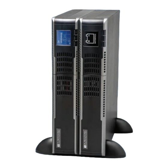
POWERVAR Sinergy III Rackmount / Tower User Instruction Manual
IMPORTANT SAFETY INSTRUCTIONS
SAVE THESE INSTRUCTIONS.
This manual contains important instructions for models :
Follow these instructions during the unpacking, installation, and maintenance of the UPS. If
you have a problem with the UPS, please refer to this manual before calling technical services.
POWERVAR
1450 South Lakeside Drive
Waukegan, IL 60085-8301
T (847) 596-7000
(800) 369-7179
F (847) 596-7100
A01-00027 Rev. A
· ACDEF6000-22
6KVA UPS
· E240-22-A
BATTERY CABINET
Advertisement
Table of Contents

Subscribe to Our Youtube Channel
Related Manuals for Powervar ACDEF6000-22


Summary of Contents for Powervar ACDEF6000-22
-
Page 1: Important Safety Instructions
POWERVAR Sinergy III Rackmount / Tower User Instruction Manual IMPORTANT SAFETY INSTRUCTIONS SAVE THESE INSTRUCTIONS. This manual contains important instructions for models : · ACDEF6000-22 · E240-22-A 6KVA UPS BATTERY CABINET Follow these instructions during the unpacking, installation, and maintenance of the UPS. If you have a problem with the UPS, please refer to this manual before calling technical services. - Page 2 A01-00027 Rev. A...
-
Page 3: Table Of Contents
Table of Contents 1. Introductio………………………………………………………………………………………… 1-1. Technical Support ……………………………………………………………………………………..1-2. FCC Compliance ………………………………………………………………………………………. 1-3. Safety …………………………………………………………………………………………………. .. 1-3-1. Safety Intended Use ………………………………………………………………………………….. 1-3-2. Safety Notices……………………………………………………………………………………. ….. 1-4. Emergency ……………………………………………………………………………………………… 1-5. Leakage Currents …………………………………………………………………………………. …... 1-6. Radio Interference ……………………………………………………………………………………... 1-7. Batteries ……………………………………………………………………………………………….. 1-8. - Page 4 . Operations (cont) 3-5-4. Charge the batteries …………………………………………………………………………………. 3-5-5. Battery mode operation ……………………………………………………………………………... 3-5-6. Test the batteries …………………………………………………………………………………….. 3-5-7. Turn off the UPS with utility power supply in Line mode………………………………………….. 3-5-8. Turn off the UPS without utility power supply in battery mode ……………………………………. 3.6.
-
Page 5: Introductio
(800) 369-7179 F (847) 596-7100 Please check with POWERVAR Service for assistance ordering, replacing, or disposing of Batteries. Please check with POWERVAR Service before attempting to repair or return any POWERVAR product. If a POWERVAR UPS needs repair or replacement, Service will issue a Return Material Authorization (RMA) number along with instructions on how to return the UPS. -
Page 6: Safety Notices
WARNING: POWERVAR considers the safety of personnel to be of paramount importance. For this reason it is essential that procedures relating to safety be studied before commencing work, and properly adhered to thereafter. · The User or Operator may intervene in the operation of the UPS provided that the instructions laid out in “Batteries”... -
Page 7: Emergency
The UPS is connected to a DC energy source (battery). The output terminals may be live when the UPS is · not connected to an AC supply. Emergency Power Off (EPO) input is located on the rear of the unit (see Figure 11 on page 13). When this ·... -
Page 8: Repackaging
UPS. 1-10. Device Overview The following table provides an overview of the various versions of the device: Table 1: Overview of UPS devices and batteries Sinergy III UPS Model ACDEF6000-22-1 Battery Cabinet Model E240-22-A Type Order No. Nominal Power... -
Page 9: Symbols
Note: Sinergy III model ACDEF6000-22-1 may be provided with a maximum of eight extension battery cabinets. Sinergy III model ACDEF6000-22-4 may be provided with a maximum of fourteen extension battery cabinets. 1-11. Symbols The following symbols are used in this handbook: WARNING: indicates instructions which, if not observed, may endanger your life, your health, the reliability of your device or the security of your data. -
Page 10: Handling
Unpack the package and check the package contents. The shipping package contains: UPS Shipping Package Battery Shipping Package 1. One UPS 1. One Battery cabinet 2. One user manual 2. One Battery cable 3. Rail kit 3. Two Mounting ears 4. -
Page 11: Rack/Tower Installation
2. Rack/Tower Installation 2-1. Tower Installation The UPS system is shipped with two sets of feet and 6 extensions (2 short extensions plus 4 long extensions) that can be used to install the UPS module in the Tower configuration. A. Install Stand-a-lone. Refer to Figure 1. Assemble two feet and one short extension as one tower stand as shown in Step 1. -
Page 12: Rack Installation
2-2. Rack Installation 2-2-1. Attaching the Mounting Ears Attach the mounting ears to the side mounting holes of UPS or the battery bank using the screws provided. The ears should be oriented as shown in Figure 3 below. Figure 3 2-2-2. -
Page 13: Assembly Steps
2-2-3. Assembly Steps Step 1: Use 4 M6 screws to mount the right and left rail sliders to the two front posts of the four-post rack. Refer to Figure 5 below. Figure 5 Step 2. Use 4 M6 screws to mount the right and left rail sliders to the two back posts of the four-post rack. Refer to Figure 6 below. - Page 14 Step 4: Slide the UPS with its right and left ears attached onto the rail guide until the ears are in contact with the front of the rail guide. Refer to Figure 8 below. Figure 8 Step 5: Fasten each ear to the rack with the the M6 screws. Refer to Figure 9 below. Figure 9 Step 6: Assembly complete.
-
Page 15: Electrical Preparations For Ups Installation
2-3. Electrical Preparations for UPS Installation Installation and wiring must be performed in accordance with the local electric laws/regulations by authorized technical personnel only. Make sure the mains wire and breakers in the building are enough for the rated capacity of UPS to avoid the haz- ards of electric shock or fire. -
Page 16: Cable Sizes And Current
2-3-3. Cable Sizes and Current following table indicates the recommended sizes of conductors in accordance with the NEC®. (air temperature surrounding the conduits not greater than 104°F (40°C).) NOTE: Cable sizes are suggested and based on standard configurations. Installed input/output wiring for the UPS should be able to withstand over 40 amps of current. - Page 17 Figure 11: UPS Rear Panel View Figure 12: Battery Rear Panel Legend 1. RS-232 communication port 11. Input/output terminal block 2. USB communication port 12. Input terminals 3. EPO (Emergency Power Off) connector 13. Input ground terminal 4. Share current port (for parallel function) 14.
-
Page 18: Connecting Mains And Load Cables
2-4. Connecting Mains and Load Cables Installation and wiring must be performed in accordance with the local electric laws/regulations and execute the following instructions by professional personnel. Make sure the mains wire and breakers in the building are enough for the rated capacity of UPS to avoid the haz- ards of electric shock or fire. - Page 19 Figure 13. Input, Output and Ground connections to the UPS (shown with strain relief) Warning: Make sure the UPS is not turned on before installation. The UPS should not be turned on during wiring con- nection. Do not try to modify the standard model to the long-run model. Particularly, do not try to connect the standard battery cabinet to a non-standard external battery.
-
Page 20: Operations
3. OPERATIONS 3-1. Operating Mode/Status Description Mode/Status Description UPS Power On When UPS is powered on, it will enter into this mode for a few seconds for initializing the system. AC Mode When the input voltage is within acceptable range, and the UPS is turned on (the in- verter is running), the UPS will provide pure and stable sine wave AC voltage. -
Page 21: Button Operation
3-2. Button Operation There are 4 buttons on the front panel, Button Function ON/ENTER Press this button to turn on the UPS. Or press it to confirm the selection in the menu. OFF/ESC Press this button to turn off the UPS. Or press it to return to last menu. -
Page 22: Led Indicators
3-3. LED Indicators 3-4. Audible Alarm UPS status Buzzer status Mute Control Bypass mode Beeping once every 2 minutes Battery / Battery-test mode (normal battery voltage) Beeping once every 4 seconds Battery / Battery-test mode (low battery voltage) Beeping once every second... -
Page 23: Turn On The Ups Without Utility Power Supply ( To Battery Mode)
3-5-2 . Turn on the UPS without the utility power supply (to Battery mode) 1) Make sure the battery is connected and that the battery pack breaker is in the “ON” position. 2) Press the “ON/ENTER” button to start up the internal power. The UPS will enter into Bypass mode without output. -
Page 24: Battery Mode Operation
3-5-5 . Battery mode operation 1) When the UPS is in Battery mode, the buzzer will beep according to the battery capacity. Normally, the buzzer will beep once every 4 seconds. When the battery voltage drops to the alarm level, the buzzer will beep once per second, and the UPS will soon automatically shut down. -
Page 25: Turn Off The Ups Without Utility Power Supply In Battery Mode
3-5-8 . Turn off the UPS without utility power supply in Battery mode 1) With the LCD on the home page, press the “OFF/ESC” button. The LCD will show a prompt page of “Turn Off”. Move the arrow to “Yes” using the up or down button, then press “ON/ENTER”. The UPS will turn off and go to bypass mode with beeping once. -
Page 26: Lcd Operation
3-6. LCD Operation The entire LCD structure is demonstrated in the diagram below:... -
Page 27: Main Interface (Home Page)
3-6-1 . Main interface (home page) Bypass Mode Bypass Mode IP : 208.0V / 50.0Hz IP : 208.0V / 50.0Hz OP : 208.0V / 50.0 Hz OP : 208.0V / 50.0 Hz Batt : 273.0V / 99% Batt : 273.0V / 99% Load : Load : Warning : 01... - Page 28 3-6-2-2. Control Control : Turn On Batt Test Mute Para Unlock NOTE 1: “Para Unlock” appears only when a parallel communication failure occurs. NOTE 2: “Turn On” will be displayed if UPS is not turned on. “Turn Off” will be displayed if UPS is turned on. Generally speaking, these two messages will not be displayed at the same time or in all operation modes.
- Page 29 2) Battery Test This item will test the performance of the battery. This item will be displayed under all UPS modes. However, the battery test cannot be executed if the UPS is in Battery/Fault mode (a reminder will pop up in the screen). When the battery test is selected, the screen will return back to the home page with “Battery Test Mode”...
- Page 30 3-6-2-3 . Measurement Measurement displays the measured value of the parameters such as voltage / current / frequency / power / capac- ity / time etc. Press the “UP” or “DOWN” button to explore the pages. Input : Output : Battery : Volt : 208.0V...
- Page 31 3-6-2-4 . Information Information displays the value and status of all parameter settings. Press the “UP” or “DOWN” button to explore the pages. Bypass : ECO : Output : Status : Open Status : Open Volt : 208V Enable HighLoss V : 232V Freq : Auto...
- Page 32 1) Bypass setting Interface Description 1. Status (only available in bypass / AC mode) 1.1 Open / Forbid : Open : Bypass allowed. When selected, UPS will run in Bypass mode depending on bypass enabled/disabled setting. Forbid : Bypass not allowed. When selected Bypass mode is not allowed Bypass : under any situation.
- Page 33 2) Output setting (only available or effective on bypass mode) Interface Description 1. Volt : 200 : Sets the output voltage to 200Vac 208 : Sets the output voltage to 208Vac 220 : Sets the output voltage to 220Vac 230 : Sets the output voltage to 230Vac 240 : Sets the output voltage to 240Vac Output : 2.
- Page 34 3) Battery setting (available in all operational modes) Interface Description 1. Dischg Protect : Battery : Enable : Battery discharge protection function is enabled. When the DisChg Protect : UPS has been continuously operating in “battery/battery test mode”, the Enable UPS will automatically shut down when the discharge time set by option 990 Minute 1.2 below has expired.
- Page 35 4) Calibration (for authorized service personel only) Interface Description 1. Batt : Calibrate the battery voltage measurement. Calibration Calibration : range is from 0V to 5.7V. The default value is 0V. Batt : 273.0 +0.0 Battery calibration is available in all operational modes. Inv : 209.0 +0.0 2.
- Page 36 Interface Description Backup Time Parameter Setting : (Authorized Installation Personnel Only) Others : Batt Groups : Set the number of battery groups ranging from 1 to 6. The default value is 1 group. Hot Standby Batt Cap : Set the battery capacity such as 7AH, 9AH, 10AH, Backup Time 12AH, 17AH, 26AH, 40AH, 65AH, 100AH and so on.
-
Page 37: Interfaces
4. INTERFACES The UPS is equipped with a serial interface COM 3, USB and a interface slot COM. These interfaces can be used for : 1. Direct communication between UPS and a workstation/server. 2. Integration of the UPS as client into a network with centralized monitoring via a Manage UPS SNMP adaptor in the slot COM. -
Page 38: Emergency Power Off (Epo)
5.0 Emergency Power Off (EPO) The external connection to the EPO circuit is located just above the USB connector in the upper rear of the unit. If the circuit between the two EPO connector pins is “opened” the output of the UPS is immediately switched off. To restart the UPS, the procedures outlined in the section “Single UPS Operation”... -
Page 39: Maintenance
WARNING: Prior to starting the battery replacement, please read the entire instructions for important safety procedures. NOTE: To obtain new battery(ies), contact POWERVAR Technical Services at 847-596-7000, toll free at 800-369-7179. NOTE: The UPS cannot protect against power outages while the batteries are disconnected. - Page 40 WARNING: • External batteries cannot be replaced during “normal operation” of the UPS. The UPS devices have no internal battery. • Servicing of batteries should be performed or supervised by personnel knowledgeable about batteries and the required precautions. • The batteries installed in the UPS and in the external battery cabinets contain electrolyte. Under normal conditions the containers are dry.
-
Page 41: Storge
6-3 Storage For extended storage at ambient temperature <77°F (< 25°C) the batteries should be charged for 5 hours once every 4 months, at higher storage temperatures it is advised that this period be reduced to 2 months. 1. Connect the UPS (with attached external battery cabinets) to a mains outlet socket having an earth connection or install fixed connections (in accordance with chapter “Installation”... -
Page 42: Troubleshooting
7. Trouble Shooting 7-1. Warning status When the Fault LED flashes and the buzzer beeps once every second this means that there is a problem(s) with the UPS. In this case the LCD will display a warning code(s) which the user can use to trouble shoot the UPS by referring to the trouble shooting table below for the possible cause of the problem. - Page 43 Alarm type LCD display Possible cause Remedy Warning 0B : EPO Enable EPO plug (jumper) is removed or Connect the EPO plug (jumper) or the external EPO switch is off. switch on the external EPO switch. Warning 0D : Over Temp The internal temperature is too 1) Do not allow the ambient temp- high.
- Page 44 Alarm type LCD display Possible cause Remedy Warning 3F : Para Protect NOTE : Check the UPS operational mode (parallel or single) and the connections. The UPS may be damaged if the pa- rallel cable is not securely connected while the UPS is in the parallel mode.
- Page 45 Alarm LCD display Possible cause Remedy type Fault 1A : NegPower UPS output power is negative. Contact the dealer. There is energy feedback into the UPS from the output. This may be caused by regenerative load or cur- rent control failure in the parallel system.
-
Page 46: Appendix A : Ups Installation For Parallel System
8. APPENDIX A : UPS Installation for Parallel System (part numbers with parallel option only) 8-1. Paralleling UPS Devices Make sure all of the UPSs are parallel models. A maximum of three Sinergy III UPSs can be connected in parallel. The units to be connected in parallel must be of the same type and rating and the settings of these devices must be identical. -
Page 47: Turn On The Parallel System With Utility Power Supply (In Ac Mode)
8-3. Turn on the parallel system with utility power supply (in AC mode) Attach the parallel cable(s) and the current share cable(s) between the UPSs in the parallel system. NOTE: The parallel UPSs cannot use the same battery pack. Each UPS must be connected to a separate battery pack. -
Page 48: Turn On The Parallel System Without Utility Power Supply (In Battery Mode)
8-4. Turn on the parallel system without utility power supply (in Battery mode) a) Turn on the battery breaker. b) Press the “ON” button of one UPS to set up the power supply. The UPS will enter to power on mode. After initialization, the UPS will enter to No Output mode. - Page 49 Figure 15. Wiring of two and three UPSs in Parallel Mains Power Distribution CB #1 CB #2 Share Current Cable Connection Load Optional Output Distribution Circuit Breakers CB CB Parallel Communication Port Connection Wiring of two UPSs in parallel Mains Power Distribution CB #1 CB #2 Share Current Cable Connection CB #3 Load Optional Output Distribution Circuit Breakers CB CB CB Parallel ...
-
Page 50: Appendix B : Specifications
9. APPENDIX B : SPECIFICATIONS UPS Model ACDEF6000-22-1 ACDEF6000-22-4 UPS Part number 17602-02R 17602-03R 17602-04R 17602-05R Topology True On line, Double-Conversion Voltage (VAC) 200, 208, 220, 230, 240 Voltage Range (VAC) 176 to 300 V + 3% @ Full load... - Page 51 UPS Model ACDEF6000-22-1 ACDEF6000-22-4 UPS Part number 17602-02R 17602-03R 17602-04R 17602-05R Temperature (°C) 0 to 40, operating -20 to 50, transit Altitude (m) < 1,000, operating no de-rating > 1,000, de-rate output 1% per 100 m 2000 m maximum Humidity <...
- Page 52 Shipping Weight lbs (kg) 161 (73.2) ACDEF6000-22-x Compatible External (Extended Run) Battery Cabinet: Model: E240-22-A Description: Extended Run Battery Cabinet (20 batteries) ACDEF6000-22 Typical run times with external battery cabinets Percent Number of Battery Cabinets Capacity Watts Runtimes are expressed in minutes...
-
Page 53: Appendix C: Warranty
(2) years from date of shipment from POWERVAR, on the chassis & electronic components and two (2) years from date of shipment from POWER- VAR on the batteries. This warranty is limited to repairing, replacing, or refurbishing, at POWERVAR’s option, any defective component, circuit board or module within the Product. -
Page 54: Appendix D: Isolated Relay Contact Card
3. Firmly slide the card into the slot. 4. Replace the two screws to secure interface card. page 53 NOTE: For Nortel Meridian systems, see Instructions for Nortel Meridian PBX Systems on Figure D1 : Slot Cover Plate Model ACDEF6000-22... -
Page 55: Isolated Relay Contact Card Operation
11.3 Isolated Relay Contact Card Operation The Isolated Contacts Interface Card (see Figure D4) is an auxiliary interface card which provides isolated dry contact signals which indicate: Failure of AC source into the UPS. • • A low battery-charge state when the UPS is running from battery. UPS is in the BYPASS mode (not on line). -
Page 56: Isolated Relay Contact Card Functional Diagrams
11.3 Isolated Relay Contact Card Functional Diagrams Figure D8 : Simplified Schematic of Interface Connections Function AC FAIL NC AC FAIL NO LOW BATTERY NC LOW BATTERY NO BYPASS ALARM COMMON SHUTDOWN (+) SHUTDOWN (-) -
Page 57: Isolated Relay Contact Card Specifications
• Meridian 1 XII System Messages (PO842845) • For POWERVAR Sinergy III Series UPS only: Alarm condition 1 should be interpreted as AC fail, inverter on. • Alarm condition 2 should be interpreted as an indication of low battery condition. This condition is a normal •...
Need help?
Do you have a question about the ACDEF6000-22 and is the answer not in the manual?
Questions and answers