Table of Contents
Advertisement
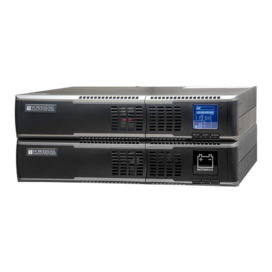
POWERVAR Sinergy III Rackmount / Tower User Instruction Manual
·
ACDEF700-11
·
ACDEF1000-11 1000 VA UPS
·
ACDEF1500-11 1500 VA UPS
·
ACDEF2000-11 2000 VA UPS
·
ACDEF3000-11 3000 VA UPS
· ACDEF2000-22 2000 VA UPS
· ACDEF3000-22 3000 VA UPS
This manual contains important instructions for the Sinergy III UPS and External Battery
Cabinets. Follow these instructions during the unpacking, installation, and maintenance of the
UPS and the External Battery Cabinet. If you have a problem with the UPS or the battery
cabinet, please refer to this manual before calling technical support.
POWERVAR
1450 South Lakeside Drive
Waukegan, IL 60085-8301
T (847) 596-7000
(800) 369-7179
F (847) 596-7100
www.powervar.com
A01-00040 Rev. E
Sinergy III 120 Volt UPS
700 VA UPS
· E024-12 External Battery Cabinet
· E036-12 External Battery Cabinet
· E048-12 External Battery Cabinet
· E072-12 External Battery Cabinet
Sinergy III 200-240 Volt UPS
· E048-12 External Battery Cabinet
· E072-12 External Battery Cabinet
Advertisement
Table of Contents


Need help?
Do you have a question about the ACDEF700-11 and is the answer not in the manual?
Questions and answers