Table of Contents

Subscribe to Our Youtube Channel
Related Manuals for Powervar 600-1000-1500-2000 VA


Summary of Contents for Powervar 600-1000-1500-2000 VA
-
Page 1: User Manual
User manual Ace Series Uninterruptible Power Supply 600-1000-1500-2000 VA UL-version POWERVAR Telephone 847-596-7000 1450 Lakeside Drive 847-596-7132 Waukegan, IL 60085 Website www.powervar.com ACE Series The ABCs of Power Conditioning... - Page 2 1 before installation and start-up of the UPS . All rights reserved. Reproduction in whole or in parts without the prior written consent of POWERVAR is prohibited. The illustrations and plans describing the equipment are intended as general reference only and are not necessarily complete in every detail.
-
Page 3: Table Of Contents
Contents Important safety instructions ................1 Save these instructions Safety rules Introduction ...................... 2 Introduction Intended use Transport / storage Warranty and RMA process Installation ......................3 Package contents Installation rules Installation procedure 3.3.1 Placement 3.3.2 Connecting interface devices 3.3.3 Charge the battery 3.3.4 Connect to utility supply... - Page 4 Computer interface USB port configuration Computer Network Security Recommendations Maintenance and Storage ................13 Maintenance Storage Conditions Extended Storage Conditions Battery…………………………………………………………………………………………………………………………………….…………………………………………………………………………………………………….. Battery Life Battery Rules Safety precautions Hot Swappable Battery Replacement Tower Procedure Appendix A: Troubleshooting………………………………………………………………………………………………………………………………………………………………………….. Appendix B: Specifications………………………………………………………………………………………………………………………………………………………….………………………… ACE Series –– Owner’’s Manual –– 03/17/09...
-
Page 5: Important Safety Instructions
The instructions in this manual pertain to ACE Series UPS models. While every care has been taken to ensure the completeness and accuracy of this manual, POWERVAR accepts no responsibility or liability for any loss or damage resulting from the use of the information contained in this document. -
Page 6: Introduction
2 - Introduction 2.1 Introduction The ACE Series is a line interactive uninterruptible power supply (UPS) which generates a true sine wave output, that protects your equipment from power anomalies, including complete power failures. The ACE Series UPS is based on microprocessor control. The line-interactive UPS provides pure, reliable AC power to the critical loads - protecting them from utility power blackout, swells, sags, surges and interference. -
Page 7: Transport / Storage
2.4 Warranty and RMA Process POWERVAR, operating through its authorized agents, warrants that the standard products will be free of defects in materials and workmanship for a period of twenty-four (24) months after the date of shipment, or such other period as may be specified. -
Page 8: Installation Rules
Computer interface connection is optional. The UPS works properly without a computer interface connection. Read the installation instructions provided with computer interface connection and follow accordingly. CAUTION Use only POWERVAR factory supplied or authorized UPS RS-232 communication cable! The RS-232 port requires a unique configured communication cable. NOTE Connect one (1) communication cable at a time. -
Page 9: Connect To Utility Supply
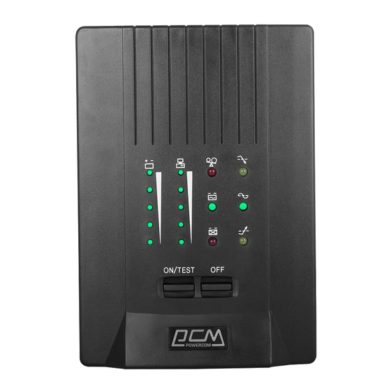
The UPS charges its battery whenever it is connected to utility power. Note: For best results, charge the battery for 4 (four) hours in the initial use. 3.3.4 Connect to utility supply 3.3.5 Check the site wiring fault indicator After connecting the load(s) and the UPS to utility power supply, check the site wiring fault indicator on the tower rear panel. The wiring fault indicator (RED) illuminates if the UPS is plugged into an improperly wired AC power outlet. - Page 10 OVERLOAD indicator (RED LED): The LED illuminates when the loads connected to the UPS exceed the UPS‘‘s capacity. BACK UP indicator (GREEN LED): The LED illuminates when the UPS is supplying battery power to the loads. REPLACE BATTERY indicator (RED LED): The LED illuminates when the UPS‘‘s battery is no longer useful and must be replaced.
-
Page 11: Back Panel
OFF button: Press the OFF button to turn OFF the UPS and the connected loads. Back panel 1500VA Tower shown TELELPHONE/MODEM connector Telecom transfer IN/OUT ports provide users to extend the RJ11 cable applications. CAUTION To reduce the risk of fire, use only No. 26AWG or larger RJ11 telecommunication line cord. OUTPUT POWER RECEPTACLES (NEMA 5-15R) AC INPUT POWER RECEPTACLE (NEMA 5-15P) ACE Series ––... - Page 12 SNMP adapter card provides real time UPS and power status information for the user. CAUTION Use only POWERVAR factory supplied or authorized SERIAL cable! NOTE Connect one (1) communication cable at a time. Do NOT connect (2) two communication cables simultaneously.
-
Page 13: Operation
Recharge the battery overnight (8-hours) and perform the self-test again. If the replace battery LED remains on, 847-596-7000 contact the POWERVAR UPS Service Center for help at Load Bar Graphic The 5-LED display indicator (on the front panel) shows the power drawn from the UPS by load. The display indicates the percentage of the UPS‘‘s rated capacity. -
Page 14: Operation ... ... ... ... ... ... ... ... ... ... ... ... ... ... ... ... ... ... ... ... ... ... ... ... ... ... ... ... ... ... ... ... ... ... ... ... ... ... ..... ... ... ... ... ... ... .... ... ... ... ... ... ... ... ... ... ... .....8
98SE/ME/2000/XP/2003 server for USB and LINUX. CAUTION Use only POWERVAR factory supplied or authorized RS-232 SERIAL cable! To reduce the risk of electric shock, disconnect the UPS from the input (utility) supply before installing a computer interface signal cable. Reconnect the input (utility) supply only after signaling interconnections have been made. -
Page 15: Computer Interface Usb Port Configuration
(Female View) UPS is supplied with a special RS-232 SERIAL cable (that is compatible with DB9 line) socket on the UPS rear panel. That port possesses several signals as explained below: Pin# Function Power Fail: Normally open status, will close when active OUTPUT Reference GND for pin 2 and 5 OUTPUT... -
Page 16: Computer Network Security Recommendations
(Female Type ““B”” connector Computer Network Security Recommendations When configuring devices such as PC servers, clients, gateways, and Intelligent Electronic Devices (including UPS products equipped with data communications capabilities) to interconnect over existing LAN's or other IT infrastructure, it is necessary to take appropriate precautions to ensure the secure and stable operation of these systems and the data that resides on them: For PC's running client and/or server applications, an antivirus solution should be installed and set to automatically update the program and virus definition files. -
Page 17: Battery Life
It does not contain CFCs (Chlorofluorocarbons) or HCFCs (Hydro chlorofluorocarbons). POWERVAR, in compliance with environment protection recommends to the User that the UPS equipment, at the end of its service life, must be recovered conforming to the local applicable regulations. -
Page 18: Hot Swappable Battery Replacement
600VA –– 2 batteries 1000VA –– 2 batteries 1500VA –– 3 batteries 2000VA –– 4 batteries Please call your local POWERVAR representative for pricing and availability. 9.5 Hot Swappable Battery Replacement Tower Procedure - Step 1. Remove front cover panel; pull out from top where finger grooves are located on each side. (See diagrams below) 600 &... - Page 19 600 & 1000VA 1500 & 2000VA Step 3. Remove inside battery cover plate. 600 & 1000VA Unscrew metal cover plate, Phillips-head screws. Put screws in a safe location for reconnection. (See diagrams below) 600 & 1000VA ACE Series –– Owner’’s Manual –– 03/17/09...
- Page 20 1500 & 2000VA Lift plate up, and then out toward front. (See diagram below) – 1500 & 2000VA Step 4. Carefully slide batteries out. 600 & 1000VA - Pull tabs attached to battery out toward front to remove batteries. (See diagram below) 600 &...
- Page 21 600 & 1000VA 1500 & 2000VA –– Disconnect Black wire. Disconnect Red wire. Continue to slide batteries out. (See diagrams below) 1500 & 2000VA Step 6. Remove batteries from UPS case. (See diagrams below) 600 & 1000VA ACE Series –– Owner’’s Manual –– 03/17/09...
- Page 22 1500VA 2000VA Step 7. Install New Batteries using same battery type and layout as shown in diagrams above. Step 8. Connect Jumper wire(s) to the + and –– of the new batteries as shown in diagrams above. Step 9. Before inserting the batteries into the unit: Connect the Black and Red Wire on the + terminal as shown in diagrams above.
- Page 23 Step 10. Slide the batteries into the UPS. Allow enough working space to make the final wiring connections in step below. Step 11. Final connections: 600 & 1000 VA: Connect the Black Wire as shown in diagram above. 1500 & 2000 VA: Connect the Red Wire as shown in diagrams above. Step 12.
-
Page 24: Appendix A: Troubleshooting
Non-fuse switch on the rear panel Press the Non-fuse switch to its "ON" position hasn't been opened Contact the POWERVAR UPS Service Center for help at Fault buzzer keeps sounding UPS has internal failure 847-596-7000 Alarm continues sounding... -
Page 25: Appendix B: Specifications
Appendix B: Specifications ACE Series Part Number: ACE 600 ACE 1000 ACE 1500 ACE 2000 Topology Line Interactive Output VA/Watts 600VA/360W 1000VA/600W 1500VA/900W 2000VA/1200W Output Power Factor Output voltage (Battery Mode) 120V, Pure sine wave at +/-5% of nominal, -10% of nominal after low battery warning Output Voltage (Utility Mode) 120V, +/-10% Output Frequency... - Page 26 10.4x21.7x13.4 1.75 ACE 1500 25.00 27.00 59.52 300x560x360 11.8x22.1x14.2 2.14 ACE 2000 30.00 32.00 70.55 300x560x360 11.8x22.1x14.2 2.14 Note: Characteristics are subject to change without prior notice. Please verify all details with POWERVAR. ACE Series –– Owner’’s Manual –– 03/17/09...
Need help?
Do you have a question about the 600-1000-1500-2000 VA and is the answer not in the manual?
Questions and answers