
Related Manuals for Mitsubishi Electric City Multi PQHY-P72


Summary of Contents for Mitsubishi Electric City Multi PQHY-P72
- Page 1 AIR CONDITIONERS CITY MULTI PQHY-P72, P96TGMU-A Models PQRY-P72, P96TGMU-A CMB-P104, P105, P106, P108, P1010, P1013, P1016NU-G CMB-P108, P1010, P1013, P1016NU-GA CMB-P104, P108NU-GB Service Handbook...
-
Page 2: Safety Precautions
Safety Precautions Before installing the unit, thoroughly read the following safety precautions. Observe these safety precautions for your safety. WARNING This symbol is intended to alert the user to the presence of important instructions that must be followed to avoid the risk of serious injury or death. - Page 3 WARNING Securely attach the terminal block cover (panel) to the After completing the service work, check for a gas leak. unit. If leaked refrigerant is exposed to a heat source, such as a If the terminal block cover (panel) is not installed properly, fan heater, stove, or electric grill, poisonous gases may be dust and/or water may infiltrate and pose a risk of electric produced.
- Page 4 Precautions for handling units for use with R410A CAUTION Do not use the existing refrigerant piping. Use a vacuum pump with a reverse-flow check valve. A large amount of chlorine that may be contained in the re- If a vacuum pump that is not equipped with a reverse-flow sidual refrigerant and refrigerating machine oil in the exist- check valve is used, the vacuum pump oil may flow into the ing piping may cause the refrigerating machine oil in the...
-
Page 5: Before Installing The Unit
Before installing the unit WARNING Do not install the unit where a gas leak may occur. When installing the unit in a hospital, take appropriate measures to reduce noise interference. If gaseous refrigerant leaks and piles up around the unit, it may be ignited. - Page 6 Before installing the unit (moving and reinstalling the unit) and performing electrical work WARNING When installing or relocating the unit, make sure that no substance other than the specified refrigerant (R410A) enters the refrigerant circuit. Any presence of foreign substance such as air can cause abnormal pressure rise or explosion.
- Page 7 Before the test run CAUTION Turn on the unit at least 12 hours before the test run. Do not operate the unit without panels and safety guards. Keep the unit turned on throughout the season. If the unit is turned off in the middle of a season, it may result in malfunc- Rotating, high-temperature, or high-voltage parts on the unit tions.
-
Page 8: Table Of Contents
CONTENTS Read Before Servicing [1] Read Before Servicing......................3 [2] Necessary Tools and Materials ....................4 [3] Piping Materials ........................5 [4] Storage of Piping ........................7 [5] Pipe Processing........................7 [6] Brazing ........................... 8 [7] Air Tightness Test........................9 [8] Vacuum Drying (Evacuation).................... - Page 9 CONTENTS IX Troubleshooting [1] Check Code Lists........................ 179 [2] Responding to Error Display on the Remote Controller............182 [3] Investigation of Transmission Wave Shape/Noise ............. 265 [4] Troubleshooting Principal Parts..................268 [5] Refrigerant Leak ......................... 298 [6] Servicing the BC controller ....................300 LED Monitor Display on the Heat Source Unit Board [1] How to Read the LED on the Service Monitor ..............
- Page 10 I Read Before Servicing [1] Read Before Servicing....................... 3 [2] Necessary Tools and Materials ..................4 [3] Piping Materials ......................... 5 [4] Storage of Piping ....................... 7 [5] Pipe Processing......................... 7 [6] Brazing..........................8 [7] Air Tightness Test......................9 [8] Vacuum Drying (Evacuation) ................... 10 [9] Refrigerant Charging .......................
- Page 11 - 2 -...
-
Page 12: Read Before Servicing
[ I Read Before Servicing ] I Read Before Servicing [1] Read Before Servicing 1. Check the type of refrigerant used in the system to be serviced. Refrigerant Type CITY MULTI WY/WR2: R410A 2. Check the symptoms exhibited by the unit to be serviced. Refer to this service handbook for symptoms relating to the refrigerant cycle. -
Page 13: Necessary Tools And Materials
[ I Read Before Servicing ] [2] Necessary Tools and Materials Prepare the following tools and materials necessary for installing and servicing the unit. Tools for use with R410A (Adaptability of tools that are for use with R22) 1. To be used exclusively with R410A (not to be used if used with R22) Tools/Materials Notes Gauge Manifold... -
Page 14: Piping Materials
[ I Read Before Servicing ] [3] Piping Materials Do not use the existing piping! New Piping Existing Piping 1. Copper pipe materials O-material (Annealed) Soft copper pipes (annealed copper pipes). They can easily be bent with hands. 1/2H-material, H-material (Drawn) Hard copper pipes (straight pipes). - Page 15 [ I Read Before Servicing ] 4. Thickness and refrigerant type indicated on the piping materials Ask the pipe manufacturer for the symbols indicated on the piping material for new refrigerant. 5. Flare processing (O-material (Annealed) only) The flare processing dimensions for the pipes that are used in the R410A system are larger than those in the R22 system. Flare processing dimensions (mm[in]) A dimension (mm[in]) Pipe size (mm[in])
-
Page 16: Storage Of Piping
[ I Read Before Servicing ] [4] Storage of Piping 1. Storage location Store the pipes to be used indoors. (Warehouse at site or owner's warehouse) If they are left outdoors, dust, dirt, or moisture may infiltrate and contaminate the pipe. 2. -
Page 17: Brazing
[ I Read Before Servicing ] [6] Brazing No changes have been made in the brazing procedures. Perform brazing with special care to keep foreign objects (such as oxide scale, water, and dust) out of the refrigerant system. Example: Inside the brazed connection Use of oxidized solder for brazing Use of non-oxidized solder for brazing 1. -
Page 18: Air Tightness Test
[ I Read Before Servicing ] [7] Air Tightness Test No changes have been made in the detection method. Note that a refrigerant leak detector for R22 will not detect an R410A leak. Halide torch R22 leakage detector 1. Items to be strictly observed Pressurize the equipment with nitrogen up to the design pressure (4.15MPa[601psi]), and then judge the equipment's air tightness, taking temperature variations into account. -
Page 19: Vacuum Drying (Evacuation)
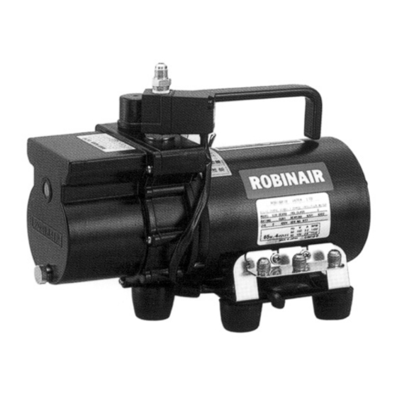
[ I Read Before Servicing ] [8] Vacuum Drying (Evacuation) (Photo1) 15010H (Photo2) 14010 Recommended vacuum gauge: ROBINAIR 14010 Thermistor Vacuum Gauge 1. Vacuum pump with a reverse-flow check valve (Photo1) To prevent the vacuum pump oil from flowing into the refrigerant circuit during power OFF or power failure, use a vacuum pump with a reverse-flow check valve. -
Page 20: Refrigerant Charging
[ I Read Before Servicing ] [9] Refrigerant Charging Cylinder with a siphon Cylinder without a siphon Cylin- Cylin- Cylinder color R410A is pink. Refrigerant charging in the liquid state Valve Valve liquid liquid 1. Reasons R410A is a pseudo-azeotropic HFC blend (boiling point R32=-52°C[-62°F], R125=-49°C[-52°F]) and can almost be han- dled the same way as a single refrigerant, such as R22. -
Page 21: Characteristics Of The Conventional And The New Refrigerants
[ I Read Before Servicing ] [11] Characteristics of the Conventional and the New Refrigerants 1. Chemical property As with R22, the new refrigerant (R410A) is low in toxicity and chemically stable nonflammable refrigerant. However, because the specific gravity of vapor refrigerant is greater than that of air, leaked refrigerant in a closed room will accumulate at the bottom of the room and may cause hypoxia. -
Page 22: Notes On Refrigerating Machine Oil
[ I Read Before Servicing ] [12] Notes on Refrigerating Machine Oil 1. Refrigerating machine oil in the HFC refrigerant system HFC type refrigerants use a refrigerating machine oil different from that used in the R22 system. Note that the ester oil used in the system has properties that are different from commercially available ester oil. Refrigerant Refrigerating machine oil Mineral oil... - Page 23 - 14 -...
-
Page 24: Restrictions
II Restrictions [1] Types and Maximum allowable Length of Cables ............17 [2] Switch Settings and Address Settings ................18 [3] Sample System Connection .................... 23 [4] An Example of a System to which an MA Remote Controller is connected ....24 [5] An Example of a System to which an M-NET Remote Controller is connected .... - Page 25 - 16 -...
-
Page 26: Types And Maximum Allowable Length Of Cables
[ II Restrictions ] II Restrictions [1] Types and Maximum allowable Length of Cables 1. Wiring work (1) Notes 1) Have all electrical work performed by an authorized electrician according to the local regulations and instructions in this manual. 2) Install the control cable at least 5cm[1-31/32"] away from the power supply cable to avoid noise interference. (Do not put the control cable and power supply cable in the same conduit tube.) 3) Provide class-D grounding on the outdoor (heat source) unit. -
Page 27: Switch Settings And Address Settings
[ II Restrictions ] 2) Remote controller wiring MA remote controller M-NET remote controller When the cable length ex- 10m [32ft] or less VCTF, VCTFK, CVV, CVS, ceeds 10m [32ft] Type VVR, VVF, VCT Shielded cable MVVS Number of 2-core cable 2-core cable Cable type cores... -
Page 28: Address Settings
[ II Restrictions ] 2. Address settings (1) Address settings table The need for address settings and the range of address setting depend on the configuration of the system. Unit or controller Address setting Setting method range dress setting Indoor Main/sub unit 0, 01 to 50 Assign the smallest address to the main indoor unit in the... - Page 29 [ II Restrictions ] (2) Power supply switch connector connection on the outdoor (heat source) unit (Factory setting: The male power supply switch connector is connected to CN41.) System configura- Connection to the Power supply unit for Group operation of Power supply switch con- tion system controller...
- Page 30 [ II Restrictions ] (6) Various start-stop controls (Indoor unit settings) Each indoor unit (or group of indoor units) can be controlled individually by setting SW 1-9 and 1-10. Setting (SW1) Operation of the indoor unit when the operation is Function resumed after the unit was stopped *2*3*4...
- Page 31 [ II Restrictions ] SW4-7:OFF (Compressor ON/OFF, NIGHT MODE) CN3D 1-3P Compressor ON/OFF CN3D 1-2P NIGHT MODE Open Open Short-circuit Short-circuit SW4-7:ON (STEP DEMAND) CN3D 1-2P Open Short-circuit Open 100% (not on the on-DEMAND control) CN3D 1-3P Short-circuit Note the following steps to be taken when using the STEP DEMAND (Example) When switching from 100% to 50% (Wrong) 100%...
-
Page 32: Sample System Connection
[ II Restrictions ] [3] Sample System Connection Examples of typical system connection are shown on pages [4] to [6]. (1) An example of a system to which an MA remote controller is connected O: Applicable, - : Non-applicable Address start Unit models up for indoor System... -
Page 33: An Example Of A System To Which An Ma Remote Controller Is Connected
[ II Restrictions ] [4] An Example of a System to which an MA Remote Controller is connected 1. System with one outdoor (heat source) unit (automatic address setup for both indoor and outdoor (heat source) units) Sample control wiring Interlock operation with the ventilation unit In the case of Y or WY... - Page 34 [ II Restrictions ] Wiring method/address setting method 1) Indoor/outdoor (heat source) transmission line Daisy-chain terminals M1 and M2 on the terminal block for indoor-outdoor (heat source) transmission line (TB3) on the outdoor (heat source) unit (OC), terminals M1 and M2 of the terminal block for indoor-outdoor (heat source) transmission line (TB02) on the BC controller (BC), and terminals M1 and M2 on the terminal block for indoor-out- door (heat source) transmission line (TB5) on each indoor unit (IC).
- Page 35 [ II Restrictions ] 2. An example of a system with one outdoor (heat source) unit to which 2 or more LOSSNAY units are connected (manual address setup for both indoor and outdoor (heat source) units) Sample control wiring Interlock operation with the ventilation unit In the case of Y or WY Group...
- Page 36 [ II Restrictions ] Wiring method 1) Indoor/outdoor (heat source) transmission line Same as [4] 1. [Shielded cable connection] Same as [4] 1. 2) Transmission line for centralized control No connection is required. 3) MA remote controller wiring Same as [4] 1. [When 2 remote controllers are connected to the system] Same as [4] 1.
- Page 37 [ II Restrictions ] Wiring method/address setting method Address Facto- Unit or controller setting Setting method Notes ry set- range ting Indoor Main unit 01 to 50 Assign the smallest address to Port number setting is unit the main unit in the group. required by an R2 or In an R2 or WR2 system with a WR2 system.
- Page 38 [ II Restrictions ] - 29 -...
- Page 39 [ II Restrictions ] 3. Group operation of units in a system with multiple outdoor (heat source) units Sample control wiring Interlock operation with the ventilation unit In the case of R2 or WR2 In the case of Y or WY CN41 CN40 CN41 CN40...
- Page 40 [ II Restrictions ] Wiring method 1) Indoor/outdoor (heat source) transmission line Daisy-chain terminals M1 and M2 on the terminal block for indoor-outdoor (heat source) transmission line (TB3) on the outdoor (heat source) unit (OC), terminals M1 and M2 of the terminal block for indoor-outdoor (heat source) transmission line (TB02) on the BC controller (BC and BS), and terminals M1 and M2 on the terminal block for in- door-outdoor (heat source) transmission line (TB5) on each indoor unit (IC).
- Page 41 [ II Restrictions ] Address setting method Address Facto- Unit or controller setting Setting method Notes ry set- range ting Indoor Main unit 01 to 50 Assign the smallest address to the Port number setting is re- unit main unit in the group. quired by an R2 or WR2 In an R2 or WR2 system with a sub system.
- Page 42 [ II Restrictions ] - 33 -...
- Page 43 [ II Restrictions ] 4. An example of a system in which a system controller is connected to the transmission line for central- ized control Sample control wiring Interlock operation with the ventilation unit In the case of R2 or WR2 In the case of Y or WY CN41 CN40 CN41 CN40...
- Page 44 [ II Restrictions ] Wiring method 1) Indoor/outdoor (heat source) transmission line Same as [4] 3. [Shielded cable connection] Same as [4] 1. 2) Transmission line for centralized control Daisy-chain terminals M1 and M2 on the terminal block for transmission line for centralized control (TB7) on each out- door (heat source) unit (OC).
- Page 45 [ II Restrictions ] Address setting method Address Facto- Unit or controller setting Setting method Notes ry set- range ting Indoor Main unit 01 to 50 Assign the smallest address to Port number setting is unit the main unit in the group. required by an R2 or In an R2 or WR2 system with a WR2 system.
- Page 46 [ II Restrictions ] - 37 -...
- Page 47 [ II Restrictions ] 5. An example of an R2 or WR2 system to which multiple BC controllers are connected (a system in which a system controller is connected to the transmission line for centralized control). Sample control wiring CN41 CN40 Replace SW2-1 OFF ON Group...
- Page 48 [ II Restrictions ] Wiring method 1) Indoor/outdoor (heat source) transmission line Daisy-chain terminals M1 and M2 on the terminal block for indoor-outdoor (heat source) transmission line (TB3) on the outdoor (heat source) unit (OC), terminals M1 and M2 of the terminal block for indoor-outdoor (heat source) trans- mission line (TB02) on the main BC controller (BC) and the sub BC controller (BS), and terminals M1 and M2 on the terminal block for indoor-outdoor (heat source) transmission line (TB5) on each indoor unit (IC).
- Page 49 [ II Restrictions ] Address setting method Address Facto- Unit or controller setting Setting method Notes ry set- range ting Indoor Main unit 01 to 50 Assign the smallest address to Port number setting is re- unit the main unit in the group. quired by an R2 or WR2 In an R2 or WR2 system with a system.
- Page 50 [ II Restrictions ] - 41 -...
- Page 51 [ II Restrictions ] 6. An example of a system in which a system controller is connected to the indoor-outdoor (heat source) transmission line (except LM adapter) Sample control wiring Interlock operation with the ventilation unit In the case of R2 or WR2 In the case of Y or WY CN41 CN40 CN41...
- Page 52 [ II Restrictions ] Wiring method 1) Indoor/outdoor (heat source) transmission line Daisy-chain terminals M1 and M2 on the terminal block for indoor-outdoor (heat source) transmission line (TB3) on the outdoor (heat source) unit (OC), terminals M1 and M2 of the terminal block for indoor-outdoor (heat source) transmission line (TB02) on the BC controller (BC and BS), terminals M1 and M2 on the terminal block for indoor-outdoor (heat source) transmission line (TB5) on each indoor unit (IC), and terminals M1 and M2 on the system controller.
- Page 53 [ II Restrictions ] Address setting method Address Facto- Unit or controller setting Setting method Notes ry set- range ting Indoor Main unit 01 to 50 Assign the smallest address to Port number setting is unit the main unit in the group. required by an R2 or In an R2 or WR2 system with a WR2 system.
- Page 54 [ II Restrictions ] - 45 -...
-
Page 55: An Example Of A System To Which An M-Net Remote Controller Is Connected
[ II Restrictions ] [5] An Example of a System to which an M-NET Remote Controller is connected 1. An example of a system in which a system controller is connected to the transmission line for central control Sample control wiring Interlock operation with In the case of Y or WY In the case of R2 or WR2... - Page 56 [ II Restrictions ] Wiring method 1) Indoor/outdoor (heat source) transmission line Same as [4] 3. [Shielded cable connection] Same as [4] 1. 2) Transmission line for centralized control Same as [4] 4. [Shielded cable connection] Same as [4] 3. 3) M-NET remote controller wiring Connect terminals M1 and M2 on the terminal block for indoor-outdoor (heat source) transmission line (TB5) on the indoor units (IC) to appropriate terminals on the terminal block on M-NET remote controller (RC).
- Page 57 [ II Restrictions ] Address setting method Address Facto- Unit or controller setting Setting method Notes ry set- range ting Indoor Main unit 01 to 50 Assign the smallest address to Enter the indoor unit unit the main unit in the group. group settings on the In an R2 or WR2 system with a system controller...
- Page 58 [ II Restrictions ] - 49 -...
-
Page 59: An Example Of A System To Which Both Ma Remote Controller And M-Net Remote Controller Are Connected
[ II Restrictions ] [6] An Example of a System to which both MA Remote Controller and M-NET Remote Controller are connected Sample control wiring In the case of R2 or WR2 In the case of Y or WY CN41 CN40 CN41 CN40 Replace Replace SW2-1 OFF ON... - Page 60 [ II Restrictions ] Wiring method/address setting method 1) Indoor/outdoor (heat source) transmission line Same as [4] 3. [Shielded cable connection] Same as [4] 1. 2) Transmission line for centralized control Same as [4] 4. [Shielded cable connection] Same as [4] 3. 3) MA remote controller wiring Same as [4] 1.
- Page 61 [ II Restrictions ] Wiring method/address setting method Address Facto- Unit or controller setting Setting method Notes ry set- range ting Opera- Indoor Main 01 to 50 After assigning an address to all Enter the indoor unit indoor units to be controlled group settings on the tion with unit...
-
Page 62: Restrictions On Pipe Length
[ II Restrictions ] [7] Restrictions on Pipe Length The refrigerant pipe from the outdoor (heat source) unit is branched at the pipe end, and each branch is then connected to an indoor unit. Flare connections are used for the pipes on the indoor units and for the liquid pipes on the outdoor (heat source) units. - Page 63 [ II Restrictions ] 1. PQHY (1) Line branching Heat source unit To downstream units Note : "Total sum of downstream unit model numbers" in the table is the sum of the model numbers of the units after point A in the figure. First branch Indoor Indoor...
- Page 64 [ II Restrictions ] (2) Header branching Heat source unit Note:Pipes from the header may not be re-branched. First branch Indoor Indoor Indoor Indoor Indoor Indoor Unit: m [ft] Allowable length of Operation Pipe sections pipes Length Total pipe length A+a+b+c+d+e+f 300 [984] or less Total pipe length (L) from the heat source unit to...
- Page 65 [ II Restrictions ] (3) A combination of line and header branching Heat source unit To downstream units Note : "Total sum of downstream unit model numbers" in the table is the sum of the model numbers of the units after point A in the figure. Branch header Note : Pipes from the header may not be First branch...
- Page 66 [ II Restrictions ] 2. PQRY (1) Line branching System that requires 16 BC controller ports or fewer <System with only the main BC controller or standard BC controller> Heat source unit 110 m [360ft] or less BC controller 40 m [131ft] or less Branch joint (For use with the Y series) CMY-Y102S-G...
- Page 67 [ II Restrictions ] (2) Line branching System that requires more than 16 BC controller ports or with multiple BC controllers <System with both main and sub BC controllers> <System that requires more than 16 BC controller ports> Heat source unit Indoor unit Indoor unit BC controller...
- Page 68 [ II Restrictions ] 3. Refrigerant pipe size (1) Between heat source unit and BC controller (Part A) Unit: mm [in] Heat source unit Operation PQRY-P72TGMU-A PQRY-P96TGMU-A Refrigerant High- pipe size pressure ø15.88 [5/8"] ø19.05 [3/4"] pipe Low- pressure ø19.05 [3/4"] ø22.2 [7/8"] pipe Connection...
- Page 69 [ II Restrictions ] (2) Between BC controller and indoor unit (Parts a, b, c, d, and e) Unit: mm [in] Indoor unit Operation 06,08,12,15,18 24,27,30,36,48 Refrigerant pipe Liquid ø6.35 [1/4"] ø9.52 [3/8"] size pipe ø12.7 [1/2"] ø15.88 [5/8"] ø19.05 [3/4"] ø22.2 [7/8"] pipe Connection to in-...
- Page 70 [ II Restrictions ] 4. Connecting the BC controller (1) Size of the pipe that fits the standard BC controller ports P72 and P96 models Connection: Brazed connection To heat source unit BC controller Reducer Branch joint (Model name:CMY-Y102S-G) Junction pipe kit (Standard (Optional accessory) (Model name:...
- Page 71 [ II Restrictions ] 1) To connect P06-P18 models of indoor units use the 2) To connect P72 or P96 models of indoor units (or when the reducer that is supplied with the BC controller. total capacity of indoor units exceeds P55), use a junction pipe kit (model name: CMY-R160J) and merge the two nozzles.
- Page 72 [ II Restrictions ] (2) Size of the pipe that fits the main BC controller ports P72 and P96 models Branch joint (Model name:CMY-Y102S-G) (Optional accessory Connection: brazed connection for use with the Y series To heat source unit of City Multi) Junction pipe kit Main BC controller (Model name:...
- Page 73 [ II Restrictions ] (3) Size of the pipe that fits the sub BC controller ports P72 and P96 models Connection: brazed connection Main BC controller Branch joint (Model name:CMY-Y102S-G) (Optional accessory Junction pipe kit Sub BC controller for use with the Y series (Model name: of City Multi) CMY-R160-J)
-
Page 74: Heat Source Unit / Bc Controller Components
III Heat Source Unit / BC Controller Components [1] Heat Source Unit Components and Refrigerant Circuit ........... 67 [2] Control Box of the Heat Source Unit................69 [3] Heat Source Unit Circuit Board..................70 [4] BC Controller (Under the panel) ..................73 [5] Control Box of the BC Controller .................. - Page 75 - 66 -...
-
Page 76: Heat Source Unit Components And Refrigerant Circuit
[ III Heat Source Unit / BC Controller Components ] III Heat Source Unit / BC Controller Components [1] Heat Source Unit Components and Refrigerant Circuit 1. PQHY-P72 and P96 models Sub box Control box Heat exchanger 4-way valve Check valve block... - Page 77 [ III Heat Source Unit / BC Controller Components ] 2. PQRY-P72 and P96 models Sub box Control box Heat exchanger 4-way valve Check valve block Solenoid valve (SV7a~7c) Solenoid valve block Fusible plug Compressor Accumulator - 68 -...
-
Page 78: Control Box Of The Heat Source Unit
[ III Heat Source Unit / BC Controller Components ] [2] Control Box of the Heat Source Unit 1. PQHY/PQRY-P72 and P96 models (1) Under the circuit board cover ACCT-U phase ACCT-W phase DCL ... Rear DCCT Smoothing capacitor(C1) Gateamp board Electromagnetic relay(52C) In-rush current protection(R1) Power circuit board... -
Page 79: Heat Source Unit Circuit Board
[ III Heat Source Unit / BC Controller Components ] [3] Heat Source Unit Circuit Board 1. Heat source MAIN board (1) PQHY/PQRY CNS1 CNS2 For indoor/outdoor (heat source) For centralized control CN40(with power supply transmission line (DC30V) system (DC30V) CNRS3B to centralized system) Serial communication input from... - Page 80 [ III Heat Source Unit / BC Controller Components ] 2. Heat source unit inverter board (1) PQHY/PQRY LED3 charge lamp CNDC2 DC bus voltage input 1 - 3 DC 280V CN15V2 Power output for IPM control 1 - 2 DC 15V 5 - 6 DC 15V 9 - 10 DC 15V 13 - 14 DC 15V...
-
Page 81: Relay Board
[ III Heat Source Unit / BC Controller Components ] 3. RELAY BOARD (1) PQHY/PQRY CN81 CN83 Solenoid valve output for 1 - 3 Operation-ON signal output unit control(208/230V) 5 - 7 Pump interlock input CNAC4 Power input 4 L1 phase 1 L2 phase CNOUT2 CNPW... -
Page 82: Bc Controller (Under The Panel)
[ III Heat Source Unit / BC Controller Components ] [4] BC Controller (Under the panel) 1. CMB-P NU-G (A) (1) Front Liquid pipe (Indoor unit side) Gas pipe (Indoor unit side) (2) Rear view <GA type> LEV2 TH16 LEV3 TH11 LEV1 Gas/Liquid separator... - Page 83 [ III Heat Source Unit / BC Controller Components ] 2. CMB-P NU-GB (1) Front Liquid pipe (Indoor unit side) Gas pipe (Indoor unit side) (2) Rear view TH22 LEV3a TH25 - 74 -...
-
Page 84: Control Box Of The Bc Controller
[ III Heat Source Unit / BC Controller Components ] [5] Control Box of the BC Controller 1. CMB-P1016NU-GA Transformer Terminal block for power supply Terminal block for transmission line Relay board BC controller board - 75 -... -
Page 85: Bc Controller Circuit Board
[ III Heat Source Unit / BC Controller Components ] [6] BC Controller Circuit Board 1. BC controller circuit board (BC board) - 76 -... - Page 86 [ III Heat Source Unit / BC Controller Components ] 2. RELAY BOARD (RELAY 4 board) 3. RELAY BOARD (RELAY 10 board) - 77 -...
- Page 87 - 78 -...
-
Page 88: Remote Controller
IV Remote Controller [1] Functions and Specifications of MA and ME Remote Controllers ........81 [2] Group Settings and Interlock Settings via the ME Remote Controller ......82 [3] Interlock Settings via the MA Remote Controller ............. 86 [4] Using the built-in Temperature Sensor on the Remote Controller........89 - 79 -... - Page 89 - 80 -...
-
Page 90: Functions And Specifications Of Ma And Me Remote Controllers
[ IV Remote Controller ] IV Remote Controller [1] Functions and Specifications of MA and ME Remote Controllers There are two types of remote controllers: M-NET (ME) remote controller, which is connected on the indoor-outdoor (heat source) transmission line, and MA remote controller, which is connected to each indoor unit. 1. -
Page 91: Group Settings And Interlock Settings Via The Me Remote Controller
[ IV Remote Controller ] [2] Group Settings and Interlock Settings via the ME Remote Controller 1. Group settings/interlock settings Make the following settings to perform a group operation of units that are connected to different outdoor (heat source) units or to manually set up the indoor/outdoor (heat source) unit address. - Page 92 [ IV Remote Controller ] Repeat steps in the previous page to interlock all the indoor units in a group with the LOSSNAY unit. (C) To return to the normal display When all the group settings and interlock settings are made, take the To go back to the normal display, To search for an address, following step to go back to the normal display.
- Page 93 [ IV Remote Controller ] (A) To delete group settings (B) To delete interlock settings <Successful completion of deletion> If deletion is successfully completed, will appear in the unit type display window. If the deletion fails, will (Displayed alternately) will be displayed in the room temperature display window. appear in the unit type display - If a transmission error occurs, the selected setting will not be window.
- Page 94 [ IV Remote Controller ] [Operation Procedures] 1. Press the [ON/OFF] button on the remote controller to bring the unit to a stop. The display will appear as shown in the previous page (Normal display). 2. Press buttons [CHECK] and [MODE] simultaneously for 2 seconds to go into the operation mode display selection mode under the remote controller function selection mode.
-
Page 95: Interlock Settings Via The Ma Remote Controller
[ IV Remote Controller ] [3] Interlock Settings via the MA Remote Controller 1. LOSSNAY interlock setting (Make this setting only when necessary.) Make this setting only when necessary. *When an upper controller is connected, make the settings on the upper controller. NOTE : To perform an interlocked operation with LOSSNAY units, interlock all the indoor units in the group with the LOSSNAY units. - Page 96 [ IV Remote Controller ] < 2. Search Procedures > To search for the LOSSNAY unit that is interlocked with a particular indoor unit, enter the address of the indoor unit into the remote controller that is connected to it. <Indoor unit address>...
- Page 97 [ IV Remote Controller ] 2. Remote controller function selection via the MA remote controller (1) Remote controller function The settings for the following remote controller functions can be changed in the remote controller function selection mode. Change the settings as necessary. Category 1 Category 2 Category 3 (Setting content)
-
Page 98: Using The Built-In Temperature Sensor On The Remote Controller
[ IV Remote Controller ] [Setting details] [4] -3. Mode selection (1) Remote controller main/sub setting [4] -1. Language selection The language that appears on the dot display can be selected from among Press the [ ON/OFF] button to change the following setting. the following. - Page 99 - 90 -...
-
Page 100: Electrical Wiring Diagram
V Electrical Wiring Diagram [1] Electrical Wiring Diagram of the Heat Source Unit ............93 [2] Electrical Wiring Diagram of the BC Controller..............94 - 91 -... - Page 101 - 92 -...
-
Page 102: Electrical Wiring Diagram Of The Heat Source Unit
[ V Electrical Wiring Diagram ] V Electrical Wiring Diagram [1] Electrical Wiring Diagram of the Heat Source Unit 1. Electrical wiring diagram of the heat source unit (1) PQHY/PQRY-P72 and P96 models - 93 -... -
Page 103: Electrical Wiring Diagram Of The Bc Controller
[ V Electrical Wiring Diagram ] [2] Electrical Wiring Diagram of the BC Controller (1) CMB-P104NU-G - 94 -... - Page 104 [ V Electrical Wiring Diagram ] (2) CMB-P105 and 106NU-G - 95 -...
- Page 105 [ V Electrical Wiring Diagram ] (3) CMB-P108 and 1010NU-G - 96 -...
- Page 106 [ V Electrical Wiring Diagram ] (4) CMB-P1013 and 1016NU-G - 97 -...
- Page 107 [ V Electrical Wiring Diagram ] (5) CMB-P108 and 1010NU-GA - 98 -...
- Page 108 [ V Electrical Wiring Diagram ] (6) CMB-P1013 and 1016NU-GA LEV3 LEV2 - 99 -...
- Page 109 [ V Electrical Wiring Diagram ] (7) CMB-P104NU-GB - 100 -...
- Page 110 [ V Electrical Wiring Diagram ] (8) CMB-P108NU-GB - 101 -...
- Page 111 - 102 -...
-
Page 112: Refrigerant Circuit
VI Refrigerant Circuit [1] Refrigerant Circuit Diagram ................... 105 [2] Principal Parts and Functions ..................109 - 103 -... - Page 113 - 104 -...
-
Page 114: Refrigerant Circuit Diagram
[ VI Refrigerant Circuit ] VI Refrigerant Circuit [1] Refrigerant Circuit Diagram 1. Heat source unit (1) PQHY-P72 and P96 models - 105 -... - Page 115 [ VI Refrigerant Circuit ] (2) PQRY-P72 and P96 models - 106 -...
- Page 116 [ VI Refrigerant Circuit ] 2. BC controller (1) CMB-P104, P105, P106, P108, P1010, P1013 and P1016NU-G Solenoid valves Block TH15 LEV3 TH12 HIC-B PS1 PS3 TH11 LEV1 TH16 Gas/Liquid Check valves Block Separator SVM1 (2) CMB-P108, P1010, P1013 and P1016NU-GA (main) Solenoid valves Block Gas pipe...
- Page 117 [ VI Refrigerant Circuit ] (3) CMB-P104 and P108NU-GB (sub) Solenoid valves Block TH25 TH22 LEV3a Check valves Block - 108 -...
-
Page 118: Principal Parts And Functions
[ VI Refrigerant Circuit ] [2] Principal Parts and Functions 1. Heat source unit (1) PQHY Part Symbols Check Notes Usage Specifications name (functions) method Compres- Adjusts the amount of circulating Low-pressure shell scroll (Comp1) refrigerant by adjusting the oper- compressor ating frequency based on the op- Wirewound resistance... - Page 119 [ VI Refrigerant Circuit ] Part Symbols Check Notes Usage Specifications name (functions) method Ther- TH11 1. Detects discharge air temper- Resis- = 7.465k mistor (Discharge) ature tance = 4057 25/120 2. Provides high-pressure pro- check tection 7.465 4057 0°C[32°F] :698kohm 10°C[50°F] :413kohm 20°C[68°F] :250kohm 30°C[86°F] :160kohm...
- Page 120 [ VI Refrigerant Circuit ] Part Symbols Check Notes Usage Specifications name (functions) method Linear ex- LEV1 Adjusts the amount of bypass DC12V Same with pansion (SC coil) flow from the liquid pipe on the Opening of a valve driven by a indoor LEV valve heat source unit during cooling...
- Page 121 [ VI Refrigerant Circuit ] (2) PQRY Symbols Part Check (func- Notes Usage Specifications name method tions) Compres- Adjusts the amount of circulating Low-pressure shell scroll (Comp1) refrigerant by adjusting the oper- compressor ating frequency based on the op- Wirewound resistance erating pressure data 10°C [50°F] : 0.155ohm 20°C [68°F] : 0.161ohm...
- Page 122 [ VI Refrigerant Circuit ] Symbols Part Check (func- Notes Usage Specifications name method tions) Ther- TH11 1. Detects discharge air temper- Resis- = 7.465k mistor (Dis- ature tance = 4057 25/120 charge) 2. Provides high-pressure pro- check tection 7.465 4057 0°C[32°F] : 698kohm 10°C[50°F] : 413kohm...
- Page 123 [ VI Refrigerant Circuit ] Symbols Part Check (func- Notes Usage Specifications name method tions) LInear ex- LEV2 Controls refrigerant flow of the in- Opening of a valve driven by a Same with pansion verter cooling heat exchanger stepping motor 0-480 pulses indoor LEV valve (Direct driven type)
-
Page 124: Indoor Unit
[ VI Refrigerant Circuit ] 2. Indoor unit Part Symbols Notes Usage Specifications Check method name (functions) Linear ex- 1. Adjusts superheat at the heat DC12V Refer to the sec- pansion exchanger outlet of the indoor Opening of a valve driven by tion "... - Page 125 [ VI Refrigerant Circuit ] 3. BC controller (1) G type Symbols Part Part name Usage Specifications Check method (functions) code Pressure 63HS1 1. Detects high pressure Pressure sensor (High pres- 2. LEV control 63HS 0~4.15 MPa [601psi] Vout 0.5~3.5V sure side) 1 2 3 0.071V/0.098 MPa [14psi]...
- Page 126 [ VI Refrigerant Circuit ] (2) GA type Symbols Part Part name Usage Specifications Check method (functions) code Pressure 63HS1 1. Detects high pressure Pressure sensor (High pres- 2. LEV control 63HS 0~4.15 MPa [601psi] Vout 0.5~3.5V sure side) 1 2 3 0.071V/0.098 MPa [14psi] Pressure [MPa] Con-...
- Page 127 [ VI Refrigerant Circuit ] (3) GB type Symbols Part Part name Usage Specifications Check method (functions) code Thermistor TH22 LEV control (Superheat) (Bypass = 15k outlet tem- = 3460 0/80 perature) R = 15 3460 TH25 LEV control (Superheat) 0°C[32°F] : 15kohm (Bypass in- 10°C[50°F] :9.7kohm...
-
Page 128: Control
VII Control [1] Functions and Factory Settings of the Dipswitches ............121 [2] Controlling the Heat Source Unit ................... 129 [3] Controlling BC Controller ....................142 [4] Operation Flow Chart..................... 143 - 119 -... - Page 129 - 120 -...
-
Page 130: Functions And Factory Settings Of The Dipswitches
[ VII Control ] VII Control [1] Functions and Factory Settings of the Dipswitches 1. Heat source unit (1) Main board [PQHY] Function according to switch setting Switch setting timing Switch Function Unit address setting Set to 00 or 51-100 with the dial switch Before power on For self-diagnosis/op- Refer to the LED monitor display on the... - Page 131 [ VII Control ] Function according to switch setting Switch setting timing Switch Function NIGHT MODE/Step NIGHT MODE Step DEMAND Before power on DEMAND mode LED Display "°C" "kg/cm G" "°F" "psi" When switching on the power Note1: All are set to OFF at factory shipment. Unless otherwise specified, set the switch to OFF where indicated by "-," which may be set to a certain setting for a reason.
- Page 132 [ VII Control ] [PQRY] Function according to switch setting Switch setting timing Switch Function Unit address setting Set to 00 or 51-100 with the dial switch Before power on For self-diagnosis/op- Refer to the LED monitor display on the 1-10 Anytime after power on eration monitoring...
- Page 133 [ VII Control ] Function according to switch setting Switch setting timing Switch Function LED Display "°C" "kg/cm G" "°F" "psi" When switching on the power Note1: All are set to OFF at factory shipment. Unless otherwise specified, set the switch to OFF where indicated by "-," which may be set to a certain setting for a reason.
- Page 134 [ VII Control ] 2. Function of the switch (Indoor unit) (1) Dipswitches [SW1,3] Function according to switch setting Switch setting timing Notes Switch Function Set to ON (built-in sensor on the remote controller) Room temperature Built-in sensor on Indoor unit inlet on All Fresh (PEFY-NMHU-E-F) model units detection position the remote controller...
- Page 135 [ VII Control ] [SW2] Model Capacity (model) code 1 2 3 4 5 6 1 2 3 4 5 6 1 2 3 4 5 6 1 2 3 4 5 6 1 2 3 4 5 6 1 2 3 4 5 6 setting Model Capacity (model) code...
- Page 136 [ VII Control ] (2) Slide switches Switch Switch Function Function according to switch setting setting tim- (PCFY-NGMU) Anytime af- Ceiling height Ceiling height ter power (High ceiling) 3.5m[11.45ft] setting (Standard-height ceiling) 2.8m[9.1ft] (Low ceiling) 2.3m[7.5ft] Ceiling height (PLFY-NAMU) Anytime af- P12-24 P30,36 setting...
- Page 137 [ VII Control ] 3. Function of the switch <Remote controller> ME remote controller (PAR-F27MEA-US-E) Set the address of the remote controller with the rotary switch. Rotary switch 10's digits 1's digits (left) (right) Remote controller unit Example: In case of address 108 Address setting range Setting method Main remote controller...
-
Page 138: Controlling The Heat Source Unit
[ VII Control ] [2] Controlling the Heat Source Unit -1- Initial Control <PQHY/PQRY> When the power is turned on, the initial processing of the microcomputer is given top priority. During the initial processing, control processing of the operation signal is suspended. The control processing is resumed after the initial processing is completed. - Page 139 [ VII Control ] -4- Compressor Frequency Control <PQHY/PQRY> Depending on the capacity required, the frequency of the compressor is controlled to keep constant evaporation temper- ature (0°C [32°F] = 0.71 MPa [103 psi]) during cooling operation, and condensing temperature (49°C [120°F] = 2.88 MPa [418 psi]) during heating operation.
- Page 140 [ VII Control ] -5- Refrigerant Recovery Control <PQHY> Recovery of refrigerant is performed during heating operation to prevent the refrigerant from accumulating inside the unit while it is stopped (unit in fan mode), or inside the indoor unit that is in cooling mode or in heating mode with thermo off. It is also performed during cooling operation to prevent an excessive amount of refrigerant from accumulating in the heat source heat exchanger.
- Page 141 [ VII Control ] -6- Refrigerant Recovery Control <PQRY> (1) Pattern A Recovery of refrigerant (Pattern A) is performed to prevent the refrigerant from accumulating in the BC controller. It is also performed during cooling operation to prevent an excessive amount of refrigerant from accumulating in the heat source unit heat exchanger.
- Page 142 [ VII Control ] -7- Heat Source Unit Heat Exchanger Capacity Control <PQHY> (1) Control method Heat exchanger capacity is controlled by the solenoid valve (SV4a-4d,7a-7c) to keep constant the evaporating temper- ature (0°C[32°F]=0.71MPa[103psi]) during cooling operation and condensing temperature (49°C[120°F]=2.88MPa[418psi]) during heating operation.
- Page 143 [ VII Control ] -8- Heat Source Unit Heat Exchanger Capacity Control <PQRY> (1) Control method Heat exchanger capacity is controlled by the solenoid valve (SV4a-4d,7a-7c) to keep constant the evaporating temper- ature (0°C[32°F]=0.71MPa[103psi]) during cooling operation and condensing temperature (49°C[120°F]=2.88MPa[418psi]) during heating operation.
- Page 144 [ VII Control ] Solenoid valve Operation mode SV4a SV4b SV4c SV4d SV7a SV7b SV7c Heating only Heating main *All solenoid valves are turned off while the unit is stopped. - 135 -...
- Page 145 [ VII Control ] -9- Subcool Coil Control (Linear Expansion Valve <LEV1>) <PQHY> The amount of super heat is controlled and kept constant based on the bypass outlet temperature (TH8) of subcool coil every 30 seconds. The degree of opening is controlled based on the subcool coil outlet/inlet temperature (TH5, TH7), high pressure (Pd), and discharge temperature.
- Page 146 [ VII Control ] -11- Method of Cooling the Control Box <PQHY/PQRY> The control box of the PQHY/PQRY models of units is equipped with a refrigerant evaporator to cool the heat that is gen- erated within the control box. It supplies refrigerant to the evaporator during inverter operation and also cools the inside of the unit and the control box by operating the cooling fan inside the control box.
- Page 147 [ VII Control ] -12- Control Method <PQRY> System configuration for the control system of the PQRY models shown below. Daisy-chained Non-polar 2-wire Data signal exchange non-polar 2-wire serial communication between system equipment method transmission line 16-bit CPU Calculation, processing microcomputer operation processing System control...
- Page 148 [ VII Control ] -13- Cooling/heating Circuit Control and General Function of System Equipment <PQRY> Operation Schematic diagram of refrigerant circuit Schematic diagram of refrigerating cycle Two-phase status Liquid 4-way valve Check valve Selector valve Low- Pressure pressure Low-pressure two-phase pipe Low-pressure Liquid...
- Page 149 [ VII Control ] -14- Operation Mode <PQHY> (1) Indoor unit operation mode The operation mode can be selected from the following 5 modes using the remote controller. Cooling mode Heating mode Dry mode Fan mode Stopping mode (2) Heat source unit operation mode Cooling mode All indoor units in operation are in cooling mode.
- Page 150 [ VII Control ] -15- Operation Mode <PQRY> (1) Indoor unit operation mode The operation mode can be selected from the following 6 modes using the remote controller. Cooling mode Heating mode Dry mode Automatic cooling/heating mode Fan mode Stopping mode (2) Heat source unit operation mode Cooling only mode All indoor units in operation are in cooling mode.
-
Page 151: Controlling Bc Controller
[ VII Control ] [3] Controlling BC Controller 1. Control of SV A, SV B, and SV A, SV B, and SV C turn on or off depending on the operation mode of the branch. Mode Cooling Heating Stopped Defrost Port 2. -
Page 152: Operation Flow Chart
[ VII Control ] [4] Operation Flow Chart 1. Mode determination flowchart <PQHY> (1) Indoor unit (cooling, heating, dry, fan mode) Start Normal operation Error Breaker Unit in the stopped state turned on From heat source unit Operation SW turned on 1. - Page 153 [ VII Control ] (2) Heat source unit (cooling and heating modes) Start Normal operation Error Breaker turned on Unit in the stopped state "HO" / "PLEASE WAIT" blinks on the remote controller *Note 1 Indoor units registered to the remote controller From indoor unit Operation...
- Page 154 [ VII Control ] 2. Operations in each mode <PQHY> (1) Cooling operation Cooling operation Normal operation During test run mode 4-way valve OFF Unit in the stopped state Indoor unit fan *Note 1 operation Test run mode Thermostat ON 3-minute restart prevention 1.
- Page 155 [ VII Control ] (2) Heating operation Normal operation Unit in the stopped state Heating operation During test run mode 4-way valve ON Test run mode Thermostat ON 3-minute restart prevention 1. Indoor unit fan operation at 1. Indoor unit fan control Very Low speed 2.
- Page 156 [ VII Control ] (3) Dry operation Dry operation Normal operation Thermostat ON 4-way valve OFF Unit in the stopped state Test run mode *Note 2 Thermostat ON Suction temperature 18 C[64 F] 1. Indoor unit fan stop 1. Heat source unit (compressor) intermittent operation 2.
- Page 157 [ VII Control ] 3. Mode determination flowchart <PQRY> (1) Indoor unit (cooling, heating, dry ,automatic cooling/heating and fan modes) Start Normal operation Error Breaker Stop turned on Operation SW turned on *Note 1 1. Protection function self-holding cancelled. 2. Indoor unit LEV fully closed. *Note 2 Remote controller Error mode...
- Page 158 [ VII Control ] (2) Heat source unit (cooling only, heating only, cooling main and heating main modes) Start Normal operation Error Breaker turned on Unit in the stopped state "HO" / "PLEASE WAIT" blinks *Note 1 on the remote controller Indoor units registered to the remote controller...
- Page 159 [ VII Control ] (3) BC controller (cooling only, heating only, cooling main and heating main modes) Start Normal operation Error Breaker turned on Unit in the stopped state Operation command 1. Determination of operation mode Protection function (Cooling only, Heating only, Mixture self-holding cancelled.
- Page 160 [ VII Control ] 4. Operations in each mode <PQRY> (1) Cooling operation Cooling operation Normal operation During test run mode 4-way valve OFF Unit in the stopped state Indoor unit fan *Note 1 operation Test run mode Thermostat 3-minute restart prevention 1.
- Page 161 [ VII Control ] (2) Heating operation Normal operation Heating operation Unit in the stopped state During test run mode 4-way valve ON Test run mode Thermostat 3-minute restart prevention 1. Indoor unit fan operation at 1. Indoor unit fan control Very Low speed 2.
- Page 162 [ VII Control ] (3) Dry operation Dry operation Normal operation Thermostat ON 4-way valve OFF Unit in the stopped state Test run mode *Note 2 Thermostat ON Suction temperature 18 C[64 F] *Note 1 1. Indoor unit fan stop 1.
- Page 163 - 154 -...
-
Page 164: Test Run Mode
VIII Test Run Mode [1] Items to be checked before a Test Run................. 157 [2] Test Run Method ......................158 [3] Operating Characteristic and Refrigerant Amount............159 [4] Adjusting the Refrigerant Amount.................. 160 [5] Refrigerant Amount Adjust Mode................... 164 [6] The following symptoms are normal................168 [7] Standard Operation Data (Reference Data) .............. - Page 165 - 156 -...
-
Page 166: Items To Be Checked Before A Test Run
[ VIII Test Run Mode ] VIII Test Run Mode [1] Items to be checked before a Test Run Check for refrigerant leak and loose cables and connectors. Measure the insulation resistance between the power supply terminal block and the ground with a 500V megger and make sure it reads at least 1.0Mohm. -
Page 167: Test Run Method
[ VIII Test Run Mode ] [2] Test Run Method The figure shows an MA deluxe remote controller. ON/OFF button Set Temperature buttons Down Fan Speed button TIME SUN MON TUE WED THU FRI SAT TIMER AFTER AFTER ERROR CODE FUNCTION FILTER WEEKLY... -
Page 168: Operating Characteristic And Refrigerant Amount
[ VIII Test Run Mode ] [3] Operating Characteristic and Refrigerant Amount It is important to have a clear understanding of the characteristics of refrigerant and the operating characteristics of air condi- tioners before attempting to adjust the refrigerant amount in a given system. 1. -
Page 169: Adjusting The Refrigerant Amount
[ VIII Test Run Mode ] [4] Adjusting the Refrigerant Amount 1. Symptoms Overcharging or undercharging of refrigerant can cause the following symptoms : Before attempting to adjust the amount of refrigerant in the system, thoroughly check the operating conditions of the system. Then, adjust the refrigerant amount by running the unit in the refrigerant amount adjust mode. - Page 170 [ VIII Test Run Mode ] 3. Amount of refrigerant to be added <PQHY> The amount of refrigerant that is shown in the table below is factory-charged to the heat source units. The amount necessary for extended pipe (field piping) is not included and must be added on site. Heat source unit model Amount of pre-charged re- frigerant in the heat source...
- Page 171 [ VIII Test Run Mode ] 4. Amount of refrigerant to be added <PQRY> The amount of refrigerant that is shown in the table below is factory-charged to the heat source units. The amount necessary for extended pipe (field piping) is not included and must be added on site. Heat source unit model Amount of pre-charged re- frigerant in the heat source...
- Page 172 [ VIII Test Run Mode ] (2) Example Heat source unit To downstream units Note : "Total sum of downstream unit model numbers" 110 m [360 ft] or less in the table is the sum of the model numbers of the units after point A in the figure.
-
Page 173: Refrigerant Amount Adjust Mode
[ VIII Test Run Mode ] [5] Refrigerant Amount Adjust Mode 1. Procedures <PQHY> Follow the procedures below to add or extract refrigerant as necessary depending on the operation mode. When the function switch switches (SW2-4) on the main board on the heat source unit are turned to ON, the unit will go into the refrigerant amount adjust mode. - Page 174 [ VIII Test Run Mode ] Start SW2-4 ON Put all indoor units in the test run mode *Refer to the previous page for *Notes 1-4 in the chart. and run the units in cooling mode. Has the initial start-up mode been completed? Has it been at least 30 minutes since...
- Page 175 [ VIII Test Run Mode ] 2. Procedures <PQRY> Follow the procedures below to add or extract refrigerant as necessary depending on the operation mode. When the function switch switches (SW2-4) on the main board on the heat source unit are turned to ON, the unit will go into the refrigerant amount adjust mode.
- Page 176 [ VIII Test Run Mode ] Start SW2-4 ON *Refer to the previous page for Note 1-4 in the chart . Put all indoor units in the test run mode and run the units in cooling mode. Has the initial start-up mode been completed? Has it been at least 30 minutes since start up?
-
Page 177: The Following Symptoms Are Normal
[ VIII Test Run Mode ] [6] The following symptoms are normal. Remote controller dis- Symptoms Cause play The indoor unit does not start "Cooling (heat- The unit cannot perform a heating (cooling) operation when other in- after starting cooling (heating) ing)"... -
Page 178: Standard Operation Data (Reference Data)
[ VIII Test Run Mode ] [7] Standard Operation Data (Reference Data) 1. PQHY <SI unit> (1) Cooling operation Heat source unit model Operation PQHY-P72TGMU-A PQHY-P96TGMU-A Power supply 208/230 208/230 Ambient tempera- Indoor 26.7/19.4 26.7/19.4 ture °C Heat source unit water tempera- °C 29.4 29.4... - Page 179 [ VIII Test Run Mode ] (2) Heating operation Heat source unit model Operation PQHY-P72TGMU-A PQHY-P96TGMU-A Power supply 208/230 208/230 Ambient tempera- Indoor 21.1/- 21.1/- ture °C Heat source unit water tempera- °C 21.1 21.1 ture Heat source unit water-flow rate 4.56 5.76 No.
- Page 180 [ VIII Test Run Mode ] 2. PQHY <US unit of measure> (1) Cooling operation Heat source unit model Operation PQHY-P72TGMU-A PQHY-P96TGMU-A Power supply 208/230 208/230 Ambient tempera- Indoor 80/67 80/67 ture °F Heat source unit water tempera- °F ture Heat source unit water-flow rate 1204 1521...
- Page 181 [ VIII Test Run Mode ] (2) Heating operation Heat source unit model Operation PQHY-P72TGMU-A PQHY-P96TGMU-A Power supply 208/230 208/230 Ambient tempera- Indoor 70/- 70/- ture °F Heat source unit water tempera- °F ture Heat source unit water-flow rate 1204 1521 No.
- Page 182 [ VIII Test Run Mode ] 3. PQRY <SI unit> (1) Cooling only operation Heat source unit model Model name of BC controller Operation PQRY-P72TGMU-A PQRY-P96TGMU-A CMB-P104NU-G CMB-P104NU-G Power supply 208/230 208/230 Ambient tempera- Indoor 26.7/19.4 26.7/19.4 ture °C Heat source unit water tem- °C 29.4 29.4...
- Page 183 [ VIII Test Run Mode ] (2) Heating only operation Heat source unit model Model name of BC controller Operation PQRY-P72TGMU-A PQRY-P96TGMU-A CMB-P104NU-G CMB-P104NU-G Power supply 208/230 208/230 Ambient tempera- Indoor 21.1/- 21.1/- ture °C Heat source unit water tem- °C 21.1 21.1...
- Page 184 [ VIII Test Run Mode ] 4. PQRY <US unit of measure> (1) Cooling only operation Heat source unit model Operation PQRY-P72TGMU-A PQRY-P96TGMU-A CMB-P104NU-G CMB-P104NU-G Power supply 208/230 208/230 Ambient tempera- Indoor 80/67 80/67 ture °F Heat source unit water tempera- °F ture Heat source unit water-flow rate...
- Page 185 [ VIII Test Run Mode ] (2) Heating only operation Heat source unit model Operation PQRY-P72TGMU-A PQRY-P96TGMU-A CMB-P104NU-G CMB-P104NU-G Power supply 208/230 208/230 Ambient tempera- Indoor 70/- 70/- ture °F Heat source unit water tempera- °F ture Heat source unit water-flow rate 1204 1521 No.
-
Page 186: Troubleshooting
IX Troubleshooting [1] Check Code Lists......................179 [2] Responding to Error Display on the Remote Controller..........182 [3] Investigation of Transmission Wave Shape/Noise ............265 [4] Troubleshooting Principal Parts..................268 [5] Refrigerant Leak ......................298 [6] Servicing the BC controller .................... 300 - 177 -... - Page 187 - 178 -...
-
Page 188: Check Code Lists
[ IX Troubleshooting ] IX Troubleshooting [1] Check Code Lists Searched unit Error Prelimi- (prelim- Error nary inary) Error code definition Notes Code error detail code code 0403 4300 Serial communication error 0900 Test run mode 1102 1202 Abnormal discharge air temperature 1301 Abnormal low pressure 1302... - Page 189 [ IX Troubleshooting ] Searched unit Error Prelimi- (prelim- Error nary inary) Error code definition Notes Code error detail code code Suction air temperature (TH21) Temperature sensor Return of OA processing 5101 1202 failure unit (TH4) Discharge air temperature (TH11) Indoor piping (TH22) Temperature sensor 5102...
- Page 190 [ IX Troubleshooting ] Searched unit Error Prelimi- (prelim- Error nary inary) Error code definition Notes Code error detail code code [115] ACCT sensor failure [116] DCCT sensor failure [117] ACCT sensor circuit failure 5301 4300 [118] DCCT sensor circuit failure [119] IPM open/Disconnected ACCT connector [120]...
-
Page 191: Responding To Error Display On The Remote Controller
[ IX Troubleshooting ] [2] Responding to Error Display on the Remote Controller -1- PQHY 1. Mechanical system Error definition and error Error Code Cause Check method and remedy detection method 0403 Serial commu- Serial communication er- (1) Faulty wiring Check the connection between the nication error ror between the main... - Page 192 [ IX Troubleshooting ] Error definition and error Error Code Cause Check method and remedy detection method 1102 Abnormal dis- 1. If the discharge tem- (1) Gas leak, gas shortage Refer to the page on refrigerant charge air tem- perature of 120°C amount evaluation.
- Page 193 [ IX Troubleshooting ] Error definition and error Error Code Cause Check method and remedy detection method 1301 Abnormal low When starting the com- (1) Inner pressure drop due to Refer to the section on troubleshoot- pressure pressor from Stop Mode a leakage.
- Page 194 [ IX Troubleshooting ] Error definition and error Error Code Cause Check method and remedy detection method 1302 Abnormal high (1) LEV failure on the indoor 1. If the pressure of Perform a heating operation and check pressure 1 3.87MPa [561psi] or unit the operation.
- Page 195 [ IX Troubleshooting ] Error definition and error Error Code Cause Check method and remedy detection method 1302 Abnormal high If the pressure of Refer to the page on the trouble- (1) Inner pressure drop due to a pressure 2 0.098MPa [14psi] or low- leakage.
- Page 196 [ IX Troubleshooting ] Error definition and error Error Code Cause Check method and remedy detection method 2134 Abnormal wa- 1. If an inlet water tem- (1) Heat source water pump ter tempera- perature of 5°C [41 failure ture °F] or below, or (2) Problems with the cooling 50°C[122 °F] or above tower or heating device...
- Page 197 [ IX Troubleshooting ] Error definition and error Error Code Cause Check method and remedy detection method 2135 Water heat ex- 1. If the following condi- (1) Heat source water pump changer freez- tions are met (1st failure time) during the oper- (2) Problems with the heating ation, the heat source device...
- Page 198 [ IX Troubleshooting ] Error definition and error Error Code Cause Check method and remedy detection method 2500 Water leakage Detection of water im- (1) Water leakage due to de- 1) Check the error history. Rate of occurrence mersion of drain sensor terioration of the elements *If the same problem is experi- while the drain pump is...
- Page 199 [ IX Troubleshooting ] Error definition and error Error Code Cause Check method and remedy detection method 2502 Drain pump When the drain sensor (1) Drain pump malfunction 1) Check for drain pump malfunc- failure detects water or its tip be- (2) Clogged drain pump intake tion (The error...
- Page 200 [ IX Troubleshooting ] Error definition and error Error Code Cause Check method and remedy detection method 2503 Drain sensor When a short or an open (1) Thermistor failure Check the thermistor resistance. failure is detected during opera- (2) Connector contact failure 0°C [32°F] : 6.0 kohm tion (cannot be detected (loose connector)
- Page 201 [ IX Troubleshooting ] Error definition and error Error Code Cause Check method and remedy detection method 4115 Power supply The frequency cannot be (1) Power supply error Check the voltage of the power sup- sync signal ab- determined when the ply terminal block (TB1).
- Page 202 [ IX Troubleshooting ] Error definition and error Error Code Cause Check method and remedy detection method 4220 Bus voltage If Vdc 150V or less is de- (1) Power supply environment Check whether the unit makes an instanta- neous stop when the detection result is ab- drop tected during Inverter op- normal or a power failure occurs.
- Page 203 [ IX Troubleshooting ] Error definition and error Error Code Cause Check method and remedy detection method 4220 Logic error If only the H/W error logic (1) External noise Refer to 9.[4].-7-.(2) [1] and replace (Detail code circuit operates, and no (2) Compressor INV board the G/A board.
- Page 204 [ IX Troubleshooting ] Error definition and error Error Code Cause Check method and remedy detection method 4240 Overload pro- When the greater output (1) Short cycle of the air pas- Check that the waste heat from the tection current (Iac) than the sage heat source unit fan is not short cy- Imax (Arms), or THHS of...
- Page 205 [ IX Troubleshooting ] Error definition and error Error Code Cause Check method and remedy detection method 4250 IPM error When an error signal of (1) Inverter output related Same as 4230 error (Detail code IPM is detected (2) Same as 4230 error 101) ACCT overcur- When overcurrent break...
- Page 206 [ IX Troubleshooting ] Temperature sensor failure (indoor unit) Error definition and error Error Code Cause Check method and remedy detection method 5101 Air inlet If a short or an open is (1) Thermistor failure Check the thermistor resistor. detected during thermo- (2) Connector contact failure 0°C [32°F]: 15 kohm 5102...
- Page 207 [ IX Troubleshooting ] Temperature sensor failure (heat source unit) Error definition and error Error Code Cause Check method and remedy detection method 5101 Discharge 1. When a short (high (1) Thermistor failure Check thermistor resistance. (TH11) temperature intake) or an open (low tempera- 5105 Piping...
- Page 208 [ IX Troubleshooting ] Error definition and error Error Code Cause Check method and remedy detection method 5110 Heat sink fail- When a short or an open (1) THHS sensor failure Check for short circuit in THHS sen- of THHS is detected just sor.
- Page 209 [ IX Troubleshooting ] Error definition and error Error Code Cause Check method and remedy detection method 5301 ACCT sensor When an error value is (1) Compressor INV board Refer to 9 [4]-7-(2) [1] circuit failure detected with the ACCT failure "Check the compressor INV board (Detail code...
- Page 210 [ IX Troubleshooting ] 2. Transmission error Error Error definition and error detec- Cause Check method and remedy Code tion method 6201 Remote controller board failure Remote controller failure Replace the remote controller. An error occurs when the data cannot be read normally from the nonvolatile memory built in on the remote controller.
- Page 211 [ IX Troubleshooting ] Error Error definition and error detec- Check method and remedy Code tion method 6602 Transmission processor hard- (1) When the wiring work of or the polarity of either the indoor or heat source ware error transmission line is performed or is changed while the power is on, the trans- mitted data will collide, the wave shape will be changed, and an error will be Although "0"...
- Page 212 [ IX Troubleshooting ] Error Error definition and error detec- Cause Check method and remedy Code tion method 6603 Transmission circuit bus-busy (1) The transmission processor No noise indicates that the error source cannot be transmitted as the controller is a failure. 1.
- Page 213 [ IX Troubleshooting ] (1) System with one heat source unit Error Code Error definition and error detection method 6607 No ACK abnormality The error is detected when no acknowledgement (ACK signal) is received after the transmission. (eg. When the data is transmitted six times in a row with 30 seconds interval, the error is detected on the transmission side.) Note: The address/attribute appeared on the display on the remote controller indicates the controller which did not provide the response (ACK).
- Page 214 [ IX Troubleshooting ] (2) Grouping of units in a system with multiple heat source units Error Code Error definition and error detection method 6607 No ACK abnormality The error is detected when no acknowledgement (ACK signal) is received after the (Contin- transmission.
- Page 215 [ IX Troubleshooting ] (2) Grouping of units in a system with multiple heat source units Error Code Error definition and error detection method 6607 No ACK abnormality The error is detected when no acknowledgement (ACK signal) is received after the (Contin- transmission.
- Page 216 [ IX Troubleshooting ] (3) System connected to the system controllers (MELANS) Error Code Error definition and error detection method 6607 No ACK abnormality The error is detected when no acknowledgement (ACK signal) is received after the (Contin- transmission. (eg. When the data is transmitted six times in a row with 30 seconds ued) interval, the error is detected on the transmission side.) Note: The address/attribute appeared on the display on the remote controller...
- Page 217 [ IX Troubleshooting ] (3) System connected to the system controllers (MELANS) Error Code Error definition and error detection method 6607 No ACK abnormality The error is detected when no acknowledgement (ACK signal) is received after the (Contin- transmission. (eg. When the data is transmitted six times in a row with 30 seconds ued) interval, the error is detected on the transmission side.) Note: The address/attribute appeared on the display on the remote controller...
- Page 218 [ IX Troubleshooting ] (3) System connected to the system controllers (MELANS) Error Code Error definition and error detection method 6607 No ACK abnormality The error is detected when no acknowledgement (ACK signal) is received after the (Contin- transmission. (eg. When the data is transmitted six times in a row with 30 seconds ued) interval, the error is detected on the transmission side.) Note: The address/attribute appeared on the display on the remote controller...
- Page 219 [ IX Troubleshooting ] (4) Errors that are not limited to a particular system Error Code Error definition and error detection method 6607 No ACK abnormality The error is detected when no acknowledgement (ACK signal) is received after the (Contin- transmission.
- Page 220 [ IX Troubleshooting ] Error Error definition and error detec- Cause Check method and remedy Code tion method 6608 No response (1) The transmission line work is 1) When an error occurs at commission- When no response command performed while the power is on, is returned although acknowl- the transmitted data will collide, Turn off the power source of the heat...
- Page 221 [ IX Troubleshooting ] Error Error definition and error detec- Cause Check method and remedy Code tion method 6831 MA communication error or no (1) Contact failure of the remote 1) Check for disconnected or loose reception error controller lines of MA remote transmission lines for the indoor units Communication between the controller or the indoor unit.
- Page 222 [ IX Troubleshooting ] 3. System error Error Error definition and error Error source Cause Check method and remedy Code detection method 7100 Heat source Total capacity error The model total of indoor units 1) Check the model total (capacity unit in the system with one heat code total) of indoor units con-...
- Page 223 [ IX Troubleshooting ] Error Error definition and error Error source Cause Check method and remedy Code detection method 7102 Heat source Error in the number of (1) Number of indoor units 1) Check whether the number of unit connected units connected to the heat units connected to the heat source terminal block...
- Page 224 [ IX Troubleshooting ] Error Error definition and error Error source Cause Check method and remedy Code detection method 7110 Heat source Unset unit connection When all power sources are 1) Check whether the power unit information error turned off after the start-up of source of the transmission is the unit has completed normal- turned on.
-
Page 225: Mechanical System
[ IX Troubleshooting ] -2- PQRY 1. Mechanical system Error definition and error Error Code Cause Check method and remedy detection method 0403 Serial commu- Serial communication er- (1) Faulty wiring Check the connection between the nication error ror between the main Main board connector CNRS3B and board and the INV board compressor INV board connector... - Page 226 [ IX Troubleshooting ] Error definition and error Error Code Cause Check method and remedy detection method 1102 Abnormal dis- 1. If the discharge tem- (1) Gas leak, gas shortage Refer to the page on refrigerant charge air tem- perature of 120 amount evaluation.
- Page 227 [ IX Troubleshooting ] Error definition and error Error Code Cause Check method and remedy detection method 1301 Abnormal low When starting the com- (1) Inner pressure drop due to Refer to the section on troubleshoot- pressure pressor from Stop Mode a leakage.
- Page 228 [ IX Troubleshooting ] Error definition and error Error Code Cause Check method and remedy detection method 1302 Abnormal high (1) LEV failure on the indoor Perform a heating operation and 1. If the pressure of pressure 1 3.87MPa[561psi] or unit check the operation.
- Page 229 [ IX Troubleshooting ] Error definition and error Error Code Cause Check method and remedy detection method 1302 Abnormal high If the pressure of Refer to the page on the trouble- (1) Inner pressure drop due to a pressure 2 0.098MPa[14psi] or low- leakage.
- Page 230 [ IX Troubleshooting ] Error definition and error Error Code Cause Check method and remedy detection method 2134 Abnormal wa- 1. If an inlet water tem- (1) Heat source water pump ter tempera- perature of 5°C [41 failure ture °F] or below, or (2) Problems with the cooling 50°C[122 °F] or above tower or heating device...
- Page 231 [ IX Troubleshooting ] Error definition and error Error Code Cause Check method and remedy detection method 2135 Water heat ex- 1. If the following condi- (1) Heat source water pump changer freez- tions are met during failure (1st time) the opera- (2) Problems with the heating tion, the heat source device...
- Page 232 [ IX Troubleshooting ] Error definition and error Error Code Cause Check method and remedy detection method 2500 Water leakage Detection of water im- (1) Water leakage due to de- 1) Check the error history. Rate of occurrence mersion of drain sensor terioration of the elements *If the same problem is experi- while the drain pump is...
- Page 233 [ IX Troubleshooting ] Error definition and error Error Code Cause Check method and remedy detection method 2502 Drain pump When the drain sensor (1) Drain pump malfunction 1) Check for drain pump malfunction Check whether there is water in the failure detects water or its tip be- (2) Clogged drain pump intake...
- Page 234 [ IX Troubleshooting ] Error definition and error Error Code Cause Check method and remedy detection method 2503 Drain sensor When a short or an open (1) Thermistor failure Check the thermistor resistance. failure is detected during opera- (2) Connector contact failure 0°C [32°F] : 6.0 kohm tion (cannot be detected (loose connector)
- Page 235 [ IX Troubleshooting ] Error definition and error Error Code Cause Check method and remedy detection method 4115 Power supply The frequency cannot be (1) Power supply error Check the voltage of the power sup- sync signal ab- determined when the ply terminal block (TB1).
- Page 236 [ IX Troubleshooting ] Error definition and error Error Code Cause Check method and remedy detection method 4220 Bus voltage If Vdc 150V or less is de- (1) Power supply environment Check whether the unit makes an instanta- neous stop when the detection result is ab- drop tected during Inverter op- normal or a power failure occurs.
- Page 237 [ IX Troubleshooting ] Error definition and error Error Code Cause Check method and remedy detection method 4220 Logic error If only the H/W error logic (1) External noise Refer to 9 [4] -7- (2) [1] (Detail code circuit operates, and no (2) Compressor INV board Replace the G/A board.
- Page 238 [ IX Troubleshooting ] Error definition and error Error Code Cause Check method and remedy detection method 4240 Overload pro- When the greater output (1) Short cycle of the air pas- Check that the waste heat from the tection current (Iac) than the sage heat source unit fan is not short cy- Imax (Arms), or THHS of...
- Page 239 [ IX Troubleshooting ] Error definition and error Error Code Cause Check method and remedy detection method 4250 IPM error When an error signal of (1) Inverter output related Same as 4230 error (Detail code IPM is detected (2) Same as 4230 error 101) ACCT overcur- When overcurrent break...
- Page 240 [ IX Troubleshooting ] Temperature sensor failure (indoor unit) Error definition and error Error Code Cause Check method and remedy detection method 5101 Air inlet If a short or an open is (1) Thermistor failure Check the thermistor resistor. detected during thermo- (2) Connector contact failure 0°C [32°F] : 15 kohm 5102...
- Page 241 [ IX Troubleshooting ] Temperature sensor failure (heat source unit) Error definition and error Error Code Cause Check method and remedy detection method 5101 Discharge 1. When a short (high (1) Thermistor failure Check thermistor resistance. (TH11) temperature intake) or an open (low tempera- 5106 Inlet water...
- Page 242 [ IX Troubleshooting ] Error definition and error Error Code Cause Check method and remedy detection method 5110 Heat sink fail- When a short or an open (1) THHS sensor failure Check for short circuit in THHS sen- of THHS is detected just sor.
- Page 243 [ IX Troubleshooting ] High pressure sensor failure (BC controller) Error definition and error Error Code Cause Check method and remedy detection method 5201 Liquid side When the pressure of (1) High pressure sensor fail- Refer to the page on the troubleshooting of the high pressure sensor.(9.[4].-1-) 4.06MPa [589psi] or more is detected by the pressure...
- Page 244 [ IX Troubleshooting ] Error definition and error Error Code Cause Check method and remedy detection method 5301 ACCT sensor When an error value is (1) Compressor INV board Refer to 9. [4].-7-.(2). [1] "Check the com- pressor INV board error detection circuit" circuit failure detected with the ACCT failure...
- Page 245 [ IX Troubleshooting ] 2. Transmission error Error Error definition and error detec- Cause Check method and remedy Code tion method 6201 Remote controller board failure Remote controller failure Replace the remote controller. An error occurs when the data cannot be read normally from the nonvolatile memory built in on the remote controller.
- Page 246 [ IX Troubleshooting ] Error Error definition and error detec- Check method and remedy Code tion method 6602 Transmission processor hard- (1) When the wiring work of or the polarity of either the indoor or heat source ware error transmission line is performed or is changed while the power is on, the trans- mitted data will collide, the wave shape will be changed, and an error will be Although "0"...
- Page 247 [ IX Troubleshooting ] Error Error definition and error detec- Cause Check method and remedy Code tion method 6603 Transmission circuit bus-busy (1) The transmission processor Check transmission wave shape/noise on cannot be transmitted as the trans-mission line by following <Investiga- 1.
- Page 248 [ IX Troubleshooting ] (1) System with one heat source unit Error Code Error definition and error detection method 6607 No ACK abnormality The error is detected when no acknowledgement (ACK signal) is received after the transmission. (eg. When the data is transmitted six times in a row with 30 seconds interval, the error is detected on the transmission side.) Note: The address/attribute appeared on the display on the remote controller indicates the controller which did not provide the response (ACK).
- Page 249 [ IX Troubleshooting ] (2) Grouping of units in a system with multiple heat source units Error Code Error definition and error detection method 6607 No ACK abnormality The error is detected when no acknowledgement (ACK signal) is received after the (Contin- transmission.
- Page 250 [ IX Troubleshooting ] (2) Grouping of units in a system with multiple heat source units Error Code Error definition and error detection method 6607 No ACK abnormality The error is detected when no acknowledgement (ACK signal) is received after the (Contin- transmission.
- Page 251 [ IX Troubleshooting ] (3) System connected to the system controllers (MELANS) Error Code Error definition and error detection method 6607 No ACK abnormality The error is detected when no acknowledgement (ACK signal) is received after the (Contin- transmission. (eg. When the data is transmitted six times in a row with 30 seconds ued) interval, the error is detected on the transmission side.) Note: The address/attribute appeared on the display on the remote controller...
- Page 252 [ IX Troubleshooting ] (3) System connected to the system controllers (MELANS) Error Code Error definition and error detection method 6607 No ACK abnormality The error is detected when no acknowledgement (ACK signal) is received after the (Contin- transmission. (eg. When the data is transmitted six times in a row with 30 seconds ued) interval, the error is detected on the transmission side.) Note: The address/attribute appeared on the display on the remote controller...
- Page 253 [ IX Troubleshooting ] (3) System connected to the system controllers (MELANS) Error Code Error definition and error detection method 6607 No ACK abnormality The error is detected when no acknowledgement (ACK signal) is received after the (Contin- transmission. (eg. When the data is transmitted six times in a row with 30 seconds ued) interval, the error is detected on the transmission side.) Note: The address/attribute appeared on the display on the remote controller...
- Page 254 [ IX Troubleshooting ] (4) Errors that are not limited to a particular system Error Code Error definition and error detection method 6607 No ACK abnormality The error is detected when no acknowledgement (ACK signal) is received after the (Contin- transmission.
- Page 255 [ IX Troubleshooting ] Error Error definition and error detec- Cause Check method and remedy Code tion method 6608 No response (1) The transmission line work of 1) When an error occurs at commission- When no response command one of the indoor unit, heat is returned although acknowl- source unit, or the BC controller Turn off the power sources of the heat...
- Page 256 [ IX Troubleshooting ] Error Error definition and error detec- Cause Check method and remedy Code tion method 6831 MA communication error or no (1) Contact failure of the remote 1) Check for disconnected or loose reception error controller lines of MA remote transmission lines for the indoor units Communication between the controller or the indoor unit.
- Page 257 [ IX Troubleshooting ] 3. System error Error Error definition and error Error source Cause Check method and remedy Code detection method 7100 Heat source Total capacity error The model total of indoor units 1) Check the model total (capacity unit in the system with one heat code total) of indoor units con-...
- Page 258 [ IX Troubleshooting ] Error Error definition and error Error source Cause Check method and remedy Code detection method 7102 Heat source Error in the number of (1) Number of indoor units 1) Check whether the number of unit connected units connected to the heat units connected to the heat source terminal block...
- Page 259 [ IX Troubleshooting ] Error Error definition and error Error source Cause Check method and remedy Code detection method 7106 Attribute setting error MA remote controller intended To operate the OA processing unit for use with indoor units, such using remote controllers for indoor as an MA remote controller, is units, such as MA remote controller, connected to the OA process-...
- Page 260 [ IX Troubleshooting ] Error Error source Check method and remedy Code 7107 BC controller For the address of the BC controller (Sub), is 50 added to Change the BC Is there a BC the smallest indoor unit address, controller controller (Sub)? which is connected to the (Sub) address.
- Page 261 [ IX Troubleshooting ] 4. Troubleshooting according to the remote controller malfunction or the external input error <PQHY/PQRY> (1) In the case of MA remote controller Phenomena Cause Check method and remedy Even if the operation button on 1. The power is not supplied to the (1) Measure voltages of the MA remote the remote controller is indoor unit.
- Page 262 [ IX Troubleshooting ] Phenomena Cause Check method and remedy When the remote controller op- 1. The power for the M-NET trans- When 2. and 3. apply, check code 7102 eration SW is turned on, the mission line is not supplied from will be displayed on the self-diagnosis operation status briefly ap- the heat source unit.
- Page 263 [ IX Troubleshooting ] Phenomena Cause "HO" or "PLEASE WAIT" dis- 1. The power for the M-NET transmission line is not supplied from the heat source play on the remote controller unit. does not disappear, and no op- 2. Short-circuited transmission line eration is performed even if the 3.
- Page 264 [ IX Troubleshooting ] Flow chart Even if the operation button on the remote controller is pressed, the indoor and the heat source units do not start running. - 255 -...
- Page 265 [ IX Troubleshooting ] (2) In case of M-NET remote controller Phenomena Cause Check method and remedy Even if the operation button on 1. The power for the M-NET trans- Check voltage of the transmission terminal the remote controller is mission line is not supplied from block for of the M-NET remote controller.
- Page 266 [ IX Troubleshooting ] Phenomena Cause Check method and remedy When the remote controller op- 1. The power is not supplied to the indoor unit. eration SW is turned on, a tem- The main power of the indoor unit (AC208/230V) is not on. porary operation display is The connector on the indoor unit board has come off.
- Page 267 [ IX Troubleshooting ] Phenomena Cause "HO" or "PLEASE WAIT" dis- Without using MELANS 1. Heat source unit address is set to "00" play on the remote controller 2. A wrong address is set. does not disappear, and no op- A wrong address is set to the indoor unit to be coupled with the remote controller.
- Page 268 [ IX Troubleshooting ] Phenomena Cause "88" appears on the remote An error occurs when the ad- (1) Confirm the address of unit to be cou- controller when the address is dress is registered or confirmed. pled. registered or confirmed. (common) (2) Check the connection of transmission 1.
- Page 269 [ IX Troubleshooting ] (3) Both for MA remote controller and M-NET remote controller Phenomena Cause Check method and remedy Although cooling operation 1. Compressor frequency does not (1) Check pressure difference between the starts with the normal remote rise sufficiently. detected pressure by the pressure sen- controller display, the capacity Faulty detection of pressure...
- Page 270 [ IX Troubleshooting ] Phenomena Cause Check method and remedy Although cooling operation 3. Long piping length Confirm that the characteristic of capacity starts with the normal remote The cooling capacity varies great- drop due to piping length. controller display, the capacity ly depending on the pressure The piping pressure loss can be assumed is not enough.
- Page 271 [ IX Troubleshooting ] Phenomena Cause Check method and remedy Although heating operation 1. Compressor frequency does not (1) Check pressure difference between the starts with the normal remote rise sufficiently. detected pressure by the pressure sen- controller display, the capacity Faulty detection of pressure sor and the actual pressure with self-di- is not enough.
- Page 272 [ IX Troubleshooting ] Phenomena Cause Check method and remedy Although heating operation 4. Insulation failure of the refrigerant starts with the normal remote piping controller display, the capacity 5. Long piping length Confirm that the characteristic of capacity is not enough. Excessively long piping on the drop due to piping length.
- Page 273 [ IX Troubleshooting ] Phenomena Cause Check method and remedy Heat source unit stops at times The first stop is not considered as an (1) Check the mode operated in the past during operation. error, as the unit turns to anti-restart by displaying preliminary error history mode for 3 minutes as a preliminary on LED display with SW1.
-
Page 274: Investigation Of Transmission Wave Shape/Noise
[ IX Troubleshooting ] [3] Investigation of Transmission Wave Shape/Noise 1. M-NET transmission Control is performed by exchanging signals between the heat source unit and the indoor unit (M-NET remote controller) through M-NET transmission. Noise interference on the transmission line will interrupt the normal transmission, leading to erroneous operation. - Page 275 [ IX Troubleshooting ] (3) Check method and remedy 1) Measures against noise Check the followings when noise exists on the wave or the errors described in (1) occur. Error code definition Remedy Check 1. The transmission line and the power Isolate the transmission line from the power line (5cm [1-31/ that the 208 / 230 V line are not wired too...
- Page 276 [ IX Troubleshooting ] 2) Check the followings when the error "6607" occurs, or "HO" / "PLEASE WAIT"appears on the display on the remote controller. Error code definition Remedy 7. The farthest distance of transmission line is 200m Check that the farthest distance from the heat source unit to [656ft] or longer.
-
Page 277: Troubleshooting Principal Parts
[ IX Troubleshooting ] [4] Troubleshooting Principal Parts -1- High-Pressure Sensor (63HS) 1. Compare the pressure that is detected by the high pressure sensor, and the high-pressure gauge pres- sure to check for failure. Set the digital display switch (SW1) as shown below to display the pressure that is detected by the high pressure sensor on the light emitting diode 1 2 3 4 5 6 7 8 9 10 (1) While the sensor is stopped, compare the gauge pressure and the pressure displayed on self-diagnosis LED1. - Page 278 [ IX Troubleshooting ] -2- Low-Pressure Sensor (63LS) 1. Compare the pressure that is detected by the low pressure sensor, and the low pressure gauge pressure to check for failure. Set the digital display switch (SW1) as shown below to display the pressure that is detected by the low pressure sensor on the self-diagnosis LED.
-
Page 279: Solenoid Valve
[ IX Troubleshooting ] -3- Solenoid Valve Check whether the output signal from the control board and the operation of the solenoid valve match. Setting the self-diagnosis switch (SW1) as shown in the figure below causes the ON signal of each relay to be output to the LED's. - Page 280 [ IX Troubleshooting ] Solenoid valve block SV4a SV4b SV4c SV4d Valve Refrigerant circuit (PQHY) Solenoid Valves Block 1 SV4d SV4b SV4a SV4c CV11 SV7b 10HP Water heat exchanger only (Double coil type) CV7a Water circulating SV7a ST14 ST15 ST16 CV9a CV10a CV8a...
- Page 281 [ IX Troubleshooting ] Refrigerant circuit (PQRY) Solenoid valve block 1 SV4d SV4b SV4a SV4c CV11 SV7b 10HP only CV7a Water circuit SV7a ST15 ST16 ST14 CV9a CV10a CV5a CV8a CV3a CV4a CV6a CV2a Orifice Check valve block 1 Pin-face tool Pin-face tool Plunger Tightening torque : 150N .
- Page 282 [ IX Troubleshooting ] -4- Check Valve Block By turning on or off SV4a-4d and SV7a-7c on and off, the refrigerant flows through , and . Check the LED monitor. Valve plug A, B, and C can be removed with 3 kinds of hex wrenches. (1) PQHY Refrigerant circuit (PQHY) Solenoid Valves Block 1...
- Page 283 [ IX Troubleshooting ] (2) PQRY Refrigerant circuit (PQRY) Solenoid valve block 1 SV4d SV4b SV4a SV4c CV11 SV7b 10HP only CV7a Water circuit SV7a ST15 ST16 ST14 CV9a CV10a CV5a CV8a CV3a CV4a CV6a CV2a Orifice Check valve block 1 Hex wrench Check valve block Gasket...
- Page 284 [ IX Troubleshooting ] -5- LEV LEV operation The LEV receives pulse signal from the board and the valve is driven by the stepping motor. (1) Indoor unit LEV and BC controller LEV The valve opening changes according to the number of pulses. Control board Intermediate connector DC 12V...
- Page 285 [ IX Troubleshooting ] (2) Heat source unit LEV The valve opening changes according to the number of pulses. <Connections between the heat source unit MAIN board and LEV1, and the heat source unit MAIN board and LEV2 (heat source unit expansion valve)> Heat source unit MAIN board DC 12V Brown...
- Page 286 [ IX Troubleshooting ] (3) Judgment methods and possible failure mode Note: The specifications of the heat source unit (heat source unit LEV) and the indoor unit (Indoor unit LEV) differ.Therefore, remedies for each failure may vary. Check the remedy specified for the appropriate LEV as indicated in the right col- umn.
- Page 287 [ IX Troubleshooting ] (4) Heat source unit LEV1 and LEV2 coil removal procedure LEV component As shown in the figure, the heat source unit LEV is made in such a way that the coils and the body can be separated. Body Coils Stopper...
- Page 288 [ IX Troubleshooting ] -6- Troubleshooting Principal Parts of BC Controller 1. Pressure sensor Troubleshooting flow chart for pressure sensor START Note 1 Check whether the pressure sensor or the connectors of P1 and P3 are not disconnected, not loose, or not connected wrongly. Repair the fault.
- Page 289 [ IX Troubleshooting ] Note1 BC controller: Phenomena when the pressure sensor is connected wrongly (reverse connection of P1 and P3) to the board. Symptoms Cooling-only Cooling-main Heating only Heating main Non-cooling Indoor heating SC small Normal Non-cooling SC11 large SC11 large SC11 large Indoor heating SC small...
-
Page 290: Temperature Sensor
[ IX Troubleshooting ] 2. Temperature sensor Troubleshooting instructions for thermistor START Note 1 Pull out the thermistor connector in trouble from the board. Note 2 Measure the temperature of the thermistor in trouble. (actual measurement value) Note 3 Check the thermistor resistor. Compare the temperature corresponding to the resistance measured by the thermistor and the temperature measured by a commercially... - Page 291 [ IX Troubleshooting ] Note1 For the connectors on the board, TH11 and TH12 are connected to CN10, and TH15 and TH16 are connected to CN11. Disconnect the connector in trouble, and check the sensor of each number. Note 2, 3 1) Pull out the sensor connector from the I/O board Do not pull the sensor by holding the lead wire.
- Page 292 [ IX Troubleshooting ] 3. Troubleshooting flow chart for LEV Solenoid valve (1) LEV No cooling capacity No heating capacity Note 1 Check whether the electric expansion valve and the solenoid valve connector are not disconnected or not loose. Fault is found. Repair the fault.
- Page 293 [ IX Troubleshooting ] Note1 BC controller: Phenomena when LEV is connected wrongly (reverse connection of LEV1 and LEV3) to the board. Phenomena Cooling-only Cooling-main Heating only Heating main Non-cooling Non-cooling and non-heat- Indoor heating SC small Non-cooling SH12 small, SC11 small PHM large Indoor heating SC small SH16 small, branch pipe...
- Page 294 [ IX Troubleshooting ] Self-diagnosis LED Measurement data Symbol SW1 setting value 1 2 3 4 5 6 7 8 9 10 LEV1 opening 1 2 3 4 5 6 7 8 9 10 LEV2 opening NU-G GA 1 2 3 4 5 6 7 8 9 10 LEV3 opening (Standard / main)
- Page 295 [ IX Troubleshooting ] Troubleshooting flow chart for solenoid Troubleshooting flow chart for solenoid valve body Start Check for pins not fully inserted on the connector and check the colors of the lead wires visually. Intermediate connector Control board When LEV is fully closed : tick sound When LEV is fully open : no sound Brown Brown...
- Page 296 [ IX Troubleshooting ] (2) Solenoid valve (SVA, SVB, SVC) Faulty judgment of solenoid valve Stop the operation of the applied BC remote controller system. Stop the operation Check whether the wire to the solenoid valve is not connected wrongly, or the connector is not loose. No fault Repair the fault.
-
Page 297: Bc Controller Transformer
[ IX Troubleshooting ] Check whether the BC board output signal corresponds with the solenoid valve operation correspond. Note1 SVA, SVB, SVC SVA, SVB, and SVC turn on or off according to the indoor unit operation mode. Mode Cooling Heating Stopped Port SVM,SVM2... - Page 298 [ IX Troubleshooting ] -7- Inverter Replace only the compressor if only the compressor is found to be defective. Overcurrent will flow through the inverter if the compressor is damaged, however, the power supply is automatically cut when overcurrent is detected, protecting the inverter from damage.
- Page 299 [ IX Troubleshooting ] Note: 1. Due to a large capacity electrolytic capacitor used in the inverter, voltage still flows through even after the unit is turned off, which may cause electric shock.As a result, wait for a sufficient length of time (5~10 minutes) after the main power is turned off, and check the voltage drop at both terminals of the electrolytic condensers.
- Page 300 [ IX Troubleshooting ] Items to be checked Phenomena Remedy Perform the following: 1) IPM/overcurrent breaker Refer to item [5] for inverter circuit Check whether (1) Reconnect the connector trip trouble. the inverter is that was removed in section (4250 Detail code No. damaged.
- Page 301 [ IX Troubleshooting ] Items to be checked Phenomena Remedy Check whether the IPM screw 1) Terminal screws are Check for loose IPM terminal Check the in- terminal is not loose. loose. screws and tighten them. verter circuit Check the exterior of the IPM. 2) IPM is cracked due to Replace the IPM.
- Page 302 [ IX Troubleshooting ] (4) Simple checking procedure for individual components of main inverter circuit Before checking, turn the power off and remove the parts to be checked from the control box. Part name Judgment method Diode stack Refer to "Diode stack" ( 9.[4].5.(6) ) IPM (Intelligent power Refer to "Intelligent power module (IPM)"...
- Page 303 [ IX Troubleshooting ] (5) Intelligent power module (IPM) Measure resistances between each pair of terminals on the IPM with a tester, and use the results for troubleshooting. Notes on measurement Check the polarity before measuring. (On the tester, black normally indicates plus.) Check that the resistance is not open ( ohm) or not shorted (to 0 ohm).
- Page 304 [ IX Troubleshooting ] (6) Diode stack Measure resistances between each pair of terminals on the diode stack with a tester, and use the results for troubleshoot- ing.Refer to (5) " Intelligent power module (IPM) " for notes on measurement and tester selection. Judgment value (reference) Black ( + ) External view...
- Page 305 [ IX Troubleshooting ] -8- Control Circuit (1) Control power source function block P72 and P96 models Power source system (AC 208 / 230 V) Control system (DC 5 ~ 30 V) AC 208 / 230 V TB1 Terminal block for Rectifier Inverter Compressor...
- Page 306 [ IX Troubleshooting ] (2) Troubleshooting transmission power circuit of heat source unit Check the voltage at the indoor/heat source transmission terminal block (TB3) of heat source unit. DC 24 ~ 30 V Check whether the transmission line is disconnected, check for contact failure, and repair the problem.
-
Page 307: Refrigerant Leak
[ IX Troubleshooting ] [5] Refrigerant Leak 1. Leak spot: In the case of extension pipe for indoor unit (Cooling season) 1) Mount a pressure gauge on the service check joint (CJ2) on the low-pressure side. 2) Stop all the indoor units, and close the liquid ball valve (BV2) inside the heat source unit while the compressor is being stopped. - Page 308 [ IX Troubleshooting ] 10) To adjust refrigerant amount, open the ball valves (BV1 and BV2) inside the heat source unit. Note : When the power to the heat source/indoor unit must be turned off to repair the leak after closing the ball valves specified in the item 5, turn the power off in approximately one hour after the heat source/indoor units stop.
-
Page 309: Servicing The Bc Controller
[ IX Troubleshooting ] [6] Servicing the BC controller (1) Service panel *Special care must be taken when replacing heavy parts. Work procedure Explanatory figure 1. Remove 2 lock nuts on the control box, loosen 2 lock nuts, and remove the control box. 2. - Page 310 [ IX Troubleshooting ] (3) Thermistor (liquid pipe/gas pipe temperature detection) *Special care must be taken when replacing heavy parts. Work procedure Explanatory figure 1. Remove the service panel. (1) For TH11, TH12, and TH15, refer to (1)-1.2. (2) For TH16, refer to (1)-1.2.3. 2.
- Page 311 [ IX Troubleshooting ] (5) LEV Work procedure Explanatory figure 1. Remove the service panel.(Refer to (1)-1.2.3.) 2. Replace the LEV in trouble. LEV2 TH16 Note: Secure enough service space in the ceiling for TH11 welding operation, and conduct the work carefully.If LEV3 required, dismount the unit from the ceiling, and conduct the work.
- Page 312 X LED Monitor Display on the Heat Source Unit Board [1] How to Read the LED on the Service Monitor ............... 305 - 303 -...
- Page 313 - 304 -...
-
Page 314: Xled Monitor Display On The Heat Source Unit Board
[ X LED Monitor Display on the Heat Source Unit Board ] X LED Monitor Display on the Heat Source Unit Board [1] How to Read the LED on the Service Monitor 1. How to read the LED By setting the DIP SW 1-1 through 1-10 (Switch number 10 is represented by 0) of the outdoor (heat source) unit's MAIN circuit board, the operating condition of the unit can be monitored on the service monitor. - Page 315 [ X LED Monitor Display on the Heat Source Unit Board ] 3. Time data storage function The outdoor (heat source) unit has a simple clock function that enables the unit to calculate the current time with an internal timer by receiving the time set by the system controller, such as G50. If an error (including a preliminary error) occurs, the error history data and the error detection time are stored into the ser- vice memory.
- Page 316 [ X LED Monitor Display on the Heat Source Unit Board ] 4. Table of LED Codes LED monitor display Display Item Remarks 1234567890 Relay out- Comp in Comp 1 LD8 stays lit at Always put display 1 opera- in oper- all times while Lighting tion...
- Page 317 [ X LED Monitor Display on the Heat Source Unit Board ] Display Item Remarks 1234567890 Indoor unit Unit No. Unit No. Unit No. Unit No. Unit No. Unit No. Unit No. Unit No. The lamp that 0000100000 check corresponds to the unit that Unit No.
- Page 318 [ X LED Monitor Display on the Heat Source Unit Board ] Display Item Remarks 1234567890 0011010000 1011010000 TH11 -99.9 to 999.9 The unit is [°C] or [°F] 0111010000 1111010000 0000110000 *TH5 -99.9 to 999.9 Items marked with * are only 1000110000 -99.9 to 999.9 applicable to the...
- Page 319 [ X LED Monitor Display on the Heat Source Unit Board ] Display Item Remarks 1234567890 0111001000 Qjc + 0000 to 9999 Qjh) 1111001000 0000 to 9999 0000101000 0000 to 9999 1000101000 Target Tc -99.9 to 999.9 The unit is [°C] or [°F] 0100101000 Target Te...
- Page 320 [ X LED Monitor Display on the Heat Source Unit Board ] Display Item Remarks 1234567890 COMP 1 op- Peak value 0011011000 eration cur- -99.9 to 999.9 [ A ] rent (DC) 1011011000 0111011000 COMP 1 bus The unit is 1111011000 0000 to 9999 voltage...
- Page 321 [ X LED Monitor Display on the Heat Source Unit Board ] Display Item Remarks 1234567890 1000000100 0100000100 1100000100 0010000100 Relay out- SVM1 SVM2 Items from No. put display 132 to No. 167 1010000100 SVA1 SVB1 SVC1 SVA2 SVB2 SVC2 are applicable to (Main con- the PQRY se-...
- Page 322 [ X LED Monitor Display on the Heat Source Unit Board ] Display Item Remarks 1234567890 BC control- The unit is ler (Main [kgf/cm ] or controller or [psi] 1001100100 -99.9 to 999.9 standard controller) 63HS1 BC control- ler (Main controller or 0101100100 -99.9 to 999.9...
- Page 323 [ X LED Monitor Display on the Heat Source Unit Board ] Display Item Remarks 1234567890 BC control- The unit is ler (Sub con- [°C] or [°F] 0010010100 -99.9 to 999.9 troller 2) TH22 BC control- ler (Sub con- 1010010100 -99.9 to 999.9 troller 2) TH25...
- Page 324 [ X LED Monitor Display on the Heat Source Unit Board ] Display Item Remarks 1234567890 Error history Address and er- 0111110100 0000 to 9999 ror codes high- lighted Error details If no errors are 1111110100 Error details of inverter (0001-0120) of inverter detected, "---- "...
- Page 325 [ X LED Monitor Display on the Heat Source Unit Board ] Display Item Remarks 1234567890 0100101100 Relay out- Comp in Comp 1 Items marked Always 1100101100 put display 1 opera- in oper- with * are only Lighting tion ation applicable to the PQRY series.
- Page 326 [ X LED Monitor Display on the Heat Source Unit Board ] Display Item Remarks 1234567890 High-pres- The unit is 1100111100 sure sensor -99.9 to 999.9 [kgf/cm ] or data [psi] Low-pres- 0010111100 sure sensor -99.9 to 999.9 data 1010111100 0110111100 1110111100 0001111100...
- Page 327 [ X LED Monitor Display on the Heat Source Unit Board ] Display Item Remarks 1234567890 1111000010 0000100010 1000100010 LEV2 Items marked with * are only 0100100010 0 to 480 applicable to the PQHY series. Heat source *LEV1 LEV opening 1100100010 0 to 480 (Fully open:...
- Page 328 [ X LED Monitor Display on the Heat Source Unit Board ] Display Item Remarks 1234567890 COMP 1 Count-up at number of start-up start-stop The unit is 1110010010 0000 to 9999 events [Time] Lower 4 dig- 0001010010 1001010010 0101010010 1101010010 0011010010 1011010010 0111010010...
- Page 329 [ X LED Monitor Display on the Heat Source Unit Board ] Display Item Remarks 1234567890 BC control- The unit is ler (Main [°C] or [°F] controller or Items No. 320 0100001010 -99.9 to 999.9 standard through No. 325 controller) and No.
- Page 330 [ X LED Monitor Display on the Heat Source Unit Board ] Display Item Remarks 1234567890 BC control- LEV 3a opening ler (Sub con- (Fully open: 1000101010 0000 to 2000 troller 2) 2000) LEV3a BC control- LEV 2 opening ler (Main (Fully open: controller or 2000)
- Page 331 [ X LED Monitor Display on the Heat Source Unit Board ] Display Item Remarks 1234567890 IC12 Displayed alter- 0101011010 Address/ca- 0000 to 9999 0000 to 9999 nately every 5 pacity code seconds IC13 1101011010 Address/ca- 0000 to 9999 0000 to 9999 pacity code IC14 0011011010...
- Page 332 [ X LED Monitor Display on the Heat Source Unit Board ] Display Item Remarks 1234567890 0111111010 1111111010 0000000110 1000000110 0100000110 1100000110 0010000110 1010000110 0110000110 1110000110 0001000110 1001000110 0101000110 1101000110 0011000110 1011000110 0111000110 1111000110 0000100110 1000100110 0100100110 1100100110 0010100110 1010100110 0110100110 1110100110 IC1 Suction...
- Page 333 [ X LED Monitor Display on the Heat Source Unit Board ] Display Item Remarks 1234567890 IC10 Suction The unit is 1000010110 -99.9 to 999.9 temperature [°C] or [°F] IC11 Suction 0100010110 -99.9 to 999.9 temperature IC12 Suction 1100010110 -99.9 to 999.9 temperature IC13 Suction 0010010110...
- Page 334 [ X LED Monitor Display on the Heat Source Unit Board ] Display Item Remarks 1234567890 0111110110 1111110110 0000001110 1000001110 0100001110 1100001110 0010001110 1010001110 0110001110 1110001110 0001001110 1001001110 The unit is 0101001110 Liquid pipe -99.9 to 999.9 [°C] or [°F] temperature 1101001110 Liquid pipe...
- Page 335 [ X LED Monitor Display on the Heat Source Unit Board ] Display Item Remarks 1234567890 IC14 The unit is 1110101110 Liquid pipe -99.9 to 999.9 [°C] or [°F] temperature IC15 0001101110 Liquid pipe -99.9 to 999.9 temperature IC16 1001101110 Liquid pipe -99.9 to 999.9 temperature...
- Page 336 [ X LED Monitor Display on the Heat Source Unit Board ] Display Item Remarks 1234567890 0101011110 1101011110 0011011110 1011011110 0111011110 1111011110 0000111110 1000111110 0100111110 1100111110 0010111110 1010111110 0110111110 1110111110 0001111110 1001111110 0101111110 1101111110 0011111110 1011111110 0111111110 1111111110 0000000001 Self-address Alternate display of self address and unit model IC/FU ad- 1000000001...
- Page 337 [ X LED Monitor Display on the Heat Source Unit Board ] Display Item Remarks 1234567890 The unit is 1011000001 Gas pipe -99.9 to 999.9 [°C] or [°F] temperature 0111000001 Gas pipe -99.9 to 999.9 temperature 1111000001 Gas pipe -99.9 to 999.9 temperature 0000100001 Gas pipe...
- Page 338 [ X LED Monitor Display on the Heat Source Unit Board ] Display Item Remarks 1234567890 IC22 The unit is 0000010001 Gas pipe -99.9 to 999.9 [°C] or [°F] temperature IC23 1000010001 Gas pipe -99.9 to 999.9 temperature IC24 0100010001 Gas pipe -99.9 to 999.9 temperature...
- Page 339 [ X LED Monitor Display on the Heat Source Unit Board ] Display Item Remarks 1234567890 1101110001 0011110001 1011110001 IC1SH -99.9 to 999.9 The unit is [ deg°C ] or IC2SH 0111110001 -99.9 to 999.9 [ deg°F ] 1111110001 IC3SH -99.9 to 999.9 0000001001 IC4SH...
- Page 340 [ X LED Monitor Display on the Heat Source Unit Board ] Display Item Remarks 1234567890 0100011001 1100011001 0010011001 1010011001 0110011001 1110011001 0001011001 1001011001 0101011001 1101011001 0011011001 1011011001 0111011001 1111011001 IC1SC -99.9 to 999.9 The unit is [ deg°C ] or IC2SC 0000111001 -99.9 to 999.9...
- Page 341 [ X LED Monitor Display on the Heat Source Unit Board ] Display Item Remarks 1234567890 1001000101 0101000101 1101000101 0011000101 1011000101 0111000101 1111000101 0000100101 1000100101 0100100101 1100100101 0010100101 1010100101 0110100101 1110100101 0001100101 1001100101 0101100101 1101100101 0011100101 1011100101 0111100101 1111100101 0000010101 1000010101 0100010101 1100010101...
- Page 342 [ X LED Monitor Display on the Heat Source Unit Board ] Display Item Remarks 1234567890 0111010101 1111010101 0000110101 Current time 00:00 to 23:59 Hour: minute Current time Year and month, 1000110101 00.00 to 99.12 / 1 to 31 and date alter- nate display Time of error Hour: minute...
- Page 343 [ X LED Monitor Display on the Heat Source Unit Board ] Display Item Remarks 1234567890 Time of last Hour: minute 0110001101 data backup 00:00 to 23:59 before error Time of last Year and month, data backup and date alter- 1110001101 00.00 to 99.12 / 1 to 31 before error...
- Page 344 [ X LED Monitor Display on the Heat Source Unit Board ] Display Item Remarks 1234567890 0100011101 1100011101 0010011101 1010011101 0110011101 1110011101 0001011101 1001011101 0101011101 1101011101 0011011101 1011011101 0111011101 1111011101 0000111101 1000111101 0100111101 1100111101 0010111101 1010111101 0110111101 1110111101 0001111101 1001111101 0101111101 1101111101 IC1 Opera-...
- Page 345 [ X LED Monitor Display on the Heat Source Unit Board ] Display Item Remarks 1234567890 IC8 Opera- 1100000011 tion mode IC9 Opera- 0010000011 tion mode IC10 Opera- 1010000011 tion mode IC11 Opera- 0110000011 tion mode IC12 Opera- 1110000011 tion mode IC13 Opera- 0001000011 tion mode...
- Page 346 [ X LED Monitor Display on the Heat Source Unit Board ] Display Item Remarks 1234567890 0000010011 1000010011 0100010011 1100010011 0010010011 1010010011 0110010011 1110010011 0001010011 1001010011 0101010011 1101010011 0011010011 1011010011 0111010011 IC1 filter 0000 to 9999 Hours since last maintenance IC2 filter 1111001001 0000 to 9999...
- Page 347 [ X LED Monitor Display on the Heat Source Unit Board ] Display Item Remarks 1234567890 0001011011 1001011011 0101011011 1101011011 0011011011 1011011011 0111001001 1111001011 0000101011 1000101011 0100101011 1100101011 0010101011 1010101011 0110101011 1110101011 0001101011 1001101011 0101101011 1101101011 0011101011 1011101011 0111101011 1111101011 0000011011 1000011011 0100011011...
- Page 348 [ X LED Monitor Display on the Heat Source Unit Board ] Display Item Remarks 1234567890 1101011011 0011011011 1011011011 0111011011 1111011011 Main board The unit is 0000111011 Reset 0 to 254 [ time ] counter Compressor INV board 1000111011 0 to 254 Reset counter 0100111011...
- Page 349 Service Handbook PQHY-P72, P96TGMU-A PQRY-P72, P96TGMU-A CMB-P104, P105, P106, P108, P1010, P1013, P1016NU-G CMB-P108, P1010, P1013, P1016NU-GA CMB-P104, P108NU-GB Issued in Dec. 2005 HWE05040 New publication effective Dec. 2005. Printed in Japan Specifications subject to change without notice.