Table of Contents
Advertisement
Quick Links
Download this manual
See also:
User Manual
Advertisement
Table of Contents

Related Manuals for Maxon PM200


Summary of Contents for Maxon PM200
- Page 1 Operation Manual PM200/250 OM-PM200/250-1 PM200 / PM250 Operation Manual...
-
Page 2: Table Of Contents
Operation Manual PM200/250 Contents Introduction............6 Purpose of application notes ..............6 Product description ..................6 Programming ....................6 Programming Set-up ..................7 Reading .....................7 Writing ....................7 Cloning .....................7 Cloning Set-up .....................7 Front Rear panel layout ................8 Rear panel layout ..................8 Basic programmable feature Operation ....9 Function keys ....................9... - Page 3 Operation Manual PM200/250 Output Power ....................12 Beep Mode ....................12 Public Address .....................12 Microphone Hook ..................12 Squelch Options ..................13 CTCSS ....................13 DCS ....................13 Squelch Defeat .................13 Muting ......................14 PTT timer .....................14 TX Inhibit .....................14 TX Delay ......................14 Busy Channel Lockout ................14 Marked Idle ....................15...
- Page 4 Operation Manual PM200/250 Decode Call 1 – Call 3 ..............20 Selcall Text ..................21 Decode Control 1- 4 .................21 Group Call ..................21 Decoder tone length ................21 Covert RX on time ................21 Covert RX on time ................21 Received message selection ............21 Selcall Keypad Microphone....... 22 Direct Selcall entry using Keypad microphone .........22...
- Page 5 Operation Manual PM200/250 Warning Status Messages ........ 32 Contact Details ..........33 Page 5 of 33...
-
Page 6: Introduction
PM200/250 Introduction Purpose of Application Notes The purpose of this document is to outline the functional features of the PM200/250 mobile radio. This document will be used to navigate and set-up all of the programmable features. Product Description The PM200/250 is a fully featured mobile radio that has been developed for the European market. -
Page 7: Programming Set-Up
PM200/250 Reading The PM200/250 assumes the PC is ready to receive data. When serial Commands are sent though the interface boards, PM200/250 will transmit the data. During this sequence, the Red LED will flash. In PC program Reading Mode, the LCD displays “Prog-r”. -
Page 8: Front Rear Panel Layout
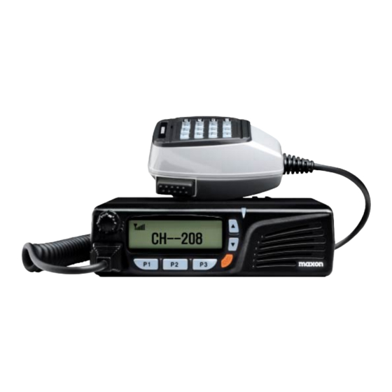
Operation Manual PM200/250 Front panel layout (Fig.3) 1.) RJ45 Microphone Socket 2.) On/Off Volume Control 3.) Alpha Numeric LCD 4.) (P1-P3) Programmable Keys 5.) Status LED 6.) Emergency Key (Orange) 7.) Up/Down Channel/Menu Keys 8.) Internal Speaker Rear panel layout (Fig. -
Page 9: Basic Programmable Feature Operation
PM200/250 Basic programmable feature Operation Function Keys There are six push-buttons on the face of the PM200/250; Up / Down (▼▲), P1, P2, P3 and Emergency, below are the default programming settings. Up/Down Keys (▼▲) These buttons allow the operator to scroll up/down through the available channels. A short press-and-release of this button will increase/decrease the channel number. -
Page 10: Monitor Key
Operation Manual PM200/250 Off Mode: Light will remain off permanently. On Mode: Light will remain on permanently. Monitor Key By pressing the Monitor button, the user shall defeat the programmed squelch operation and un-mute the speaker on the selected channel. -
Page 11: 1200/2400 Bps Key
Operation Manual PM200/250 Press the pre-programmed SMS Key (P1-P3) to transmit the SMS text. 1200/2400 bps Key Press the pre-programmed Function Key (P1-P3) to toggle between the SMS baud rate 1200 bps or 2400 bps, using the▼▲ keys. DTMF Key Select the pre-programmed Function Key (P1-P3) to enter the DTMF selection mode. -
Page 12: Basic Radio Operation
PM200/250 Basic Radio Operation Channels The PM200/250 Series radio can store up to 208 channels within the same frequency band. These channels can be selected by using the▼▲ keys. The channels can all be programmed using the PM200/250 programmer. Channel Spacing The PM-200 is capable of programmable channel spacing. -
Page 13: Squelch Options
The PM200/250 radios are capable of generating all 38 standard CTCSS tones and can also generate the 83 standard DCS codes and 83 inverted DCS codes. -
Page 14: Muting
Operation Manual PM200/250 to a channel before placing a call. This allows the user to check they are not going to transmit over a conversation from another user group. This allows more efficient use of the RF channels available. Muting Options The radio is programmable with different muting options: (please also see squelch options and programming manual). -
Page 15: Marked Idle
Operation Manual PM200/250 Busy Channel Lockout – OFF: upon PTT being pressed, the radio shall transmit regardless of the presence of carrier. Marked Idle Marked Idle enabled: can only be enabled if Busy Channel Lockout is ON. If the Busy Channel Lockout is on and carrier is detected, the radio shall be permitted to transmit if the RX squelch option is valid. -
Page 16: Scanning
Priority Scan A priority channel can be allocated using the PM200/250 programmer. The priority channel will be part of the list of channels that make up the scan list. The priority channel when used with other scanned channels will operate as follows: P1→S1→P1→S2→P1→S3→P1→S4→P1, etc. -
Page 17: Transmitting During Scanning
Operation Manual PM200/250 Back causes the radio to periodically ‘Look-Back’ to the priority channel for the presence of a carrier regardless of the channel that the user may be on. The frequency that the radio will ‘Look-Back’ to the priority channel can be programmed between 1 to 7 seconds in 1- second increments. -
Page 18: Priority Scan Channel Edit
Operation Manual PM200/250 Each Scan Group would be displayed as “xx_nnn_xx” means group, and nnn means Channel. To activate scan list editing for selected group, press the P1 button. You can change the Scan Group Number by using the up or down button. -
Page 19: Selcall
Operation Manual PM200/250 Selcall The PM200/250 has a comprehensive Selective Calling system. With 7 standard tone-sets plus a user defined tone set. Features include ANI, Emergency, Stun & Revive, Covert Mode, Acknowledge, and Selcall Text. Pre-program one of the Function Keys (P1-P3) as Selcall to activate. -
Page 20: Encode Call 1-3
Operation Manual PM200/250 Encode Call 1 – Call 3 There are three programmable call addresses; each call can have up to three sequences attached. To initiate a call, press the Selcall key and select the correct call number by scrolling using the ▲▼. To send the call, press the Selcall key. There are three actions associated with the call addresses. -
Page 21: Selcall Text
Operation Manual PM200/250 Covert Off – Remotely turns the radio covert mode off, i.e. the radio will return back to passive receive mode. Selcall Text When the correct Selcall tone set is received, the text is displayed. Up to 8 characters/numbers. -
Page 22: Selcall Keypad Microphone
Selcall Keypad Microphone Direct Selcall entry using Keypad microphone The PM200/250 has the ability to use a DTMF microphone. Depending on programming, various letter codes can be added into an encode sequence. “K” - If K is added to the sequence it will represent Keypad. For example if 123KK is sent, the decoded message reads 123 plus the last two digits entered on the keypad microphone “S”- If S is added to the sequence it will represent status. -
Page 23: To Edit K Key Mode
Operation Manual PM200/250 To edit K Key Mode To edit K Key code mode. During standby condition, push STR and scroll until Selcall is selected. To hold Selcall selection press RCL. Press # until K Key is displayed. Select digits (maximum two digits) using microphone key pad Press SND to store selected digits. -
Page 24: Dtmf
Operation Manual PM200/250 DTMF DTMF Call Selection Select pre-programmed Function Key (P1-P3) to enter DTMF selection mode. Set the correct DTMF Code using ▼▲. Press pre-programmed DTMF Key (P1-P3) to transmit the DTMF code. Receiving DTMF When DTMF code is received DTMF data is displayed When the received DTMF includes more than 8 characters, “►”... -
Page 25: Clearing A Dialed Number
Operation Manual PM200/250 Press the RCL key. Press the number key. The DTMF message which is stored is displayed on the LCD. Press the RCL Key. Press the #,∗ key to remove the displayed data from the LCD. The radio enters the standby mode. -
Page 26: To Recall A Stored Number From Memory
Operation Manual PM200/250 To Recall a Stored number from Memory Press and release the RCL key. Press and release the number key from which a number has been stored. Press SND to dial the recalled number. Clearing a Stored Number Press and release the RCL key. -
Page 27: Sms
Operation Manual PM200/250 SMS Selection If the transceiver has SMS assigned to it, the automatic SMS transmission function is available. Up to 9 SMS messages are available: To select SMS message Press SMS – an SMS message appears Press ▼▲ to select the desired SMS message. -
Page 28: Transmitting An Sms
Operation Manual PM200/250 Transmitting an SMS 9 SMS memory channels are available and the messages can be edited via PC Programming and DTMF microphone SMS Transmission Using SMS memory by PC Programming Press SMS to enter the SMS code memory channel selection mode. Up to 9 SMS channels are available: Press ▼▲to select the desired SMS Code channel. - Page 29 Operation Manual PM200/250 Press the STR Key in the edit mode. Press the number key. SMS message is stored Display STORE Num] Press the SND key to transmitter the SMS data. Page 29 of 33...
-
Page 30: Function Display
Operation Manual PM200/250 Function Display (Fig.7) 1.) Signal strength indicator: Indicates relative signal strength level 2.) X Indicator: Appears while transmitting 3.) Scan Indicator: Appears at the scan Channel 4.) P Scan Indicator: Appears at the Priority scan Channel 5.) Key Lock Indicator: Appears when the key lock function is on. -
Page 31: Pc Programmer
Operation Manual PM200/250 PC Programmer Computer Pentium II processor or faster (recommended) Operating System Microsoft Windows 98, 2000, NT, XP (recommended) Page 31 of 33... -
Page 32: Warning Status Messages
Operation Manual PM200/250 Warning Status Messages DESCRIPTION LCD MESSAGE or COLOR Comments PM250/200 AUDIBLE TONE Power On Model and Five Beeps Software version shall be displayed after LCD All Display. Button Single Beep Busy Yellow Correct Call Green Transmit In Scan Mode... -
Page 33: Contact Details
Operation Manual PM200/250 Contact Details Should you have any queries regarding this manual, or the information within it, please contact: Maxon House, Cleveland Road, Hemel Hempstead, Hertfordshire, United Kingdom, HP2 7EY Tel: + 44 (0) 1442 267 777 Fax: + 44 (0) 1442 215 515 info@maxoncic.co.uk...
Need help?
Do you have a question about the PM200 and is the answer not in the manual?
Questions and answers