Table of Contents
Advertisement
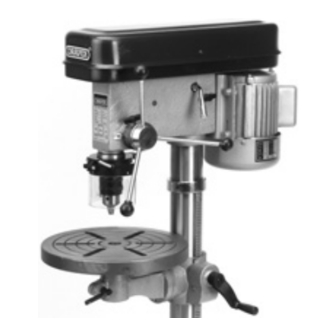
DRILL PRESS
STOCK No.36389
PART No.D16/16
52062
D16/16F
• INSTRUCTIONS •
IMPORTANT: PLEASE READ THESE INSTRUCTIONS CAREFULLY TO ENSURE THE
SAFE AND EFFECTIVE USE OF THIS TOOL.
02/2001
GENERAL INFORMATION
This manual has been compiled by Draper Tools and is an integrated part of the power tool equipment, which
should be kept with the machine.
This manual describes the purpose for which this tool has been designed and contains all the necessary
information to ensure its correct and safe use.We recommend that this manual is read before any operation of
the machine, before performing any kind of adjustment to the machine, and prior to any maintenance tasks. By
following all the general safety instructions contained in this manual, it will ensure both machine and operator
safety, together with longer life of the tool itself.
All photographs and drawings in this manual are supplied by Draper Tools to help illustrate the operation of the
machine.
Whilst every effort has been made to ensure accuracy of information contained in this manual, the Draper Tool
policy of continuous improvement determines the right to make modifications without prior warning.
Advertisement
Table of Contents

Related Manuals for Draper D16/16


Summary of Contents for Draper D16/16
-
Page 1: Drill Press
02/2001 GENERAL INFORMATION This manual has been compiled by Draper Tools and is an integrated part of the power tool equipment, which should be kept with the machine. This manual describes the purpose for which this tool has been designed and contains all the necessary information to ensure its correct and safe use.We recommend that this manual is read before any operation of... -
Page 2: Table Of Contents
Operation and Use ....................10-14 Trouble Shooting......................14 Optional Accessories ....................15 DECLARATION OF CONFORMITY Draper Tools Ltd. Hursley Road, Chandler’s Ford, Eastleigh, Hampshire. SO53 1YF. England. Declare under our sole responsibility that the product: Stock Nos:- 36389 & 52062. Part Nos:- D16/16 & D16/16F. -
Page 3: Specification/Guarantee
This guarantee applies in lieu of any other guarantee expressed or implied and variations of its terms are not authorised. Your Draper guarantee is not effective unless you can produce upon request a dated receipt or invoice to verify your proof of purchase within the 12 month period. -
Page 4: Power Supply
(i.e. red). Fuse covers are available from your Draper Tools stockist. If the fitted plug is not suitable, it should be cut off and destroyed. *The end of the cable should now be suitably prepared and the correct type of plug fitted. -
Page 5: General Safety Instructions
IMPORTANT Draper Tools Limited recommends that this machine should not be modified or used for any application other than that for which it was designed. If you are unsure of its relative applications do not hesitate to contact us in writing and we will advise you. -
Page 6: Additional Safety Rules/Unpacking And Checking Contents
Please contact the stockist where your purchase was made if you have any enquiries, eg problems with assembly, apparent missing/damaged parts, help with accessories available or technical advice or alternatively call the Draper Helpline on (023) 8049 4344. - 5 -... -
Page 7: Getting To Know Your Drill Press
GETTING TO KNOW YOUR DRILL PRESS MOTOR TABLE LOCKING HANDLE PULLEY COVER COLUMN MOTOR PULLEY BASE INTERMEDIATE PULLEY RACK SPINDLE PULLEY TABLE RISE AND FALL HANDLE SPECIFICATION LABEL RACK SECURING RING DOWN FEED ASSEMBLY NO-VOLT TYPE ON/OFF SWITCH CHUCK GUARD DRIVE BELT - TENSION ADJUSTER CHUCK RISE AND FALL LOCKING HANDLE... -
Page 8: Assembly
ASSEMBLY ASSEMBLING THE DRILL PRESS Fig.2. 1. Secure column to base using the four bolts . Loosen grub screw and remove collar along with the rack Fig.3. 2. Locate worm gear into hole shown in Fig.3. Fig.4. 3. Place rack in position in table bracket, as shown in Fig.4. - Page 9 ASSEMBLY 4. Ease table bracket and rack all the way down Fig.5. onto the column. Replace collar and re- tighten the grub screw, locking rack into place. Fig.6. 5. Slide table into the table bracket as shown in Fig.6 and lock into place using the table locking handle 6.
-
Page 10: Assembly
ASSEMBLY 8. Screw the three downfeed handles into the three holes located in the pinion shaft as shown in Fig 8. Fig.8. 9. Making sure that the chuck is opened to its capacity, place it down on a bench. Clean any excess grease off the large end of the spindle . -
Page 11: Operation And Use
OPERATION AND USE NO-VOLT ON/OFF SWITCH: (Fig 12) Fig.12. The drill is fitted with a no-volt switch In the event of a power failure the drill press will have to be manually re-started. To switch the drill press on push the button marked To switch the drill press off push the button marked... - Page 12 OPERATION AND USE SPINDLE SPEEDS Fig.13. Sixteen spindle speeds of: 240, 320, 360, 470, 540, 580, 860, 880, 1130, 1270, 1350, 1560, 1990, 2020, 2480 and 3150 are available with your drill. The highest speed is obtained when Spindle Motor the belt is on the largest step of the motor pulley and the smallest step of the spindle pulley as shown in Fig.
- Page 13 OPERATION AND USE 1. The table Fig. 17 can be raised or Fig.17. lowered on the drill press column by loosening the table clamp handle turning the table raising and lowering handle . After the table is at the desired height, tighten handle 2.
- Page 14 OPERATION AND USE ADJUSTING SPINDLE RETURN SPRING Fig.22. For the purpose of automatically returning the spindle upward after a hole has been drilled, a spindle return spring is provided in the spring housing Fig. 22. This spring has been properly adjusted at the factory and should not be disturbed unless absolutely necessary.
-
Page 15: Trouble Shooting
OPERATION AND USE The following directions will give the inexperienced operator a start on common drill press operations. Use scrap material for practice to get the feel of the machine before attempting regular work. CORRECT DRILLING SPEEDS Factors which determine the best speed to use in any drill press operations are: Type of material being worked, Size of hole, Type of drill or other cutter,... -
Page 16: Optional Accessories
OPTIONAL ACCESSORIES The following accessories are available from your local Draper stockist. WOOD MORTICING ATTACHMENT 25560 60mm 33686 55mm 36577 55mm DRILL PRESS VICES PART No.DPV Manufactured from cast iron with fully hardened jaws. Carton packed. STOCK JAW-MM JAW-MM WIDTH... - Page 17 NOTES - 16 -...
- Page 18 NOTES - 17 -...
- Page 19 NOTES - 18-...
- Page 20 ©Published by Draper Tools Ltd. No part of this publication may be reproduced, stored in a retrieval system or transmitted in any form or by any means, electronic, mechanical photocopying, recording or otherwise without prior permission in writing from Draper Tools Ltd.
Need help?
Do you have a question about the D16/16 and is the answer not in the manual?
Questions and answers
What size is pillar (14) hight and width, please.
The Draper D16/16 has a column (pillar) diameter of 71mm and a height of 960mm.
This answer is automatically generated
@Mr. Anderson thank you
What size is the column (12) hight and width, please.
The Draper D16/16 column has a height of 960mm and a diameter (width) of 71mm.
This answer is automatically generated