Table of Contents
Advertisement
Quick Links
IMPORTANT: PLEASE READ THESE INSTRUCTIONS CAREFULLY TO ENSURE THE SAFE AND
GENERAL INFORMATION
This manual has been compiled by Draper Tools and is an integrated part of the product with which it is enclosed and
should be kept with it for future references.
This manual describes the purpose for which the product has been designed and contains all the necessary information
to ensure its correct and safe use. We recommend that this manual is read before any operation or, before performing
any kind of adjustment to the product and prior to any maintenance tasks. By following all the general safety instructions
contained in this manual, it will ensure both product and operator safety, together with longer life of the product itself.
All photographs and drawings in this manual are supplied by Draper Tools to help illustrate the operation of the product.
Whilst every effort has been made to ensure accuracy of information contained in this manual, the Draper Tools policy of
continuous improvement determines the right to make modifications without prior warning.
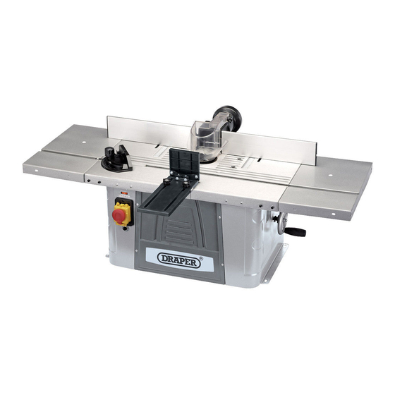
Bench Mounted
Spindle Moulder
Stock No.09536
EFFECTIVE USE OF THIS PRODUCT.
INSTRUCTIONS FOR
Part No.BMSM
Advertisement
Table of Contents

Subscribe to Our Youtube Channel
Related Manuals for Draper 09536


Summary of Contents for Draper 09536
- Page 1 EFFECTIVE USE OF THIS PRODUCT. GENERAL INFORMATION This manual has been compiled by Draper Tools and is an integrated part of the product with which it is enclosed and should be kept with it for future references. This manual describes the purpose for which the product has been designed and contains all the necessary information to ensure its correct and safe use.
-
Page 2: Table Of Contents
This guarantee applies in lieu of any other guarantee expressed or implied and variations of its terms are not authorised. Your Draper guarantee is not effective unless you can produce upon request a dated receipt or invoice to verify your proof of purchase within the guarantee period. -
Page 3: Specification
SPECIFICATION The Draper Tools policy of continuous improvement determines the right to change specification without notice. Stock no........................... 09536 Part no..........................BMSM Rated voltage......................230V~50Hz Rated input ........................1500W Spindle speed ....................11,500 - 24,000rpm Spindle travel ........................0-40mm Table size ....................... 610 x 360mm Table size with extension wings................ -
Page 4: Power Supply
POWER SUPPLY CAUTION: Risk of electric shock. Do not open. This appliance is supplied with a moulded 3 pin mains plug for your safety. The value of the fuse fitted is marked on the pin face of the plug. Should the fuse need replacing, ensure the substitute is of the correct rating, approved to BS1362 and ASTA or BS Kite marked. -
Page 5: General Safety Instructions
GENERAL SAFETY INSTRUCTIONS GENERAL SAFETY INSTRUCTIONS 13. DO NOT OVERREACH WARNING: When using electric tools basic safety Keep proper footing and balance at all times. precautions should always be followed to reduce the 14. MAINTAIN TOOLS WITH CARE risk of fire, electric shock and personal injury including Keep cutting tools sharp and clean for better and the following. -
Page 6: Additional Safety Instructions
ADDITIONAL SAFETY INSTRUCTIONS WARNING 14. IF YOUR SPINDLE MOULDER MAKES AN For your own safety, do not operate your spindle UNFAMILIAR NOISE OR IF IT VIBRATES moulder until it is completely assembled and installed EXCESSIVELY, CEASE OPERATING IMMEDIATELY according to the instructions..and until you have read UNTIL THE SOURCE HAS BEEN LOCATED AND THE and understood the safety rules, assembly procedures, PROBLEM CORRECTED. -
Page 7: Getting To Know Your Spindle Moulder
GETTING TO KNOW YOUR SPINDLE MOULDER On/off switch (emergency stop switch Work table. located on the switch cover). Dust extraction adaptor. Variable speed switch. Upper workpiece guide. Reducing bushes. Height adjustment handle. Upper guide bracket. Right extension table. Lower workpiece guide. Left extension table. - Page 8 GETTING TO KNOW YOUR SPINDLE MOULDER A. 2 x M6 Bolts J. 11 x M5 Washers S. 4 x Rubber Washers B. 1 x Pin K. 6 x Small M5 Washers T. 4 x C Clips C. 2 x Dome Head Bolts L.
-
Page 9: Assembly
ASSEMBLY - ASSEMBLY OF REAR MOULDED FENCE (Figs.1 - 3): FIG.1 - Slide the movable back plate into the grooves on the rear moulded fence . Fig.1. - Attach the movable back plate to the rear moulded FIG.2 fence using bolt . - Page 10 ASSEMBLY - FITTING THE LEFT & RIGHT REAR FENCE PLATES TO FIG.4 THE REAR MOULDED FENCE (Figs.4 - 6): - slide 2 securing bolts into each fence piece Fig 4. - With the locating slot lower, locating the securing bolts FIG.5 into the holes in the rear moulded fence.
- Page 11 ASSEMBLY - FITTING THE ROUTER BIT GUARD (Fig.8): FIG.8 - The router bit guard must be used when not using the upper and lower blade guides, attach the bit guard by lining up the fixing holes on the fence and guard and inserting pin .
- Page 12 ASSEMBLY - Repeat with the right hand hole and bolt , secure FIG.12 with plastic nuts and washers (Figs.12 & 13). FIG.13 - ATTACHING THE SIDE EXTENSION WINGS (Figs.14 - 16): FIG.14 - The extension wings are handed to line up the slot in the table, to attach them line up the side flanges and insert them into the slots at the sides of the work table.
- Page 13 ASSEMBLY - Using 3 hex bolts , 3 washers and 3 spring FIG.16 washers attach the extensions from underneath on either side. - ASSEMBLY OF THE LOWER PUSH GUIDE (Figs.17 & 19): - Fix the lower push guide bracket to the work table using 2 cross slot screws Fig.17.
- Page 14 ASSEMBLY - ATTACHING THE MITRE GUIDE (Fig.20): FIG.20 - The mitre guide is used when the operator wishes to perform angles cuts, it simply slides into the work table slot. Fig.20. - The spindle moulder is supplied with a selection of insert plates , 1,2 or 3 of them can be fitted depending upon the router bit size.
-
Page 15: Operation And Use
OPERATION AND USE FIG.24 - SWITCHING SPINDLE MOULDER ON/OFF FIG.25 (Figs.25&26): - Push tab on bottom to release cover and holding cover up, press the I button to start the machine. To stop the machine, allow the cover to drop and when you wish for the machine to stop close the cover, the stop button inside will deactivate the machine, alternatively press the O button. - Page 16 OPERATION AND USE - Variable Speed (Fig.28): FIG.28 - The spindle moulder is fitted with a variable speed dial , the dial has 5 settings with 1 being the slowest and 5 being the highest - Router bit height adjustment (Figs.29&30): - The spindle moulder has a spindle travel of 0-40mm, the height can be changed by turning the hand wheel FIG.29...
- Page 17 OPERATION AND USE - Upper workpiece guide (Figs. 32-34): FIG.32 - To use the upper workpiece guide you must attach the support bracket. To do this you must first remove the router bit guard. Using 2 bolts , washers and nuts attach upper workpiece guide support bracket to fence, you may need to remove the cross bar from...
-
Page 18: Disposal Of Power Tools
DISPOSAL OF POWER TOOLS - At the end of the machine’ s working life, or when it can no longer be repaired, ensure that it is disposed of according to national regulations. - Contact your local authority for details of collection schemes in your area. In all circumstances: Do not dispose of power tools with domestic waste. - Page 19 NOTES - 18 -...
- Page 20 - Sales Desk: (023) 8049 4333 - General Enquiries: (023) 8026 6355 - Service/Warranty Repair Agent For aftersales servicing or warranty repairs, please contact the Draper Tools Helpline for details of an agent in your local area. YOUR DRAPER STOCKIST DKDH0716...
Need help?
Do you have a question about the 09536 and is the answer not in the manual?
Questions and answers