
Subscribe to Our Youtube Channel
Related Manuals for Audio Technica 2000 Series


Summary of Contents for Audio Technica 2000 Series
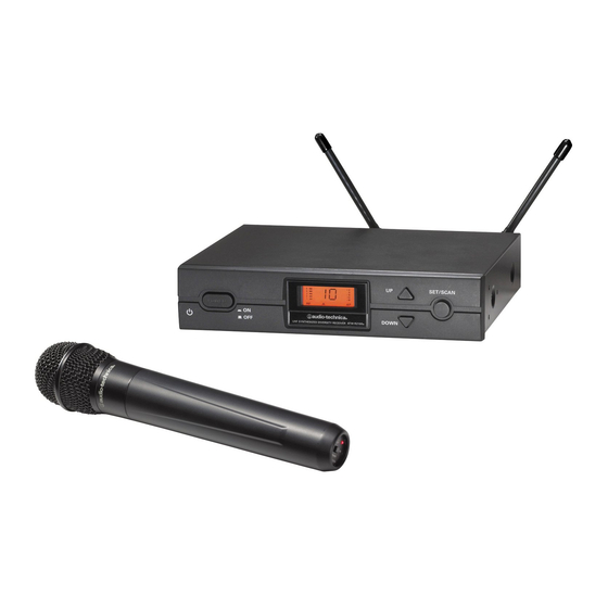
- Page 1 2000 Series Frequency-agile True Diversity UHF Wireless System Installation and Operation...
- Page 2 • To prevent fire or shock hazard, do not expose this appliance to rain or moisture. The band letter reference at the end of 2000 Series Stock Numbers • To prevent fire, do not place any naked flame sources (such as indicates what band system/component operates in.
-
Page 3: Receiver Installation
Loop the small cord from the DC plug over the cord hook band that are used in the 2000 Series have been selected for multi- above the jack, to keep the plug from being detached by an accidental channel compatibility. -
Page 4: Receiver Controls And Functions
2000 Series Installation and Operation Receiver Controls and Functions Fig. B – Front Panel Controls and Functions Fig. C – Receiver LCD Window Display 1. POWER SWITCH: Press the Power switch in to turn the receiver on. The LCD window will light, and the operating channel number will be displayed in the window. - Page 5 2000 Series Installation and Operation Fig. D – Rear Panel Controls and Functions 15. AF LEVEL CONTROL: Adjusts audio output level of both AF output 10. ANTENNA INPUT JACK: BNC-type antenna connector for jacks. Factory setting maximum output—fully clockwise. Tuner “B. ” Attach the antenna directly, or extend it with a low-loss antenna cable.
-
Page 6: Transmitter Controls And Functions
If the received signal is marginal, experiment with different Charging Contacts transmitter positions on your body or instrument or try repositioning the receiver. Do not attempt to modify the transmitting antenna. Replace it only with the same parts, available from the Audio-Technica Service Department. -
Page 7: System Operation
The LCD display will light up. If two or more of the RF LCD segments The 2000 Series handheld transmitter has factory pre-set audio input light up at this point, there may be RF interference in the area. If this levels. - Page 8 2000 Series Installation and Operation Setting Levels (Continued) Fig. E – UniPak Transmitter Open ® ATW-T210a UniPak Transmitter ® Trimmer adjustments in the UniPak transmitter (Fig. E ) will enable you ® to use microphones or instruments with different output levels.
-
Page 9: Specifications
2000 Series Installation and Operation Specifications † Overall System ATW-T210a UniPak Transmitter ® UHF Operating Frequencies RF Power Output (50 ohms) High: 30 mW, Low: 10 mW Frequency Range Number of Channels (switchable) Band D: 656.125 to 678.500 MHz Spurious Emissions... - Page 10 Frequency-MHz safety allocations (TV Channel 14) are outside of the 2000 Series operating bandwidth. 487 . 125 * The 2000 Series operates in TV channels 16-20; Channels 14 and 15 are outside the 2000 Series 487 . 625 operating bandwidth.
- Page 11 Statement of Compliance...
- Page 12 Internet: www.audio-technica.com. Para reduzir o impacto ecológico de um documento impresso de várias linguas, a Audio-Technica providência as informações dos seus produtos em diversas linguas na www.audio-technica.com. Per evitare l’impatto ambientale che la stampa di questo documento determinerebbe, le informazioni sui prodotti sono disponibili online in diverse lingue sul sito www.audio-technica.com.
Need help?
Do you have a question about the 2000 Series and is the answer not in the manual?
Questions and answers