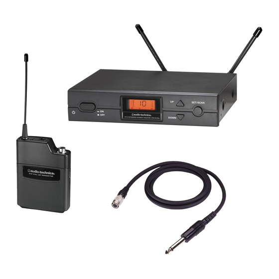
Audio Technica ATW-2110 Installation And Operation Manual
2000 series professional uhf wireless systems unipak transmitter system handheld dynamic microphone system
Hide thumbs
Also See for ATW-2110:
- Installation and operation manual (12 pages) ,
- Installation and operating manual (62 pages) ,
- Manual (12 pages)
Summary of Contents for Audio Technica ATW-2110
- Page 1 2000 Series Professional UHF Wireless Systems ATW-2110 UniPak ™ Transmitter System ATW-2120 Handheld Dynamic Microphone System Installation and Operation...
-
Page 2: Installation And Operation
The circuits inside the receiver and transmitter have been precisely adjusted for optimum performance and compli- ance with federal regulations. Do not attempt to open the receiver or transmitter. To do so will void the warranty, and may cause improper operation. Notice to individuals with implanted cardiac pacemakers... -
Page 3: Receiver Installation
For best operation the receiver should be at least 3 ft. (1 m) above the ground and at least 3 ft. away from a wall or metal surface to minimize reflections. The transmitter should be at least 3 ft. from the receiver, as shown in Figure A. Keep... -
Page 4: Receiver Controls And Functions
DOWN Figure C-Receiver LCD Window Display 6. RF SIGNAL LEVEL INDICATOR: Shows the strength of the RF signal received from the transmitter. 7. TUNER OPERATION INDICATOR: Indicates which Tuner (A or B) has the better reception and is in operation. - Page 5 Figure D-Rear Panel Controls and Functions 10. ANTENNA INPUT JACK: BNC-type antenna connector for Tuner “B.” Attach the antenna directly, or extend it with a low-loss antenna cable. See the “Antennas” section on page 3 for more details. 11. SQUELCH CONTROL: Adjusts level of noise-muting circuit (preset at factory but can be adjusted as circumstances warrant).
-
Page 6: Transmitter Controls And Functions
Audio Input Jack Battery Indicator After the battery is installed, turn on the power switch (located on the bottom of the handheld transmitter and on the top of the Instrument/Microphone UniPak transmitter). The battery indicator LED (Fig. G/H) should LEVEL Level Trim Controls turn red. -
Page 7: System Operation
The LCD display will light up and one of the tuner operation indicator LCD segments (A or B) will light, even though the transmitter is not on. If two or more of the RF LCD segments light up at this point, there may be RF interference in the area. - Page 8 2. Set the receiver’s AF Level control to its full clockwise position (maximum). See Figure D on page 5. 3. Plug the mic or instrument into the transmitter and power up the system. 4. For MIC: Make an initial adjustment of the mixer’s level controls that will allow audio through the system.
-
Page 9: Specifications
Weight 2.2 lbs (1.0 kgs) Accessories Included Two flexible UHF antennas, rack-mount adapters, AC adapter Specifications † UNIPAK ™ TRANSMITTER RF Power Output Spurious Emissions Input Connections Batteries (not included) Current Consumption Battery Life Dimensions Net Weight (without batteries) HANDHELD TRANSMITTERS... - Page 10 Cardioid condenser instrument microphone. Includes AT8418 clip-on instrument mount. AT-GCW Hi-Z instrument/guitar cable with XLRW Connecting cable for UniPak transmitter with an XLRF-type input connector, for Lo-Z microphones with XLRM-type output terminations. Optional System Accessories RECEIVER ACCESSORIES AEW-DA660D UHF (655-680 MHz) active unity-gain antenna distribution...
- Page 11 10. Turn the transmitter off when not in use. Remove the battery if the transmitter is not to be used for a period of time. Serial Number appears on the FCC label on the back of the receiver.
-
Page 12: Visit Our Website
Audio-Technica professional wireless systems purchased in the U.S.A. are warranted for one year from date of purchase by Audio-Technica U.S., Inc. ( A. T .U.S.) to be free of defects in materials and workmanship. In event of such defect, product will be repaired promptly without charge or, at our option, replaced with a new product of equal or superior value if delivered to A.


Need help?
Do you have a question about the ATW-2110 and is the answer not in the manual?
Questions and answers