Table of Contents
Advertisement
Advertisement
Table of Contents

Related Manuals for Audio Technica System 20 PRO


Summary of Contents for Audio Technica System 20 PRO
- Page 1 System 20 PRO 2.4 GHz Wireless System User Manual English...
-
Page 2: Safety Precautions
Safety precautions Important information Warning To prevent fire or shock hazard, do not expose this apparatus to rain or moisture. Caution Do not expose this apparatus to drips or splashes. To avoid electric shock, do not open the cabinet. Refer servicing to qualified personnel only. Do not expose this apparatus to excessive heat such as sunshine, fire or the like. -
Page 3: For Customers In The Usa
Safety precautions If battery leakage comes into contact with your eyes, immediately flush with water and seek medical attention. To protect the built-in rechargeable battery, charge it at least once every 6 months. If too much time passes between charges, the life of the rechargeable battery may be reduced, or the rechargeable battery may no longer be able to be charged. -
Page 4: Rf Exposure Statement
Safety precautions RF Exposure Statement (ATW-T1401/ATW-T1402) This device complies with FCC radiation exposure limits set forth for an uncontrolled environment and meets the FCC radio frequency (RF) Exposure Guidelines. This equipment has very low levels of RF energy that is deemed to comply without testing of specific absorption rate (SAR). -
Page 5: Notes On Use
Notes on use This system Be sure to read the user manual for any microphone or cable that you attach to the product. If you use the product near a TV or radio antenna, noise may be generated in the TV or radio. If this occurs, move the product away from the device. -
Page 6: Maintenance
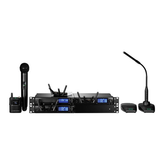
Maintenance If the product becomes stained or covered with dust, wipe it off with a dry and soft cloth. Be sure to turn the device off before performing maintenance. Dirt easily adheres to the charging terminals of the transmitter and charging station. Charging may not be possible if these products are used with dirty terminals. - Page 7 Devices compliant with this system This system consists of the following devices. Receiver ATW-R1440 Quad Receiver Transmitters (microphones) ATW-T1401 Body-Pack Transmitter ATW-T1402 Handheld Transmitter ATW-T1406 Boundary Microphone Transmitter ATW-T1407 Desk Stand Transmitter...
-
Page 8: Charging Station
Devices compliant with this system Charging station ATW-CHG3a/ATW-CHG3Na Two-Bay Charging Station... -
Page 9: Part Names And Functions
Part names and functions ATW-R1440 This receiver is a combination of a receiver chassis (ATW-RC14) and receiver unit (ATW-RU14). Display Displays the receiver state and settings menus. Control dial Turn the dial to select a setting item and press to confirm. Power button Turns the power on or off. - Page 10 Part names and functions LINK OUT port When linking multiple receivers, connect the included link cable to this port. DC input jack Connect the included AC adapter. ATW-RU14 Antenna connector Attach an included antenna. Camera thread (1/4-inch) Use this thread to secure the receiver unit when installing it externally. Indicator lamp Lights when the device is on.
- Page 11 Part names and functions ATW-T1401 Antenna Mute switch Switches between muted and unmuted.
- Page 12 Part names and functions Input connector Connect a microphone, a guitar cable, etc. Indicator lamp Lights when the device is on. This lamp also shows the status of this transmitter. Refer to "Indicator lamps" (p. 73) for details. Latch Display Shows the current status.
- Page 13 Part names and functions Mute switch Switches between muted and unmuted. Grip case Power button Turns the device on/off and performs pairing. Charging terminal USB port (USB Type-C) Use this port when updating the firmware. ATW-T1406 USB port (USB Type-C) Use this port when charging the device and when updating the firmware.
- Page 14 Part names and functions Display Shows the current status. If no buttons are pressed for a period of 30 seconds, the display will turn off. When the display turns off, press the power button to turn it back on. Power button Turns the device on/off and performs pairing.
- Page 15 Part names and functions Display Shows the current status. If no buttons are pressed for a period of 30 seconds, the display will turn off. When the display turns off, press the power button to turn it back on. Power button Turns the device on/off and performs pairing.
- Page 16 How to install the receiver Low RF signal may result if there are obstructions between the receiver antennas and transmitter. In such a case, reposition the receiver to get better reception. How to mount the antennas Failing to mount the included antennas on the receiver will result in poor radio wave reception. Mount the antennas on the receiver and screw them in.
-
Page 17: Rack Mounting
How to install the receiver Rack-mounting Use the included rack-mount adapters and fixing screws to mount the receiver on a commercially available rack. Screws for rack-mounting the receiver are not included. The required rack specifications are as follows: - EIA-standard 19-inch rack - 1U-size attachable rack - Rack with a shelf on which the receiver is placed or a guide rail that supports the receiver Consider ventilation when rack-mounting to avoid heat building up in the rack. - Page 18 How to install the receiver Rack-mounting one receiver Attach the short rack-mount adapter and long rack-mount adapter to the sides. Adapters can be attached to either side of the receiver. Fully attach two fixing screws to the left side and two fixing screws to the right side. Fixing screw Short rack-mount adapter Long rack-mount adapter...
- Page 19 How to install the receiver Fixing screw Long rack-mount adapter Attach two short rack-mount adapters with one on each side. Fully attach two fixing screws to the left side and two fixing screws to the right side. Fixing screw Short rack-mount adapter...
- Page 20 How to install the receiver How to mount the legs For installation on a table or a similar surface, attach the included legs to the receiver. When rack-mounting the receiver, do not attach the legs to the receiver.
- Page 21 How to externally install the receiver unit You can remove the receiver unit from the receiver chassis and install the receiver unit by itself. How to remove the receiver unit Push the part labeled “PUSH”, and then remove the receiver unit. How to install the receiver unit with the unit holder Straighten the antennas.
- Page 22 How to externally install the receiver unit Allowing the unit holder to be attached and removed Hang the unit holder on a wood screw partially screwed into a wall or similar surface. The unit holder can be attached with either side facing up. How to attach the receiver unit Use a LAN cable (Cat. 5e or higher) to connect the external receiver unit port of the receiver chassis and the external port of the receiver unit.
- Page 23 How to externally install the receiver unit Attach the receiver unit to the unit holder. If passing the LAN cable through the wall, attach the holder cover. You can hide the LAN cable and the wiring hole.
- Page 24 How to externally install the receiver unit How to remove the holder cover While pressing the part indicated with the arrow, remove the cover. How to remove the receiver unit While pressing the hook, press the receiver unit from below to remove it.
- Page 25 How to externally install the receiver unit How to link unit holders You can link receiver units by aligning their grooves and protrusions. How to install the receiver unit with the camera thread When using the angle of the camera thread, attach an angle to the camera thread (1/4-inch) of the receiver unit.
- Page 26 How to externally install the receiver unit...
- Page 27 Basic flow of using this system This section explains basic operations to allow for prompt use of this system. For detailed operations and setup methods, refer to their explanation pages. Install and wire the receiver and other devices. Pair the transmitter and the receiver. If you purchased the transmitter and receiver as a set, they are already paired.
-
Page 28: System Configuration Examples
System configuration examples ATW-R1440 (when using only one unit) The maximum number of transmitters that can be used is two when the receiver reception mode is set to “Standard” and four when this mode is set to “HD mode”. Computer Switching hub ATW-T1401/ATW-T1402 ATW-T1406/ATW-T1407... -
Page 29: How To Connect The Receiver
How to connect the receiver Basic connection This is an example of connections made when using one receiver. LAN cable XLR cable AC adapter Linking (RX linking) When using multiple receivers, link (RX link) them with the included link cable. RX linking the receivers allows you to set and monitor all the connected receivers and transmitters from a single PC on which Wireless Manager is installed. - Page 30 How to connect the receiver Base unit LAN cable XLR cable Link cable AC adapter...
- Page 31 How to connect the receiver Expansion unit...
-
Page 32: How To Charge
How to charge Charging the ATW-T1401/ATW-T1402 Use charging station ATW-CHG3a/ATW-CHG3Na (sold separately) to charge the devices. For a detailed description of the charging station, see its user manual. Insert the nickel-metal hydride batteries into the transmitter before charging it. Do not charge alkaline batteries or lithium batteries. You can also charge with the ATW-CHG3/ATW-CHG3N. - Page 33 How to charge Charging the ATW-T1406/ATW-T1407 Connect the included USB cable / USB power supply adapter to the USB port (USB Type-C) of the transmitter. Insert the USB cable into the USB port in a straight (level) manner. When the charging starts, the status indicator lamp lights in red. You can also charge the device by connecting it to a USB port on a PC.
-
Page 34: Turning The Device On/Off
How to use the devices ATW-R1440 Turning the device on/off Connect the AC adapter, and then connect the power plug to an electrical outlet. With the device off, press and hold (approximately 2 seconds) the power button. Power button The device turns on and its display lights. With the device on, press and hold (approximately 2 seconds) the power button. - Page 35 How to use the devices Open the battery cover while holding the latches down. Insert the batteries according to the plus (+) and minus (−) marks found inside the battery compartment.
- Page 36 How to use the devices Turning the device on/off With the device off, press and hold (approximately 2 seconds) the power button. Power button The device turns on and its indicator lamp lights. Indicator lamp Status Lit in green Communication has been established. Flashing in red The device is searching for the receiver to communicate with.
- Page 37 How to use the devices Slide the mute switch. Slide the mute switch right to mute the device and slide the mute switch left to unmute the device. The indicator lamp displays the status. Mute switch Indicator lamp Indicator lamp Status Lit in red Muted...
-
Page 38: How To Wear The Device
How to use the devices How to wear the device You can use the belt clip to attach the device to a belt or something similar when using the device. ATW-T1402 How to insert batteries Rotate the grip case of the battery compartment to remove this case. Open the battery cover. - Page 39 How to use the devices Turning the device on/off With the device off, press and hold (approximately 2 seconds) the power button. Power button Indicator lamp The device turns on and its indicator lamp lights. Indicator lamp Status Lit in green Communication has been established.
- Page 40 How to use the devices Slide the mute switch. Slide the mute switch down to mute the device and slide the mute switch up to unmute the device. The indicator lamp displays the status. Indicator lamp Mute switch Indicator lamp Status Lit in red Muted...
- Page 41 How to use the devices Power button Indicator lamp The device turns on and its indicator lamp lights. Indicator lamp Status Lit in green Communication has been established. Flashing in red The device is searching for the receiver to communicate with. Lit in red Communication has been established (In Conference mode).
- Page 42 How to use the devices Talk switch Talk indicator lamp Status indicator lamp Talk indicator lamp / status Status indicator lamp Lit in red Muted Lit in green Unmuted Muted (in Conference mode) Lit in red Unmuted (in Conference mode) How to attach a gooseneck microphone (ATW-T1407 only) To use a gooseneck microphone, attach it to a desk stand transmitter.
- Page 43 How to use the devices Refer to the user manual of the gooseneck microphone for details on how to handle it. For details on compatible gooseneck microphones, contact your local Audio-Technica dealer. When using a gooseneck microphone with an LED (ATW-T1407 only) When using a gooseneck microphone with an LED, carry out the procedure under "Setting the indicator lamp (ATW- T1406/ATW-T1407)"...
- Page 44 How to use the devices...
-
Page 45: How To Pair Devices
How to pair devices In this user manual, making a receiver and transmitter register each other is referred to as a “pairing”. Set the receiver to pairing mode. Refer to "Pairing mode" (p. 62) for details. “Pairing” appears on the display of the receiver. With the transmitter off, press and hold (approximately 5 seconds) the power button. -
Page 46: How To Read The Display
How to read the display ATW-R1440 Main screen ROOMABAB ID:244 +20dB +20dB +20dB +20dB Name Displays the set name. Device ID Displays the device ID of the receiver. HD mode Displayed during HD mode. Mix output Displayed during mix output. Link status Displayed during RX linking. - Page 47 How to read the display AF status Displays the audio status of the connected transmitter. : Displayed when the level meter display is set to “Pre”. Displays the level of the received audio signal. : Displayed when the level meter display is set to “Post”. Displays the output level of the receiver. : Indicates that the device is at peak AF status.
- Page 48 How to read the display Each press of the CH MENU button switches the channel to set. You can set up to two channels when the reception mode is “Standard” and up to four channels when the reception mode is “HD mode”. UTILITIES UTILITIES IDENTIFY...
- Page 49 How to read the display +10dB Transmitter ID Gain level Battery level Displays the battery level of the transmitter. : Charging is in progress. : 70% or more battery power remaining. : 40% or more battery power remaining. : 20% or more battery power remaining. : 10% or more battery power remaining.
- Page 50 Displayed messages (ATW-R1440) Message Description No receiver unit No receiver unit is connected to the receiver. Initializing The receiver unit is connecting to the receiver. The number of sequential receivers that can be linked has Exceeding Rx link limit been exceeded. Up to five receivers can be linked. Rebooting The receiver is restarting.
-
Page 51: Receiver Settings
Setting ATW-R1440 Various settings can be made from the screens shown on the display. Receiver settings Basic operation Press the control dial. Control dial The receiver settings menu appears. Turn the control dial to select the receiver settings menu and setting. Press the control dial to confirm the selection. - Page 52 Setting ATW-R1440 Receiver settings menu list Receiver settings menu Details DEVICE ID Set the device ID. NAME Set the name. RF MODE Set the reception mode. AUTO LOCK Set this function to prevent the settings from being changed. OUTPUT MIX Set whether to mix and output audio.
-
Page 53: Setting The Reception Mode
Setting ATW-R1440 Alphabetic characters (uppercase letters), numbers, symbols (_, +, −, #, &, period), spaces The number of characters that can be entered is 8. From the receiver settings menu, select “NAME” and press the control dial. Turn the control dial, select the desired character, and then press the control dial. The character is input, and the cursor moves. -
Page 54: Unlocking The Receiver
Setting ATW-R1440 Setting this to “On” makes operation impossible. To change the settings, unlock the receiver. From the receiver settings menu, select “UTILITIES” and press the control dial. Turn the control dial to select “AUTO LOCK” and press the control dial. Select “On”/“Off”... -
Page 55: Setting The Control Dial
Setting ATW-R1440 Setting the level meter display Switch the AF status on the main screen to the “Pre” meter (the received audio signal level) or “Post” meter (the output level of the receiver). The default setting is “Pre”. Changing this setting changes the mark in the AF status part. From the receiver settings menu, select “UTILITIES”... -
Page 56: Saving Presets
Setting ATW-R1440 From the receiver settings menu, select “UTILITIES” and press the control dial. Turn the control dial to select “CTRL DIAL” and press the control dial. Turn the control dial to select “Default”/“Invert” and press the control dial. The setting is complete. Saving presets You can save the receiver settings. -
Page 57: Checking The Version
Setting ATW-R1440 Resetting Reset receiver settings to factory defaults. From the receiver settings menu, select “UTILITIES” and press the control dial. Turn the control dial to select “RESET” and press the control dial. Turn the control dial to select “Yes” and press the control dial. Turn the control dial to select “Yes”... -
Page 58: Setting The Remote Control
Setting ATW-R1440 IP settings From the receiver settings menu, select “NETWORK” and press the control dial. Turn the control dial to select “IP SETTING” and press the control dial. Select an item you want to set and press the control dial. Item Details Set how to obtain IP addresses. - Page 59 Setting ATW-R1440 Item Details Notification Set to receive notifications from the receiver during remote control. Set whether to include AF and RF levels in notifications from the LVL Notify receiver during remote control. Multicast IP Set the address for multicast. Multicast port Set the port number for multicast.
- Page 60 Setting ATW-R1440 Turn the control dial to select “On”/“Off” and press the control dial. Turn the control dial to select “Reboot”/“Later” and press the control dial. If you selected “Reboot”, the receiver restarts to complete the setting. If you selected “Later”, the setting is complete but is not applied until the receiver restarts. Setting the NTP (Network Time Protocol) Set the NTP.
-
Page 61: Checking The Mac Address
Setting ATW-R1440 Checking the MAC address From the receiver settings menu, select “NETWORK” and press the control dial. Turn the control dial to select “MAC ADDRESS” and press the control dial. The MAC address appears. Channel settings Basic operation Press the CH MENU button. Each press of the CH MENU button switches the channel to set. - Page 62 Setting ATW-R1440 BACK button While on the settings screen, the display will return to the main screen if approximately 30 seconds pass without any operations being performed. Channel settings menu list Channel settings menu Details PAIR Pair with a transmitter. LINE/MIC Set the LINE/MIC level.
-
Page 63: Pairing Mode
Setting ATW-R1440 Pairing mode Press the CH MENU button to select the channel to set. Each press of this button switches the channel to set. UTILITIES UTILITIES IDENTIFY IDENTIFY LINE LINE PAIR PAIR LINE / MIC LINE / MIC LEVEL LEVEL UTILITIES UTILITIES... -
Page 64: Setting The Output Level
Setting ATW-R1440 Transmitter ID Turn the control dial to select “Pair” and press the control dial. “Pairing” appears on the display of the receiver, and pairing with the transmitter starts. When pairing is successful, “Pairing succeeded” appears. When a timeout occurs, “Timeout” appears. When pairing is canceled, “Canceled” appears. When pairing fails, “Failed”... - Page 65 Setting ATW-R1440 Setting the HPF (High-Pass Filter) Press the CH MENU button to select the channel to set. Each press of this button switches the channel to set. Turn the control dial to select “HPF” and press the control dial. Turn the control dial to select “ON”/“OFF”...
- Page 66 Setting ATW-R1440 The setting is complete. Setting the input connector (ATW-T1401 only) Set the connection destination of the input connector to “MIC” (microphone) or “INST” (guitar cable, etc.). Press the CH MENU button to select the channel to set. Each press of this button switches the channel to set. Turn the control dial to select “TX SETTING”...
- Page 67 Setting ATW-R1440 Setting the mute mode (ATW-T1406/ATW-T1407) Press the CH MENU button to select the channel to set. Each press of this button switches the channel to set. Turn the control dial to select “TX SETTING” and press the control dial. Turn the control dial to select “MUTE MODE”...
- Page 68 Setting ATW-R1440 Turn the control dial to select “On”/“Off” and press the control dial. Item Details The indicator lamp lights. The indicator lamp is always off. The setting is complete. Setting the indicator lamp (ATW-T1406/ATW-T1407) You can change the color setting of the displayed indicator lamp. With the ATW-T1407, configure this setting when using a gooseneck microphone with an LED.
-
Page 69: Setting The Timeout
Setting ATW-R1440 Press the CH MENU button to select the channel to set. Each press of this button switches the channel to set. Turn the control dial to select “TX SETTING” and press the control dial. Turn the control dial to select “BATTERY” and press the control dial. Turn the control dial to select “Alkaline”/“NiMH”/“Lithium”... -
Page 70: Setting The Equalizer
Setting ATW-R1440 Press the CH MENU button to select the channel to set. Each press of this button switches the channel to set. Turn the control dial to select “TX SETTING” and press the control dial. Turn the control dial to select “VERSION”. The firmware version appears. -
Page 71: Setting The Compressor
Setting ATW-R1440 Turn the control dial to select “EQ:” and press the control dial. Turn the control dial to select “On” and press the control dial. You can now select the equalizer setting. Turn the control dial to select “Recall preset:” and press the control dial. Turn the control dial to select “NEUTRAL”/“WARM”/“BRIGHT”/“USER1”/“USER2”/“USER3”/“USER4”... - Page 72 Setting ATW-R1440 Deleting transmitter registration You can delete the registration of the paired transmitter. This is displayed when multipairing is set to “On”. The transmitter’s receiver information will not be deleted. Press the CH MENU button to select the channel to set. Each press of this button switches the channel to set.
-
Page 73: Wireless Manager
Wireless Manager Wireless Manager is dedicated software that supports the wireless operation of Audio-Technica products. Connecting the receiver to a computer running Windows/macOS allows you to monitor the status of and control the receiver. You can configure device settings in an offline manner and even import settings by establishing an online connection with a device. -
Page 74: Status Indicator Lamp
Indicator lamps ATW-RU14 Indicator lamp Status Flashing in green Communication has not been established. Flashing quickly in green Pairing is in progress. Lit in green Communication has been established. ATW-T1401/ATW-T1402 Indicator lamp Status Lit alternately in red/green Pairing is in progress. Lit in green Communication has been established. - Page 75 Indicator lamps Status indicator lamp (in Conference mode) Indicator lamp Status Lit alternately in red/green Pairing is in progress. Lit in red Communication has been established. Communication has been established, and the device is muted. Flashing in red The device is searching for the receiver to communicate with. Flashing in yellow There is no battery power.
-
Page 76: How To Update The Firmware
How to update the firmware ATW-R1440 When devices are RX linked, updating the base unit updates the expansion unit receiver as well. Use a LAN cable to connect the NETWORK port of the receiver to the computer running Windows/macOS. Launch Wireless Manager, and then select “Firmware Update” on the “Tools” menu. ATW-T1401/ATW-T1402/ATW-T1406/ATW-T1407 Turn off the transmitter. - Page 77 How to update the firmware Launch Wireless Manager, and then select “Firmware Update” on the “Tools” menu.
-
Page 78: Troubleshooting
Troubleshooting The receiver power can’t be turned on Make sure that the AC adapter is connected properly. Make sure that the receiver is on. The transmitter power can’t be turned on Make sure that batteries are in place. Check the battery level of the rechargeable battery. There is no audio / the audio level is low Make sure that the receiver and transmitter are on. - Page 79 Dimensions ATW-R1440 209.8 (Unit: mm) With antennas connected (Unit: mm)
- Page 80 Dimensions ATW-T1401 63.7 22.7 (Unit: mm) ATW-T1402 (Unit: mm)
- Page 81 Dimensions ATW-T1406 90.5 31.9 (Unit: mm)
- Page 82 Dimensions ATW-T1407 90.5 47.6 (Unit: mm)
-
Page 83: Overall System Specifications
Specifications Overall system specifications Operating frequencies 2,402 to 2,480 MHz Dynamic range 120 dB (A-weighted), typical Total harmonic distortion < 0.05%, typical Operating range 60 m (197') 20 to 20,000 Hz System frequency response Standard: 2.8 ms Delay HD mode: 6.7 ms Standard: 24-bit/48 kHz Audio sampling rate HD mode: 24-bit/48 kHz Encryption system AES128... - Page 84 Specifications ATW-RU14 Modulation mode GFSK RF output power 10 mW EIRP RF sensitivity −90 dBm, typical Antenna 1/2 wave dipole antenna, true diversity External connection port RJ45 12 V DC (RC14) Power supply Operating temperature range 0 to 40°C (32 to 104°F) Dimensions 86.0 mm (3.4") × 70.2 mm (2.8") × 18.7 mm (0.74") (W × D × H) Weight 77 g (2.7 oz)
- Page 85 Specifications ATW-T1402 Modulation mode GFSK RF output power 10 mW EIRP RF sensitivity −90 dBm, typical Antenna True diversity Dynamic Microphone type Microphone polar pattern Hypercardioid Battery 3 V DC (two 1.5 V AA) Operating temperature range 5 to 40°C (41 to 104°F) Approx. 18 hours (alkaline) Battery life Approx.
- Page 86 Specifications ATW-T1407 Modulation mode GFSK RF output power 10 mW EIRP RF sensitivity −90 dBm, typical Antenna True diversity Gooseneck microphone supported Microphone Phantom power supply 24 V DC Operating temperature range 5 to 40°C (41 to 104°F) Built-in battery 3.7 V lithium-ion battery (5.5 Wh, 1,460 mAh) When using a gooseneck microphone with no LED: Approx.
- Page 87 Trademarks ® ® Microsoft and Windows are registered trademarks of Microsoft Corporation in the United States and/or other countries. Microsoft Windows operating system is indicated in its abbreviated form as Windows. Apple and macOS are trademarks of Apple Inc., registered in the U.S. and other countries. ™...
- Page 88 System diagram (ATW-R1440) -10 to +20dB -20 to +20dB TX GAIN Comp LEVEL 30dB OUTPUT 150Hz 4-Band EQ Comp -30 to +10dB MIX GAIN MUTE LINE POST METER PRE METER -10 to +20dB -20 to +20dB TX GAIN Comp LEVEL 30dB OUTPUT 150Hz...
- Page 89 株式会社オーディオテクニカ 〒194-8666 東京都町田市西成瀬2-46-1 www.audio-technica.co.jp Audio-Technica Corporation 2-46-1 Nishi-naruse, Machida, Tokyo 194-8666, Japan www.audio-technica.com ©2024 Audio-Technica Corporation Global Support Contact: www.at-globalsupport.com 351716190-02-01 ver.1 2024.05.01...
Need help?
Do you have a question about the System 20 PRO and is the answer not in the manual?
Questions and answers