Advertisement
Table of Contents
·Thank you for purchasing a generator.
· This manual covers operation and maintenance of the
generator.
·We reserve the right to make changes at anytime without
notice and without taking any obligation.
This publication can't be reproduced without written
permission
·Pay special attention to the following words:
·If a problem should arises or if you have any questions about
your product, consult an authorized dealer.
! WARNING
this generator is designed to give safe and
Dependable service if operated according to instructions.
Read the Owner's Manual before operating the generator.
Failure to do so could result in personal injury or equipment
damage.
CATALOGUE
① SAFETY INSTRUCTIONS-------------------------------------02
② COMPONENT IDENTIFICATION---------------------------05
③ PRE-OPERATION CHECK------------------------------------07
④ STARTING THE ENGINE-------------------------------------10
⑤ GENERATOR USE---------------------------------------------12
⑥ STOPPING THE ENGINE-------------------------------------16
⑦ MAINTENANCE TIPS & INSTRUCTIONS------------------18
⑧ TRANSPORTING/STORAGE---------------------------------24
⑨ TROUBLESHOOTING (FAQS)--------------------------------25
~ 1 ~
Advertisement
Table of Contents

Related Manuals for ETQ IN1800i


Summary of Contents for ETQ IN1800i
-
Page 1: Table Of Contents
·Thank you for purchasing a generator. · This manual covers operation and maintenance of the generator. ·We reserve the right to make changes at anytime without notice and without taking any obligation. This publication can’t be reproduced without written permission ·Pay special attention to the following words: ·If a problem should arises or if you have any questions about your product, consult an authorized dealer. -
Page 2: Safety Instructions
1. SAFETY INSTRUCTIONS ·Generator is designed to give safe and dependable service if operated according to instructions. Read the Owner’s Manual before operating the generator. Failure to do so could result in personal injury or equipment damage. ·Exhaust gas is poisonous. Never run the generator in an enclosed area. - Page 3 Always refuel in a well-ventilated location. ·Wipe up spilled gasoline at once. · The muffler will become very hot during operation and remains hot for awhile after the engine has been stopped. Do not to touch the muffler while it is hot. Let the engine cool down before moving the generator indoors.
- Page 4 ! WARNING ·Always make a pre-operation inspection (page 8) before you start the engine. ·Place the generator at least 1m (3ft) away from buildings or other equipment during operation. ·Operate the generator on a level surface. If the generator is tilted, fuel spillage may result. ·Know how to stop the generator quickly and understand the operation of all the controls.
-
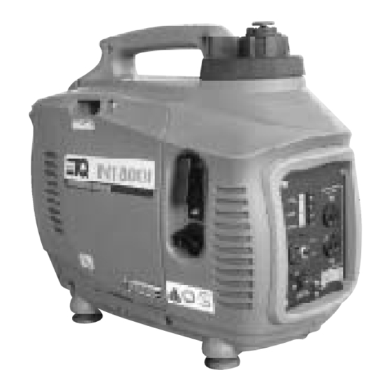
Page 5: Component Identification
2. COMPONENT IDENTIFICATION CHOKE LEVER FUEL CAP LEVER FUEL CAP CONTROL PANEL FUEL COCK LEFT SIDE MAINTENANCE COVER STARTER GRIP ENGINE SWITCH SPARK PLUG MAINTENANCE COVER MUFFLER ~ 5 ~ ... -
Page 6: Control Panel
CONTROL PANEL OIL ALERT INDICATOR LIGHT OUTPUT INDICATOR LIGHT OVERLOAD INDICATOR LIGHT DC RECEPTACLE DC CIRCULT PROTECTOR ENGINE SWITCH EARTH AC RECEPTACLE ~ 6 ~ ... -
Page 7: ③ Pre-Operation Check
3.PRE-OPERATIONCHECK Be sure to check the generator on a level surface when the engine doesn’t work. ① Check oil level. Loosen the cover screw and remove the left side maintenance cover. Remove the oil filler cap, and wipe the dipstick with a clean rag. Check the oil level by inserting the dipstick in the filler hole without screwing it in. - Page 8 Using nondetergent oil or 4-stroke engine oil could shorten the engine’s service life. Please use high-detergent, premium quality 4-stroke engine oil. Running the engine with insufficient oil can cause serious engine damage. NOTE: The Oil Alert System will automatically stop the engine before the oil level falls below the safe limit..
- Page 9 UPPER LIMIT MARK FUEL FILLER CAP OPEN ③ Check the air cleaner. Check the air cleaner element to be sure it is clean and in good condition. Loosen the cover screw and remove the left side maintenance cover. Press the latch tab on the top of the air cleaner body, remove the air cleaner cover, check the element.
-
Page 10: Starting The Engine
COVER SCREW LEFT SIDE MAINTENANCE COVER CLEANER COVER AIR CLEANER BODY AIR CLEANER ELEMENT 4. STARTING THE ENGINE Before starting the engine, disconnect the load from the DC terminals. ① Turn the fuel cap lever fully clockwise to the ON position. NOTE: Turn the fuel cap lever to the OFF position then transport the generator ②... - Page 11 Tune the fuel switch to ON position. FUEL CAP LEVER ③ Move the choke lever to the CLOSED position. NOTE: Do not use the choke when the engine is warm or the air temperature is high. CHOCK LEVER CLOSED ④ Pull the starter grip until resistance is felt, then pull the starter grip briskly toward the arrow as shown below.
- Page 12 CAUTION: Do not allow the starter grip to snap back. Return it slowly byhand. STARTER GRIP ⑤ Move the choke lever to the OPEN position as the engine warms NOTE: If the engine doesn’t work by starting several times, check the engine oil level before trouble shooting other areas.
-
Page 13: Generator Use
5. GENERATOR USE ! WARNING ·To prevent electrical shock from faulty appliances, the generator should be grounded. Connect with a heavy wire between the generator ground terminal and on external ground source. ·Connections from standby power to a building’s electrical system must be made by a qualified electrician and must comply with all applicable laws and electrical codes. - Page 14 OIL ALERT INDICATOR LIGHT OUTPUT INDICATOR LIGHT AC RECEPTACLE Output and Overload indicators The output indicator light (green) will remain ON during operating conditions. If the generator is overloaded (more than 1.0K VA), or if there is short in the connected appliance, the output indicator light (green) will go OFF, the overload indicator light (red) will go ON and current to the connected appliance will be shut off.
- Page 15 ·In DC operation, turn the switch to the OFF position. ·To prevent from creating a spark near the battery, connect charging cable first to the generator, then to the battery, Disconnect cable first then the battery. ·Connect the positive battery terminal to the positive charging cord.
- Page 16 ! WARNING ·The battery gives off explosive gases; keep sparks, flames and cigarettes away. Provide adequate ventilation when charging. ·The battery contains sulfuric acid (electrolyte). Touch skin or eyes may cause severe bums. Wear protective clothing and a face shield. - lf electrolyte touches your skin, flush with water.
-
Page 17: Stopping The Engine
6. STOPPING THE ENGINE To stop the engine in an emergency, turn the engine switch to the STOP position. IN NORMAL CONDITION: Switch off the connected equipment and pull out the inserted plug. PLUG Turn the engine switch to the STOP position. Turn the fuel switch to the OFF position. - Page 18 Turn the fuel cap lever counterclockwise to the “OFF” position. CAUTION: Be sure the fuel cap lever and the engine switch are “OFF” when stopping , transporting and/or storing the generator. FUEL CAP LEVER ~ 18 ~ ...
-
Page 19: ⑦ Maintenance Tips & Instructions
6.MAINTENANCE TIPS & INSTRUCTIONS The purpose of the maintenance and adjustment schedule is to keep the generator in the best operating condition. inspect or service as scheduled in the table below. ! WARNING Shut off the engine before performing any maintenance. lf the engine has to be running, make sure the area is well ventilated. - Page 20 ① CHANGING OIL Drain the oil while the engine is still warm to drain the oil as soon as possible. CAUTION: Make sure to turn the engine switch and the fuel cap lever OFF before draining. ·Loosen the cover screw and remove the left side maintenance cover.
- Page 21 NOTE: Please dispose of used motor oil in a manner that is compatible with the environment. We suggest you assort the oil and make an utilization of it’s unavailable elements. Do not throw in the trash or pour it on the ground. OIL FILLER HOLE OIL FILLER CAP ②...
- Page 22 COVER SCREW LEFT SIDE MAINTENANCE COVER AIR CLEANER ELEMENT AIR CLEANER GAP ELEMENT CARTION: Never run the generator without the air cleaner. Rapid engine wear may result. ·Loosen the cover screw and remove the left side maintenance ~ 22 ~ ...
- Page 23 cover. ·Press the latch tab on the top of the air cleaner body, and remove the air cleaner cover. ·Wash the element in a non-flammable or high flash point solvent and dry it thoroughly. ·Soak the element in clean engine oil and squeeze out the excess oil. ·Reinstall the air cleaner element and the cover.
- Page 24 COVER ·Remove the spark plug cap. ·Clean any dirt around the spark base. ·Use the wrench to remove the spark plug. SPARK PLUG CAP HANDLE BAR PLUG WRENCH ·Visually inspect the spark plug. Discard it if the insulator is cracked Clean the spark plug with a wire brush if it can be reused.
-
Page 25: ⑧ Transporting/Storage
8. TRANSPORTING/STORAGE Make sure to drain the fuel completely during transporting or during storage. To prevent fuel spillage when transporting or during temporary storage, the generator should be secured upright in its normal operating position, with the engine switch OFF. The fuel cap level turned fully to the “OFF”... - Page 26 9. TROUBLESHOOTING (FAQS) When the engine will not start: 1. Is there fuel in the tank? Refill the fuel tank. 2. Is the engine switch on? Turn the engine switch on. 3. Is the enough oil in the engine? Add the recommended oil 4.
- Page 27 ! WARNING Be sure there is no spilled fuel around the spark plug. If the engine still does not start, take the generator to an authorized dealer. To check: 1. Remove the spark plug cap and clean any dirt around the spark plug.
- Page 28 Appliance does not operate: Is the output indicator light ON? Is the overload indicator light ON? Check the electrical appliance or equipment for any defects. Take the generator to an authorized dealer Replace the electrical appliance or equipment. Take the electrical appliance or equipment to an electrical shop for repair.
-
Page 29: Specifications
10. SPECIFICATIONS ENGINE Engine type 4-stroke, overhead valve, single cylinder Displacement 99.3cc Bore×Stroke φ58×37.6 Compression ratio 10:1 Engine speed 3000~4800rpm Cooling system Forced air Ignition system Full transistor Oil capacity 0.5L Fuel tank capacity Spark plug E7RTC Noise Level (ISO 8528-10) <60dB (A) Generator Rated Voltage (V) - Page 30 MODEL: IN1800i 4 – stroke Instructions for use Generator OWNER’S MANUAL Inverter Generator ~ 30 ~ ...
Need help?
Do you have a question about the IN1800i and is the answer not in the manual?
Questions and answers
I would like to know where the lines go to from the carb into the system around the inverter
Where should the proper oil level be on dipstick