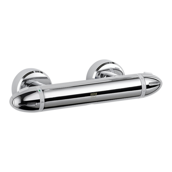
Summary of Contents for Mira Coda
- Page 1 MIra Coda THErMoSTaTIC Bar VaLVE Installation & User Guide These instructions must be left with the user.
-
Page 2: Table Of Contents
ConTenTs Introduction ..................... 3 Patents ....................3 safety : Warnings ..................4 Pack Contents ..................5 Specifications ..................6 Pressures ..................... 6 Temperatures ..................6 Thermostatic Shut-down ..............6 Connections ..................6 Dimensions ....................7 Installation ....................8 Suitable Plumbing Systems ..............8 General .................... -
Page 3: Introduction
InTroDuCTIon Thank you for purchasing a quality Mira product. To enjoy the full potential of your new product, please take time to read this guide thoroughly, having done so, keep it handy for future reference. The Mira Coda thermostatic bar valve is a shower control designed for wall mount installations. -
Page 4: Safety : Warnings
: WarnIngs Mira thermostatic mixers are precision engineered and should give continued safe and controlled performance, provided: They are installed, commissioned, operated and maintained in accordance with the manufacturer’s recommendations. Periodic attention is given, when necessary, to maintain the product in good functional order. -
Page 5: Pack Contents
PaCk ConTenTs Tick the appropriate boxes to familiarise yourself with the part names and to confirm that the parts are included. 1 x Mira Coda Bar Valve 2 x Concealing Plates 2 x Washers / Filters 2 x Inlet Connectors... -
Page 6: Specifications
sPeCIFICaTIons Pressures • Max Static Pressure: 10 Bar. • Max Maintained Pressure: 5 Bar. • Min Maintained Pressure: (Gas Water Heater): 1.0 Bar. (for optimum performance supplies should be nominally equal.) 0.1 Bar. (0.1 bar = 1 Metre head • Min Maintained Pressure (Gravity System): from cold tank base to shower handset outlet.) Temperatures... -
Page 7: Dimensions
DIMensIons 100 Min to Wall 150 ± 24 115 Min to Wall all dimensions in mm... -
Page 8: Installation
InsTaLLaTIon suitable Plumbing systems gravity Fed: The thermostatic mixer must be fed from a cold water cistern (usually fitted in the loft space) and a hot water cylinder (usually fitted in the airing cupboard) providing nominally equal pressures. gas Heated system: The thermostatic mixer can be installed with a combination boiler. - Page 9 Decide on a suitable position for the mixer. The position of the mixer and the shower fittings must provide a minimum gap of 25 mm between the spill-over level of the shower Hose retaining ring tray/bath and the handset (refer to illustration).
-
Page 10: Solid Wall Installation
solid Wall Installation For solid wall installations the thermostatic bar valve can be supported by the pipework provided that it is securely fixed to the wall. Alternatively for unfixed rear entry pipework the wall mounting bracket can be used. For installation onto a stud partition, laminated panel, or onto unfixed rear-entry pipework (using the wall mounting bracket) refer to section: 'stud Partition, Laminated Panel, or Unfixed Rear-entry Pipework Installation'. - Page 11 Caution! Make sure that the supply pipework is flushed before installing the bar valve. Sealing Washer assemble the bar valve with a sealing / Filter washer/filter in each inlet and attach to the offset connectors. note! Connections are: Hot-Left, Cold-right. Tighten the connections using a suitable spanner.
-
Page 12: Stud Partition, Laminated Panel, Or Unfixed Rear-Entry Pipework Installation
Stud Partition, Laminated Panel, or Unfixed Rear-entry Pipework Installation For all installations using the Wall Mounting Bracket: Install the pipework, make sure that 150 ± 24 mm it is set at the correct distance apart Pipe Centres in Wall (150 ± 24 mm) and solidly fixed. Screw the mounting brackets onto the offset connectors. - Page 13 Tighten the offset connectors using a spanner on the spanner flats. Make sure that the connectors are level and set at the correct distance apart, using the bar valve as a guide to spacing. Fix the mounting bracket to the wall through the small hole, using the appropriate wall fixings for the type of wall (not supplied).
-
Page 14: Commissioning
CoMMIssIonIng Maximum Temperature Setting Before using the shower, the maximum temperature must be checked to make sure that it is at a safe level. It has been preset to a safe showering temperature under ideal conditions at the factory, appropriate for most systems. However, site conditions and personal preference may make it necessary to reset this temperature. -
Page 15: Operation
oPeraTIon adjusting the Temperature The temperature is controlled by rotating the temperature selector knob. For safety reasons, the temperature is limited by an override stop. To obtain a higher temperature, press the override button on the temperature selector knob and continue to rotate the knob. -
Page 16: Maintenance
MaInTenanCe Fault Diagnosis If you require a Mira trained service engineer or agent, refer to section: ‘Customer services’. symptom Cause / Rectification only hot or cold water Inlets reversed (hot supply to cold supply). Rework inlet from the mixer outlet. pipework. outlet temperature too No hot or cold water reaching the mixer. -
Page 17: Lubricants
Lubricants Silicone based lubricants must only be used on the rubber seals. Caution! Oil based or other lubricant types may cause rapid deterioration of seals. Cleaning The chrome plated parts should be cleaned using a mild washing up detergent or soap solution, rinsed and then wiped dry with a soft cloth. -
Page 18: Spare Parts
sPare ParTs 456.29 Wall Mounting Bracket (x2) 1630.049 Filter / Washer (x2) 1663.113 Non Return Valve (x2) 1630.041 Offset Connector Kt (x2) 1663.117 Flow Cartridge 1630.047 1630.048 Flow Knob Assembly outlet Connector 1630.045 Temperature Knob Assembly 1630.054 Temperature Stop assembly 1663.114 Thermostatic Cartridge... -
Page 19: Notes
noTes... -
Page 20: Customer Service
Our Service Force is available to provide a quality service Damage or defects arising from incorrect installation, at a reasonable cost. You will have the assurance of a Mira improper use or lack of maintenance, including build-up trained engineer/agent, genuine Mira spare parts and a of limescale.


Need help?
Do you have a question about the Coda and is the answer not in the manual?
Questions and answers