
Related Manuals for Mira CODA


Summary of Contents for Mira CODA
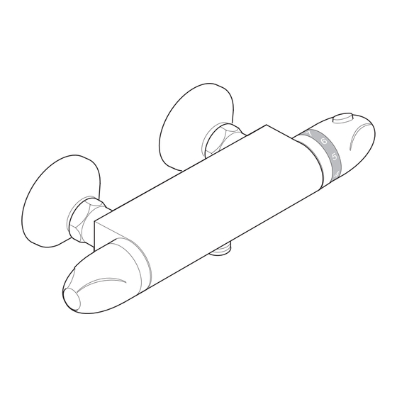
- Page 1 MIRA CODA THERMOSTATIC SHOWER VALVE Installation & User Guide These instructions are to be left with the user...
- Page 2 PATENT APPLICATION GB 2 407 138A...
-
Page 3: Specifications
Installations must comply with the requirements of UK Water Regulations/Bye- laws (Scotland), Building Regulations or any particular regulations and practices, specifi ed by the local water supplier. The Mira Coda is supplied and designed to operate with Mira L11 shower fi ttings. Pressure Range •... -
Page 4: Installation
INSTALLATION General The installation, commissioning and maintenance must be carried out according to instructions supplied, and must be conducted by qualifi ed or competent person. Before starting installation, ensure that all site requirements correspond to information given in the SPECIFICATION section. DO NOT install product in a position where it could become frozen. - Page 5 Solid Wall Installation For installation onto a stud partition or laminated panel wall, or onto unfi xed rear- entry pipework, refer to the next section: Stud Partition, Laminated Panel, or Unfi xed Rear-entry Pipework Installation. 1/2" BSP Female Make sure that the pipework is set Offset Connector Connector at the correct distance apart and...
- Page 6 Caution! Ensure supply pipework is fl ushed before installing the shower valve. Sealing Washer Assemble the shower valve with a sealing washer in each inlet and attach to the offset connectors. Tighten the nuts using a suitable spanner. Connect the shower fi ttings to the shower valve outlet.
- Page 7 Apply suitable thread sealant (not Mounting Bracket supplied) and attach the offset Offset Pipework connectors to the pipework in the Connector wall. Make sure that the connectors are level and set at the correct distance apart. Wall Spanner Flats Tighten the connection to the pipework while holding the offset connectors in place using a spanner on the spanner fl...
- Page 8 COMMISSIONING Setting the Maximum Temperature The Mira Coda Thermostatic Mixer has been preset to approximately 41°C under ideal conditions at the factory, which is appropriate for most systems. However, site conditions and personal preference may make it necessary to reset this temperature.
- Page 9 Insert a small screwdriver into the notch and pry off the cover plate. Unscrew the fi xing screw. Remove the temperature selector knob without disturbing the stop Fixing Screw assembly. Temperature Selector Knob Cover Plate Replace the temperature selector knob so that the 7 mark is level with the shoulder on the stop assembly .
-
Page 10: Operation
OPERATION Adjusting the Temperature The temperature is controlled by rotating the temperature selector knob. For safety reasons, the temperature is limited by a stop. To obtain a higher temperature, press the override button on the temperature selector knob and continue to rotate the knob. Adjusting the Flow The fl... -
Page 11: Fault Diagnosis
FAULT DIAGNOSIS Read the section: Important Safety Information fi rst. Provided that the Mira Coda has been correctly installed and is operated in accordance with the instructions contained in this guide, diffi culties should not arise. If any maintenance is required then it must be carried out by a competent tradesperson for whom the fault diagnosis chart and maintenance instructions are provided. - Page 12 Symptom Cause / Rectifi cation Drip from handset. A small amount of water may be retained in the fi tting after the shower control has been turned off. This may drain over a few minutes. This is quite normal. Changing the angle of the shower fi tting may vary the draining time.
-
Page 13: Maintenance
Cleaning The Mira Coda should be cleaned using a mild washing up detergent or soap solution, rinsed and then wiped dry with a soft cloth. Warning! Many household cleaners contain abrasive and chemical substances,... - Page 14 Maintaining the Non-Return Valves The non-return valves are located in the valve body, and are accessible through the inlet connectors. Caution! Ensure that the non-return valves are installed correctly to prevent crossfl ow or malfunction of the valve. With the water supplies turned off and the thermostatic mixer removed, remove the washer, the circlip and the fi...
- Page 15 SPARES 456.29 1630.045 Wall Mounting Temperature Knob Bracket Assembly 1630.041 Offset Connector Kit 1630.043 1630.042 Thermostatic Non Return Valve Cartridge 1630.049 1630.044 Filter Washer Temperature Stop 1630.047 Flow Knob Assembly 1630.048 Outlet Connector 1630.046 Flow Cartridge...
-
Page 16: Customer Service
CUSTOMER SERVICE UKAS 1065367-W2-A © Kohler Mira Limited, August 2006... - Page 17 Pdf Supplied By http://www.plumbworld.co.uk/...
Need help?
Do you have a question about the CODA and is the answer not in the manual?
Questions and answers