Table of Contents
Advertisement
Quick Links
Download this manual
See also:
User Manual
Advertisement
Table of Contents

Related Manuals for Albrecht TECtalk


Summary of Contents for Albrecht TECtalk
- Page 1 SERVICE MANUAL 2-WAY PORTABLE HANDHELD PMR RADIO TECtalk Jan. 2000...
-
Page 2: Table Of Contents
5.3 Transmitter 6 CHANNEL DATA 1. GENERAL GENERAL TECtalk is a minimum sized two-way portable handheld radio. The frequency range is 446.00625 ~ 446.09375MHz, 8 UHF operating channels according to European PMR 446 international agreement are available. 1.2 CHARACTERISTICS AND FEATURES a) All active devices in this radio are semiconductors and high density IC. -
Page 3: Specification
e) The radio is shipped with fixed (non-detachable) rubber duck antenna and belt clip and carrying strip. It comes without batteries. Other equipment is optional. 2. SPECIFICATION 2.1 GENERAL SPECIFICATIONS a) Frequency Range : 446.00625 ~ 446.09375 MHz b) Output Impedance : 50Ω unbalanced c) Modulation Type : 8K0F3E d) Communication Mode : semi-duplex e) Channel Capacity : 8 channels... -
Page 4: Operation
12) IF : 1'st IF = 21.7MHz 2'nd IF = 450kHz 13) Local Frequency : 1st Local Frequency = fc - 21.7MHz 2nd Local Frequency = 21.25MHz 3. OPERATION 3.1 Push Buttons and Controls... -
Page 5: Icons On Lcd
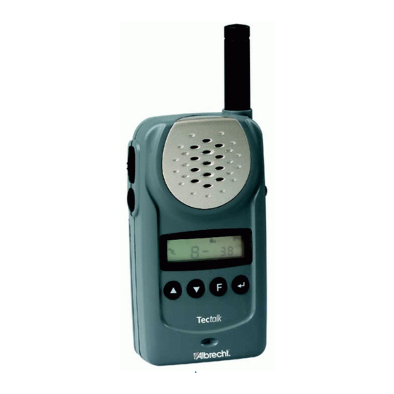
1) Battery Door 2) Monitor Button 3) Detachable Belt Clip 4) Push-To-Talk (PTT) Button 5) Antenna 6) External Mic / Speaker 7) Built-in Speaker 8) LCD Panel 9) Built-in Microphone 10) Up Button & Volume Control 11) Down Button & Volume Control 12) Function Button 13) Power On/Off &... - Page 6 Appears in the auto scan mode or when the auto scan mode is activated. 5) Dual Watch Scan Indicator Appears in dual watch scan mode or when the dual watch scan mode is activated. 6) Key Lock Indicator Blinks in auto lock selection mode or when the key lock is activated.
-
Page 7: Key Functions
12) Large Segment Display Indicates the channel number in use at the normal mode. When the Function Button is pressed, it displays the function menu in sequence: CH / SC / dW / UO / Udt / ALo / CAL / ton 13) Small Segment Display Displays the CTCSS tone option at the normal mode. - Page 8 1) Short Touch In the standby mode, press this button briefly to move to the next higher main volume level. In the function edit mode, press briefly to shift from the current option in each submenu to the next option in the same submenu. 2) Long Touch Pressing this button for more than 1.5 seconds will allow you to navigate at a more rapid rate through different volume level in the standby mode...
-
Page 9: Setting And Operation
3.4.1 BASIC CHANNEL SELECTION In order to communicate with other PMR units, both you and the receiving party must be on the same channel. Tectalk has 8 channels (1-8) as indicated by the large digits in the LCD Display Panel (#8). - Page 10 To access the Auto Channel Scan menu, press the Function Button (#12) until the auto channel icon blinks and SC appears in the LCD Panel (#8). Press the Up Button (#10) or the Down Button (#11) to choose scanning up or down from the current channel number.
- Page 11 3.4.6 VOX RECOVERY TIME SELECTION MODE This allows the response characteristics of the VOX function to be precisely adjusted to suit individual needs. To access the VOX Recovery Time Selection menu, press the Function Button (#12) until Udt appears in the LCD Panel (#8) with the VOX icon blinking.
-
Page 12: Adjustment
Check the voltage between TP & GND in digital volt meter. c) Then set the low channel of TECtalk the lowest frequency. d) After pressed PTT key of TECtalk , trim VC1 for adjusting the lowest frequency of Tx channel to DC 1.5V in the voltage of TP1. -
Page 13: Receiver
b) Audio Response Connect AF oscillator to Mic terminal and then firm the audio level that doesn't distortion the wave of oscilloscope in the frequency range, 300Hz to 3kHz. Check the audio level for 300Hz to 3kHz based on frequency standard, 1kHz. -
Page 14: Receiver Test
c) Signal generator Adjustment for RX sensitivity test 1) Adjust SSG to channel frequency. 2) Adjust modulation frequency, 1kHz to modulation degree, 1.5 kHz. 3) After adjusting the frequency of SSG to channel frequency, set RF level to -47dBm. d) Check and adjust Squelch sensitivity 1) Set the standard channel. - Page 15 ⓐ Battery could completely be discharged. ⓑ Battery cell wrong inserted? ⓒ Contact problem between Battery and Radio? ② Fail to transmit ⓐ Run out of battery or charge problem. ⓑ Fault of PTT key ⓒ Fault of Q4, Q5. ③Transmitter works but frequency is unmatched ⓐ...
-
Page 16: Description Of Radio Circuit
ⓓ SF1 SAW filter fail. ⓔ VCO problem. ④ Squelch does not work ⓐ U12 problem. ⓑ Control logic problem. 5. DESCRIPTION OF RADIO CIRCUIT 5.1 Frequency synthesizer Frequency synthesizer consists of VCO, PLL IC(built in PRESCALER) and loop filter. a) VCO VCO is composed of ONE VCO. - Page 17 a) Rx/Tx Conversion Circuit Rx signal goes to Rx/Tx conversion circuit through FIXED antenna connector, low pass filter(L5,L6,L7,C42,C43,C46,C47) and receiver resonance circuit composed of L8,C1. When transmitting, voltage through R25,L12,D6 supplies, D7 of receive input is short and Tx is on condition. When PIN diode is off in condition of Rx, L8 and C1 resonate serially and make impedance matching at receiver bandpass filter.
-
Page 18: Transmitter
Squelch threshold is controlled by Resistor R18,C31,R15 f) Audio Amplifier Demodulated audio signal enters to pin2 of U4. After above signal is amplified in U4 the audio output for the speaker is reached at pin 5 (through C220). 5.3 Transmitter When Tx starts with pressing PTT switch, VCO output amplifies through Q4,Q5 transmits by antenna through low pass filter. - Page 19 © Copyright Albrecht Electronic GmbH & Jcom Ltd, Jan. 2000 Albrecht Electronic GmbH Dovenkamp 11 22952 Lütjensee All service documents can be downloaded for service purpose from: http://www.albrecht-online.de Service-Hotline: (+49) 4154 849 180 Service-Fax: (+49) 4154 849 288 E-mail: service@albrecht-online.de...
Need help?
Do you have a question about the TECtalk and is the answer not in the manual?
Questions and answers