
Related Manuals for VarTech Systems VT121XA4


Summary of Contents for VarTech Systems VT121XA4
-
Page 1: Lcd Monitors
Solutions for Demanding Applications All Weather Series LCD Monitors VT121XA4 · VT121XB4 User’s Guide VT121 All Weather User’s Guide 150-183... -
Page 2: Table Of Contents
Read these instructions completely before attempting to operate your new LCD Color Display. Table Of Contents Page Page Section 1 Introduction Section 4 Touchscreen 1.0 Overview 4.1 Touch Screen Introduction 1.1 VT121 General Features 4.2 Touch Screen Installation 1.2 Product Safety Precautions Section 2 Display Setup Section 5 Troubleshooting 2.1 Inspection... -
Page 3: Section 1 Introduction
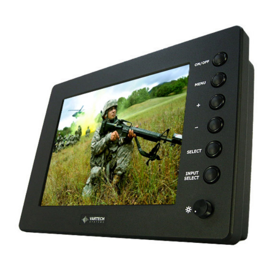
INTRODUCTION SECTION 1 1.1 Overview VarTech All-Weather series includes waterproof, totally sealed, IP67 NEMA 6 LCD displays. These high resolution, sunlight readable LCD displays provide exceptional clarity, viewing angles, extensive operational temperatures (-40°C to +70°C), IP67 (NEMA 6) protection, and offer durable, 5-Wire, resistive touch screens. 1.2 VT121 General Features IP67 Fully Enclosed LCD Rugged Machined 6061 T6 Aluminum Enclosure... -
Page 4: Section 2 Display Setup
DISPLAY SETUP SECTION 2 2.1 Inspection of your VT121 All Weather Display The Vartech VT121 All Weather display is supplied with different accessories depending on the model configuration purchased. Verify that the display and accessories are what were ordered. Contact your Vartech salesperson should there be any discrepancies. - Page 5 4. Loosen the socket and slip the ball into the socket. Secure in place by tightening the socket. Mechanical Drawings Model Description Page(s) VT121XA4/XB4 VESA/RAM Mount Drawing VT121XA4/XB4 Flush Mount 2.5 Input Video Connections VT121 All Weather User’s Guide 150-183...
-
Page 6: Section 3 Getting Started
Typical Input Assembly Connect to an Analog Video Source All of the monitors support analog video. Your monitor is shipped with a high-quality analog video cable. Use this video cable to connect a computer to the monitor. Follow these steps to connect the monitor to an analog video source. 1. -
Page 7: Adjusting The Display
SECTION 3 3.1 Adjusting the display Set the monitor type The VT121XA/XB monitors are not plug n play compatible and require initial setup to begin operation 1. Ensure video and power cables are connected and secure and connected to the source 2. - Page 8 For Models with Single Analog Video, Single Digital Video, or NTSC/PAL Selection page Select input source Select input source to Analog RGB Select input source to DVI Select input source to S-Video 1 Select input source to Composite 1 Select input source to S-Video 2 (No function now) Select input source to Composite 2 (No function now) Auto Source Seek ON –...
- Page 9 Brightness Increase/decrease brightness level. Press – or + (- + ) Total : 256 steps Contrast Increase/decrease panel contrast level. Press – or + (- + ) Total : 192 steps Saturation* Increase/decrease hue level. Press – or + (- + ) Total : 256 steps Hue* Increase/decrease saturation level...
- Page 10 OSD Timeout : 0 / 10 / 20 / 30 / 40 / 50 / 60 seconds (Always on when set to 0) Press – or + (- OSD menu horizontal position Press – or + (- OSD menu vertical position Press –...
- Page 11 Picture : Volume Increase/decrease volume level, total 31 steps Brightness Increase/decrease panel brightness level, total: 100 steps Contrast Increase/decrease panel contrast level, total: 100 steps Hue * Increase/decrease Hue level, total: 100 steps Saturation * Increase/decrease saturation, total: 100 steps Sharpness Increase/decrease sharpness, total: 15 steps Aspect Size ...
- Page 12 appendix IV) Manual Clock Adjust the image horizontal size Manual Phase Fine tune the data sampling position (adjust image quality) Auto Source Seek : OFF / ON ON – Auto source select always enable OFF – Disable auto source select function Auto Power : OFF / ON ON –...
- Page 13 Hot key 2 : Brightness / Contrast / Input / Aspect / Volume Reset to Factory Defaults Factory Defaults Reset Color Gain DDC Updates ** : FUNCTION IN VIDEO MODE ONLY # : DISPLAY AND FUNCTION IN VGA MODE ONLY Adjust the Brightness Use the dimming potentiometer located on the front bottom right corner of the display to adjust the brightness level of the LED backlights.
-
Page 14: Section 4 Touchscreen
Armor resistive touch. 4.2 Installation All Vartech Systems displays configured with a touch screen are supplied with a CDROM which includes user manuals, application software, and drivers for various operating systems. Insert the supplied CDROM into a CDROM drive and follow the installation instructions that will appear on the screen. -
Page 15: Section 5 Troubleshooting
TROUBLESHOOTING SECTION 5 General A general guide to troubleshooting a flat panel display system it is worth considering the system as separate elements, such as: Controller (jumpers, PC settings) Panel (controller, cabling, connection, panel, PC settings) Backlight (inverter, cabling,) Cabling Computer system (display settings, operating system) Through step by step cross checking with instruction manuals and a process of elimination to isolate the problem it is usually possible to clearly identify the problem area. -
Page 16: Section 6 Maintenance
MAINTENANCE SECTION 6 6.1 Cleaning Occasionally clean the display panel and cabinet with a soft cloth dampened (not soaked) with a mild (non-abrasive) glass cleaner. Keep turning a fresh side of the cloth toward the screen surface to avoid scratching it with accumulated grit. -
Page 17: Specifications
SPECIFICATIONS ENGINEERING SPECIFICATIONS – VT121XA Panel Size 12.1” (31cm) Type Active Matrix Color Thin Film Transistor (TFT) Native Panel Resolution SVGA Pixel Format 800 (H) x 600 (V) Pixel Pitch 0.3075 (H) x 0.3075 (V) mm Pixel Arrangement RGB (Red dot, Green dot, Blue dot) vertical stripe Dot Pitch 0.1025 (H) x 0.3075 (V) mm 9.685”... -
Page 18: Specifications
SPECIFICATIONS ENGINEERING SPECIFICATIONS – VT121XB Panel Size 12.1” (31cm) Type Active Matrix Color Thin Film Transistor (TFT) Native Panel Resolution Pixel Format 1024 (H) x 768 (V) Pixel Pitch 0.240 (H) x 0.240 (V) mm Pixel Arrangement RGB (Red dot, Green dot, Blue dot) vertical stripe Dot Pitch 0.080 (H) x 0.240 (V) mm 9.676”... - Page 19 VT121 All Weather User’s Guide 150-183...
- Page 20 VT121 All Weather User’s Guide 150-183...
- Page 21 Power Cable Diagram The RED wire with the +V would be connected to the +DC input voltage (like 12VDC or 24VDC) The BLACK wire with the –V would be connected to the DC input return. Considering a DC battery, the +V is the positive terminal on the battery while the –V is the negative terminal on the battery.
- Page 22 VARTECH SYSTEMS INC. HEADQUARTERS 6399 Amp Drive, Clemmons, NC 27012 Toll-Free: 800.223.8050 International Phone: 001.225.298.0300 Fax: 225.297.2440 E-mail: sales@vartechsystems.com www.vartechsystems.com VT121 All Weather User’s Guide 150-183...
Need help?
Do you have a question about the VT121XA4 and is the answer not in the manual?
Questions and answers