Table of Contents
Advertisement
Quick Links
Solutions for Demanding Applications
VarTech Systems Inc.
Industrial CRT and Flat Panel Displays
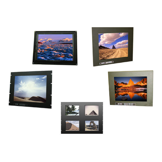
VT121 ColorVue Series
12.1" Flat Panels
VT121CC · VT121PC
VT121RC · VT121WC
VT121PCQ
User's Guide
Read these instructions completely before attempting to operate your new Color Display
.
VT121 ColorVue Series User Guide
150-033
Advertisement
Table of Contents

Related Manuals for VarTech Systems VT121CC


Summary of Contents for VarTech Systems VT121CC
- Page 1 Solutions for Demanding Applications VarTech Systems Inc. Industrial CRT and Flat Panel Displays VT121 ColorVue Series 12.1” Flat Panels VT121CC · VT121PC VT121RC · VT121WC VT121PCQ User’s Guide Read these instructions completely before attempting to operate your new Color Display...
-
Page 2: Table Of Contents
Table Of Contents Page Page Section 1 Section 7 Warnings and Cautions The Display Controls 7.1 Display Controls Section 2 7.2 Screen Adjustment Operation Procedure FCC Statement Section 8 Section 3 The Screen Adjustment Product Safety Precautions 8.1 Main Menu 8.2 OSD Adjusting and Controls 10-11 8.3 How to use Autotune Adjustment... -
Page 3: Warnings And Cautions
Section WARNINGS AND CAUTIONS WARNINGS AND CAUTIONS RISK OF ELECTRIC SHOCK! DO NOT OPEN!!! WARRANTY VOID IF CASING IS REMOVED. CAUTION: To reduce the risk of electric shock, do not remove cover (or back). No user serviceable parts inside. Refer servicing to qualified technician. -
Page 4: Fcc Statement
Section FCC STATEMENT FCC STATEMENT Federal Communications Commission (F.C.C.) Statement This equipment has been tested and found to comply with the limits for a Class A digital device, pursuant to Part 15 of the FCC Rules. These limits are designed to provide reasonable protection against harmful Interference in a industrial installation. -
Page 5: Product Safety Precautions
Section PRODUCT SAFETY PRECAUTIONS PRODUCT SAFETY PRECAUTIONS Ensure that sufficient space is available around the display to provide the circulation ⇒ necessary for cooling. Ensure that the ambient air temperature will not exceed the specified maximum ⇒ temperature. Do not attempt to service this display yourself. The rear chassis has a seal so that non ⇒... -
Page 6: Hardware Installation
4.1 Unpacking and setting up your display Your LCD monitor package will consist of the components listed below. Open shipping container and lay all components on a flat clean surface. VT121CC, VT121RC, VT121PC, VT121WC, or VT121PCQ LCD Monitor ⇒ 15-PIN D-sub Video cable ⇒... -
Page 7: Video Input Pin Assignment
4.3 Video Input Pin Assignment This section describes the pin assignment of the LCD’s video connector. Pin assignments for the HD15 video connector Connection Connection Red Video No Connection Green Video Ground Blue Video No Connection No Connection DDC Data Ground Horizontal Sync Red Video Ground... -
Page 8: Touch Screen
Installation All Vartech Systems displays configured with a touch screen are supplied with a CDROM which includes user manuals, application software, and drivers for various operating systems. Insert the supplied CDROM into a CDROM drive and follow the installation instructions that will appear on the screen. -
Page 9: The Display Timing
Section DISPLAY TIMING DISPLAY TIMING The following table lists the better display quality modes that the LCD monitor provides. If the other video modes are input, the monitor will stop working or display unsatisfactory picture quality. VESA MODES Horizontal Vertical Nominal Nominal Nominal... -
Page 10: Section 6 The Display Timing
The Display Timing Cont. IBM MODES Horizontal Vertical Nominal Nominal Nominal Pixel Mode Resolution Total Frequency Frequency Clock (MHz) ±0.5KHz ±1Hz 640 x 350@70Hz 800 x 449 31.469 70.086 25.175 640 x 480@60Hz 800 x 449 31.469 70.086 25.175 800 x 600@56Hz 900 x 449 31.469 70.087... -
Page 11: Display Controls
Section DISPLAY CONTROLS DISPLAY CONTROLS 7.1 Display Controls Button Description Function Press the power key to turn the monitor on. Power Press it again to turn the monitor off (Located on the rear of the monitor) Enter or exit the OSD adjustment menu. MENU MENU Exit from the submenu back to the previous menu. -
Page 12: Main Menu
Section SCREEN ADJUSTMENT SCREEN ADJUSTMENT 8.1 Main Menu The OSD main menu (Figure 8-1) is displayed on screen when the MENU key pressed. The OSD menu is a combination of graphic and text display. The selected item is draw in red color. In the last item press LEFT or RIGHT key to exit OSD. -
Page 13: Osd Adjusting And Controls
8.2 OSD Adjusting and Controls OSD Functions Symbol Description Function RESOLUTION Display the picture model. AUTOTUNE & Autotune the parameters or Recall the factory setting of this mode. RECALL Press LEFT key will EXIT and not save the parameters you adjust. EXIT Press RIGHT key will exit an save the parameters and adjust. -
Page 14: Osd Adjusting And Controls
8.2 OSD Adjusting and Controls Cont. OSD Functions Symbol Description Function Phase is used to adjust the Analog to Digital sample pixel clock, PHASE adjust Phase can reduce horizontal noise. A slider with current value is displayed. Track is used to adjust the Analog to Digital sample pixel clock, TRACK adjust Track can reduce horizontal noise. -
Page 15: How To Use Autotune Adjustment
8.3 How to use Autotune Adjustment The Autotune is a new design OSD adjustment item. We will tell you how to use Autotune adjust- ment below. The adjustment of Autotune: This function can tune the parameters of Phase, Track, Frequency, H-Position and V-Position. -
Page 16: Troubleshooting Tips
Section TROUBLESHOOTING TROUBLESHOOTING Troubleshooting Tips Problem Troubleshooting Tip 1. Check that power cord of the computer has been connected No image on display screen securely into wall outlet or grounded extension cable or strip. 2. Check that power switch of the Display has been pressed. 3. -
Page 17: Cleaning & Maintenance
Section CLEANING AND MAINTENANCE CLEANING AND MAINTENANCE Cleaning Occasionally clean the display panel and cabinet with a soft cloth dampened (not soaked) with a mild (non-abrasive) glass cleaner. Keep turning a fresh side of the cloth toward the screen surface to avoid scratching it with accumulated grit. Note: The solvent should be applied only to the cloth, and not directly on the monitor screen. -
Page 18: Mechanical Drawings
12.1” ColorVue Panel Mount Mechanical Drawing VT121RC 12.1” ColorVue Rack Mount Mechanical Drawing VT121WC 12.1” ColorVue Wall Mount Mechanical Drawing VT121CC 12.1” ColorVue Chassis Mount Mechanical Drawing VT121PCQ 12.1” ColorVue Quad Panel Mechanical Drawing VT121 ColorVue Series User Guide 150-033... -
Page 19: Specifications
Section SPECIFICATIONS SPECIFICATIONS VT121 Specifications LCD panel type 12.1” TFT Resolution VGA to SVGA 800 x 600 Max. Pixel dimension 0.3075mm LCD display color 262,144 Colors OSD control H/V Position, Clock, Phase, Auto Config, Recall, Contrast, Brightness, Exit, Track, Resolution Manual Control Menu, Select, Adjust ( ) Power... - Page 20 VARTECH SYSTEMS INC. HEADQUARTERS 11529 Sun Belt Ct. Baton Rouge, Louisiana 70809 Toll-Free: 800.223.8050 International Phone: 001.225.298.0300 Fax: 225.297.2440 E-mail: sales@vartechsystems.com www.vartechsystems.com 150-033-007 09.10.04 VT121 ColorVue Series User Guide 150-033...
Need help?
Do you have a question about the VT121CC and is the answer not in the manual?
Questions and answers