Bunn Axiom Series Service & Repair Manual
Hide thumbs
Also See for Axiom Series:
- User manual ,
- Technical training manual (35 pages) ,
- Programming manual (18 pages)

Subscribe to Our Youtube Channel
Related Manuals for Bunn Axiom Series


Summary of Contents for Bunn Axiom Series
- Page 1 SERVICE & REPAIR MANUAL BUNN-O-MATIC CORPORATION POST OFFICE BOX 3227 SPRINGFIELD, ILLINOIS 62708-3227 PHONE: (217) 529-6601 FAX: (217) 529-6644 39132.0000E 04/12 ©2008 Bunn-O-Matic Corporation...
- Page 2 BUNN’S SOLE OPTION AS SPECIFIED HEREIN, TO REPAIR, REPLACEMENT OR REFUND. In no event shall BUNN be liable for any other damage or loss, including, but not limited to, lost profi ts, lost sales, loss of use of equipment, claims of Buyer’s customers, cost of capital, cost of down time, cost of substi- tute equipment, facilities or services, or any other special, incidental or consequential damages.
-
Page 3: Table Of Contents
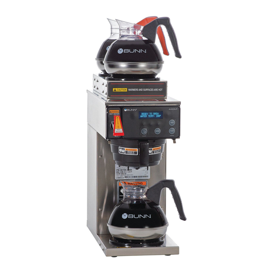
INTRODUCTION This equipment will brew a half-gallon batch of coffee into an awaiting dispenser. It can be easily confi gured for 120V 15 amp, 120/208V 20 amp or 120/240V 20 amp. The brewer may have a hot water faucet for allied beverage use. It is only for indoor use on a sturdy counter or shelf. -
Page 4: Troubleshooting
TROUBLESHOOTING A troubleshooting guide is provided to suggest probable causes and remedies for the most likely problems encountered. If the problem remains after exhausting the troubleshooting steps, contact the Bunn-O-Matic Technical Service Department. • Inspection, testing, and repair of electrical equipment should be performed only by qualifi ed service person- nel. - Page 5 TROUBLESHOOTING (cont.) REFILL CIRCUIT PROBLEM PROBABLE CAUSE REMEDY Will not refi ll Press OFF/ON switch on control 1. Power off to brewer panel to determine if power is ON. Make sure water is ON. 2. Water shut off Brewer has shut down due to mal- 3.
- Page 6 TROUBLESHOOTING (cont.) HEATING CIRCUIT PROBLEM PROBABLE CAUSE REMEDY Water does not heat to proper 1. Display's error message Brewer has shut down due to mal- temperature function. See Diagnostics. IMPORTANT: Make sure no tem- perature tests are taken before 2. Water not touching main (short) Remove level probe and grommet.
- Page 7 TROUBLESHOOTING (cont.) BREWING CIRCUIT PROBLEM PROBABLE CAUSE REMEDY Brew cycle will not start 1. Display's error message Brewer has shut down due to mal- function. See Diagnostics. 2. No water Water lines and valves to the brewer must be open. 3.
- Page 8 Refer to Initial Set-up instructions. 3. Filter type BUNN® paper fi lters must be used for proper extraction. 4. Coffee grind A fi ne drip or grind must be used for proper extraction.
-
Page 9: Diagnostics
DIAGNOSTICS MESSAGE PROBABLE CAUSE REMEDY "CHECK SPRAYHEAD FOR LIME" - 1. Lime buildup in sprayhead Clean sprayhead "CHECK FITTINGS FOR LIME" 2. Lime buildup in brew valve Clean valve 3. Lime buildup in brew tank Clean tank "WARNING INACCURATE FLOW" 1. -
Page 10: Technician Programming Reminders
TECHNICIAN PROGRAMMING REMINDERS REVERSE REVERSE FORWARD FORWARD AXIOM VERSION ##.## VIEW ASSET/SERIAL # ENTER PROGRAMMING ACCESSING PROGRAM MODES Press and hold the right hidden switch. The longer you press it, the higher the level you can access. EXAMPLE: Pressing for a couple seconds enters Level 1. Continuing to press for approximately 5 seconds will access Level 2. -
Page 11: Access
COMPONENT ACCESS This section provides procedures for testing and replacing various major components used in this brewer should service become necessary. Refer to Troubleshooting for assistance in determining the cause of any problem. WARNING - Inspection, testing, and repair of electri- cal equipment should be performed only by qualifi... -
Page 12: Control Board
CONTROL BOARD 5. Remove the two screws and two nylon washers securing the control board to the front face plate. 6. Tilt the control board inward to clear the display section. 7. Place the bottom edge of the new control board in the two cradles, tilt the board forward, and secure with the two screws and nylon washers to the front face plate. - Page 13 FACEPLATE REMOVAL 8. Remove the two screws and two nylon washers securing the control board to the front face plate. Faceplate Removal and Replacement: 9. Place the bottom edge of the new control board in 1. Disconnect brewer from power source. the two cradles and secure with the two screws and 2.
-
Page 14: Face Plate
MEMBRANE SWITCH you can test it with an ohmmeter or continuity tester. Refer to the schematic to trace the appropriate pins. NOTE: Pin 1 is the static shield & will not provide a reading to the other pins. There are two commons in this circuit, pins 9 &... -
Page 15: Brew Valve
BREW VALVE observed, brew valve is defective. Replace valve and test again to verify repair. If voltage is not present as described, refer to Wir- ing Diagrams and check the brewer wiring harness. Also check the control board and switch for proper operation. -
Page 16: Optional Brew Valve
OPTIONAL BREW VALVE (ON SELECT MODELS) observed, brew valve is defective. Replace valve and test again to verify repair. If voltage is not present as described, refer to Wir- ing Diagrams and check the brewer wiring harness. Also check the control board and switch for proper operation. -
Page 17: Level Probes
LEVEL PROBE SYSTEM 2. A high reading (approximately 255) indicates water is not touching, or not conductive enough to ground the circuit. A low reading (0-2) indicates the probe is grounded. Removal and Replacement: 1. Disconnect the brewer from the power source and allow tank to cool. - Page 18 REFILL VALVE - EARLY MODELS If the sound is not heard as described, proceed to # 5. 5. Disconnect the brewer from the power source. 6. Check for continuity across the refi ll valve coil terminals. If continuity is not present as described, replace the refi...
- Page 19 REFILL VALVE - LATER MODELS # 5. 5. Disconnect the brewer from the power source. 6. Check for continuity across the refi ll valve coil terminals. If continuity is not present as described, replace the refi ll valve. If continuity is present as described, there could be some debris in the valve.
-
Page 20: Tank Heaters
TANK HEATERS Location: The tank heaters are located inside the tank and secured to the tank bottom. Test Procedures: 2268W 1425W 1. With a voltmeter, check voltage across the white Large Small wire (120V Models) or red wire (120/208-240V Dia. Dia. -
Page 21: Limit Thermostat
LIMIT THERMOSTAT THERMAL CUT OFF (230V MODELS ONLY) FIG. 21-1 TCO CHECK Location: The TCO's are located under the tank at the heater connections. FIG. 21-2 LIMIT THERMOSTAT Test Procedures: 1. Disconnect the brewer from the power source. 2. Disconnect the TCO from the tank heater. Location: 3. -
Page 22: Blanket Warmer
BLANKET WARMER 4. Check the resistance across the two terminals on the blanket warmer. Refer to chart below. If resistance is to specifi cation, reconnect the two wires to the blanket warmer. If resistance is not to specifi cation, replace the blanket warmer. -
Page 23: Temperature Probe
TEMPERATURE PROBE If resistance is to specifi cation, replace the control board. If resistance is not to specifi cation, replace the tem- perature probe. Removal and Replacement: 1. Disconnect the brewer from the power source. 2. Disconnect the two pin connector from J9 on control board. -
Page 24: Warmer Elements
WARMER ELEMENTS wires to the warmer element. If resistance is not to specifi cation, replace the warmer element. Removal and Replacement: 1. Remove the three #4-40 screws securing the warmer assembly to the brewer. 2. Lift the warmer assembly from the brewer. 3. -
Page 25: Voltage Selector Switch
VOLTAGE SELECTOR SWITCH Removal and Replacement: 1. Disconnect the brewer from the power source. 2. Disconnect the wires from the power switch. 3. Remove the switch mounting screws from the left side of trunk. 4. Install new switch in trunk with the two 6-32 x ¼˝ mounting screws. -
Page 26: Power Switch
MASTER ON/OFF SWITCH Removal and Replacement: 1. Disconnect the brewer from the power source. 2. Disconnect the wires from the power switch. 3. Remove the switch mounting screws from the left side of trunk. 4. Install new switch in trunk with the two 6-32 x ¼˝ mounting screws. - Page 27 PROGRAMMING FUNCTIONS LEVEL 3 - FLOW CHART ENTERING LEVEL 3 REVERSE FORWARD AXIOM VERSION ##.## CAL TEMPERATURE LP1 LP2 OZ 4.50 % LimeAdjust OFF NO SENSOR? YES DONE DONE SPRAY OZ/M: ##.# CALIBRATE FLOW ? AXIOM DONE VERSION ##.## 39132 062309 Page 27...
-
Page 28: Programming Level 3
PROGRAMMING - LEVEL 3 Allows technician to calibrate after probe and/or control board replace- CAL TEMPERATURE ment. Select "YES". NO SENSOR? YES NOTE: Tank temperature must be within range (192° - 208° F) VIDEO CLIP: Calibrate Temp Click - > Insert an accurate thermometer approximately 10˝... - Page 29 PROGRAMMING FUNCTIONS LEVEL 4 - FLOW CHART ENTERING LEVEL 4 REVERSE FORWARD AXIOM VERSION ##.## SERIAL # TYPE AXIOM AX00000000 AX00 VERSION ##.## DONE In case of board replacement, match the Data Plate information. SERIAL # TYPE AX00 - Standard Axiom with warmers AX00 AXAP - Axiom AirPot Server AXTN - Not used...
- Page 30 39132 041708 Page 30...
- Page 31 39132 041708 Page 31...
- Page 32 39132 041708 Page 32...
- Page 33 39132 041708 Page 33...
-
Page 34: Wiring Diagrams
LEVEL PROBE “CONTROL” (LONG) OPTIONAL DUAL TOP WARMER ASSY OPTIONAL DUAL TOP WARMER ASSY BRN/BLK REAR 120V AC 2 WIRE 120/208V AC 3 WIRE BLU/BLK 120/240V AC 3 WIRE FRONT SINGLE PHASE 29077.0006D 02/09 ©2006 BUNN-O-MATIC CORPORATION 39132 052709 Page 34... - Page 35 39132 041708 Page 35...
-
Page 36: Schematic Wiring Diagram
START BREW 120V AC 2 WIRE + GND LEFT HIDDEN LEVEL PROBE (LONG) RIGHT HIDDEN 120/208V AC 3 WIRE + GND “DIGITAL” “BREWER” 120/240V AC 3 WIRE + GND “CONTROL” SINGLE PHASE 29077.0008B 01/07 ©2006 BUNN-O-MATIC CORPORATION 39132 041708 Page 36... - Page 37 29077.0012 obsolete, refer to 29077.0022 39132 071111 Page 37...
- Page 38 39132 041708 Page 38...
- Page 39 39132 041708 Page 39...
- Page 40 LEFT REAR TOP FRONT J9-1 TOP REAR RIGHT FRONT LEVEL PROBE (SHORT) RIGHT REAR START BREW LEFT HIDDEN LEVEL PROBE (LONG) RIGHT HIDDEN “DIGITAL” “BREWER” “CONTROL” 100V AC 2 WIRE 29077.0016B 11/09 ©2008 BUNN-O-MATIC CORPORATION SINGLE PHASE 39132 120309 Page 40...
- Page 41 TOP REAR RIGHT FRONT LEVEL PROBE (SHORT) RIGHT REAR START BREW LEFT HIDDEN LEVEL PROBE (LONG) RIGHT HIDDEN “DIGITAL” “BREWER” “CONTROL” 230 VOLTS CE 2 WIRE + GND SINGLE PHASE 29077.0017A 10/08 ©2008 BUNN-O-MATIC CORPORATION 50 HZ 39132 041708 Page 41...
- Page 42 START BREW 120V AC 2 WIRE + GND LEFT HIDDEN LEVEL PROBE (LONG) RIGHT HIDDEN 120/208V AC 3 WIRE + GND “DIGITAL” “BREWER” 120/240V AC 3 WIRE + GND “CONTROL” SINGLE PHASE 29077.0018A 11/08 ©2008 BUNN-O-MATIC CORPORATION 39132 041708 Page 42...
- Page 43 START BREW J3-3 LEFT HIDDEN RIGHT HIDDEN J9-1 “DIGITAL” “BREWER” LEVEL PROBE “CONTROL” (SHORT) LEVEL PROBE (LONG) 120V AC 2 WIRE 120/208V AC 3 WIRE 120/240V AC 3 WIRE SINGLE PHASE 29077.0019A 03/09 ©2009 BUNN-O-MATIC CORPORATION 39132 041708 Page 43...
- Page 44 BREW STATION LEFT FRONT J3-3 LEFT REAR TOP FRONT J9-1 TOP REAR RIGHT FRONT LEVEL PROBE (SHORT) RIGHT REAR START BREW LEFT HIDDEN LEVEL PROBE (LONG) RIGHT HIDDEN t° “DIGITAL” “BREWER” “CONTROL” 29077.0020B 04/10 ©2009 BUNN-O-MATIC CORPORATION 39132 061710 Page 44...
- Page 45 39132 061710 Page 45...
- Page 46 N.O. WHI/GRN WHI/GRN WHI/BLU WHI/RED WHI/GRN WHI/GRN CONTROL SWITCH ASSY CONTROL SWITCH ASSY STATIC STATIC SHIELD SHIELD LEVEL PROBE (SHORT) LEVEL PROBE (SHORT) LEVEL PROBE (LONG) LEVEL PROBE (LONG) t° t° 29077.0023A 11/11 ©2011 BUNN-O-MATIC CORPORATION 39132 101310 Page 46...
- Page 47 J9-1 BREW “C” LEVEL PROBE (SHORT) START BREW J9-1 BEEPER LEFT HIDDEN LEVEL PROBE (LONG) RIGHT HIDDEN t° “DIGITAL” “BREWER” “CONTROL” 100-200 VOLTS 2 WIRE + GND SINGLE PHASE 29077.0025A 10/11 ©2011 BUNN-O-MATIC CORPORATION 50/60 HZ 39132 071111 Page 47...
- Page 48 39132 021512 Page 48...
Need help?
Do you have a question about the Axiom Series and is the answer not in the manual?
Questions and answers