Table of Contents
Advertisement
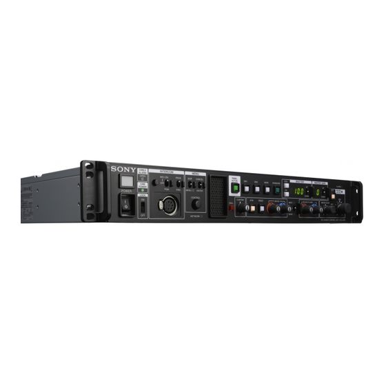
HD Camera Control Unit
The supplied CD-ROM includes operating instructions for the HXCU-D70 HD
Camera Control Unit (Japanese, English, French, German, Italian, Spanish and
Chinese versions) in PDF format. For more details, see "Using the CD-ROM
Manual" on page 7.
Operating Instructions
Before operating the unit, please read this manual thoroughly
and retain it for future reference.
HXCU-D70
© 2011 Sony Corporation
4-291-689-11 (1)
Advertisement
Table of Contents

Related Manuals for Sony HXCU-D70


Summary of Contents for Sony HXCU-D70
-
Page 1: Operating Instructions
4-291-689-11 (1) HD Camera Control Unit The supplied CD-ROM includes operating instructions for the HXCU-D70 HD Camera Control Unit (Japanese, English, French, German, Italian, Spanish and Chinese versions) in PDF format. For more details, see “Using the CD-ROM Manual” on page 7. - Page 2 The model and serial numbers are located at the rear. Record these numbers in the spaces provided below. Refer to For the customers in the U.S.A. them whenever you call upon your Sony dealer regarding this This equipment has been tested and found to comply with the product.
- Page 3 être amené à prendre des mesures appropriées. Pour les clients en Europe Le fabricant de ce produit est Sony Corporation, 1-7-1 Konan, Minato-ku, Tokyo, Japon. Le représentant autorisé pour EMC et la sécurité des produits...
- Page 4 Betreiber verlangt werden, angemessene Maßnahmen durchzuführen und dafür aufzukommen. Für Kunden in Europa Der Hersteller dieses Produkts ist Sony Corporation, 1-7-1 Konan, Minato-ku, Tokyo, Japan.Der autorisierte Repräsentant für EMV und Produktsicherheit ist Sony Deutschland GmbH, Hedelfinger Strasse 61, 70327 Stuttgart, Deutschland.
-
Page 5: Table Of Contents
Table of Contents Overview ..............6 Features ................6 System Configuration Example ........7 Using the CD-ROM Manual ..........7 Preparations .............. 8 Area Settings ..............8 CABLE COMPENSATION Settings ........ 8 Locations and Functions of Parts ......9 Front Panel ..............9 Rear Panel .............. -
Page 6: Overview
A camera control system with the HXC-D70 high resolution another, regardless of the cable length. HD color camera can be built up using just one Sony-standard multi-core cable (CCZ-A). Built-in wideband down converter... -
Page 7: System Configuration Example
• Adobe Reader Version 6.0 or higher If you have lost or damaged the CD-ROM, you can purchase a new one to replace it. Contact your Sony dealer or a Sony service If Adobe Reader is not installed, you can download it from the representative. -
Page 8: Preparations
CUSTOM PRESET WHITE BLACK/FLARE AUTO WHITE CALL BLACK AUTO NETWORK HD CAMERA CONTROL UNIT HXCU-D70 BLACK NETWORK HD CAMERA CONTROL UNIT HXCU-D70 LOCK switch LOCK switch POWER switch POWER switch Turn the power on. Turn the power on. The camera does not need to be connected to perform The camera does not need to be connected to perform this setting. -
Page 9: Locations And Functions Of Parts
MASTER BLACK WHITE CALL AUTO BLACK NETWORK HD CAMERA CONTROL UNIT HXCU-D70 l mn a Tally light • MIC/PGM (microphone/program) switch Turns on red to indicate a red tally signal is being received ON: Turns the headset microphone on. (such as when the picture from the camera connected to the OFF: Turns the headset microphone off. - Page 10 e PANEL ACTIVE button j MASTER GAIN control block Activates the control panel to control the camera connected to Controls the video output signal gain in response to the the CCU (panel active state). When the button is lit, the lighting of the subject.
- Page 11 q CUSTOM (custom volume) knob u IRIS/MASTER BLACK adjustment control block Controls the function assigned to the knob on the <FRONT MASTER BLACK (master black adjustment) knob PANEL 1> page in the CCU CONFIGURATION menu. Turning the knob adjusts the assigned function. EXT (lens extender) indicator See “VOLUME”...
-
Page 12: Rear Panel
VBS RETURN 1, 2 (VBS return video 1, 2) connectors high-resolution function to off to avoid image artifacts. (BNC type) • Use a Sony high-speed HDMI cable. IN: Inputs the VBS return video signals (2-system). m VBS 1, 2 (composite video signal 1, 2) connectors... - Page 13 o PIX (picture monitor output) connector (BNC type) Outputs a video signal for a picture monitor. It can also output a signal with superimposed character display. p SYNC (sync signal output) connector Outputs a sync signal for connection to the sync signal input connector of a waveform monitor or picture monitor.
-
Page 14: Status Display
Camera settings Status Display Page 1 The CCU system status can be monitored using a picture 1/ 20 00 OF F monitor connected to the PIX output. For information on monitoring and changing settings, see “Setup Menu” on page 17. Displaying the Status Screen The status screen is controlled using the knob and levers in N D: 1 F: 4. -
Page 15: System Status
System status Page 2 * Sy st em D ia g 2/ 3* 4 /1 3 *Syst em S t at us * 1 / 1 3 C AM ER A C ab le C on ne ct HXC-D 70 1 08 0/ 5 9. - Page 16 Page 2 PLD DE-MUX: DEMUX-PLD version PLD SY: SY-PLD version *Netw or k D ia g 2/ 3 * 7 / 1 3 PLD POST: POST-PLD version PLD HDMI: HDMI-PLD version CNS M od e : BR I GD E IIC: IIC bus control status CCU N o.
-
Page 17: Setup Menu
To change the displayed page Setup Menu Turn the CONTROL knob to move the pointer (,) to the page number, then press the CONTROL knob. The pointer (,) changes to a flashing question mark (?). The CCU system and peripheral settings can be checked and Flashing modified using a picture monitor connected to the PIX output. - Page 18 To enter a character string Some menu items require a character string input. Moving the pointer (,) to an item with a character string input and pressing the CONTROL knob displays a rectangular cursor and a list of selectable characters. Turning the CONTROL knob moves the cursor between characters.
-
Page 19: Menu Tree
Menu Tree SYSTEM OPERATION menu CCU CONFIGURATION menu OUTPUT SELECT OUTPUT COLOR BAR HD BAR GENLOCK PHASE REFERENCE MF CB GENLOCK SLOPE H STEP SD BAR COARSE BAR CHARA SC PHASE GRAY V PHASE BAR CHARACTER BAR CHARACATER SYNC OUT ALL CLEAR MULTI FORMAT FREQUENCY... - Page 20 DISPLAY MESSAGE ALARM JUMP MASTER GAIN ECS/SHUTTER ND FILTER IRIS EXTENDER DATE DATE/TIME TIME ZONE OTHERS REAR PREVIEW CABLE COMP FRONT PANEL 1 ASSIGNABLE/CUSTOM VOLUME VOLUME MODE IRIS M BLACK R/B BLACK R/B WHITE FRONT PANEL 2 VOLUME REL COEFF IRIS M BLACK R/B BLACK...
-
Page 21: Menu List
Menu List Note The following conventions are used in the menu list table. Settings column values (e.g. ON, OFF, 0): Default settings Execute by ENTER: Press the CONTROL knob or move the CANCEL/ENTER lever to the ENTER position to execute. SYSTEM OPERATION menu SYSTEM OPERATION Page name... - Page 22 SYSTEM OPERATION Page name Page No. Item Settings Description <OUTPUT FORMAT> SLOT NO 1-1&2 When CAMERA FORMAT is SDI OUTPUT 1/2 connector output format 1080/59.94i: 1080/59.94i, selection 525/59.94i Sequence of format options: When CAMERA FORMAT is 1: HD 720/59.94P: 720/59.94P, 2: SD 525/59.94i When CAMERA FORMAT is...
-
Page 23: Ccu Configuration Menu
CCU CONFIGURATION menu CCU CONFIGURATION Page name Page No. Item Settings Description <COLOR BAR> HD BAR BAR 16:9 (100%), BAR 16:9 HD output color bar settings (75%), SMPTE 16:9 (BLACK), SMPTE 16:9 (–I/Q), BAR 4:3 (100%), BAR 4:3 (75%), SMPTE 4:3 (BLACK), SMPTE 4:3 (–I/Q), MF-ARIB (75%), MF-ARIB (100%), MF-ARIB (+I), MF-SMPTE (–I,Q),... - Page 24 CCU CONFIGURATION Page name Page No. Item Settings Description <MONITOR 2> LEVEL GATE ---, 1&2, 1, 2, OFF 1&2: Displays level gate 1&2 1: Displays level gate 1 2: Displays level gate 2 ---: Displayed when camera not connected, video output not set to CAMERA, or video output is set to CAMERA and GATE MARKER is ON (display only) Y LEVEL1...
- Page 25 CCU CONFIGURATION Page name Page No. Item Settings Description <FRONT INCOM> (MIC ON), (MIC OFF), (PGM ON) CCU front panel MIC/PGM switch position (display only) (PROD), (ENG) CCU front panel INTERCOM switch position (display only) INCOM MIC CARBON, ECM, DYNAMIC Headset microphone type connected to INTERCOM on the front panel CARBON: Carbon microphone (power supply,...
- Page 26 CCU CONFIGURATION Page name Page No. Item Settings Description <MENU SETTINGS> RESUME ON, OFF In menu mode, resume display of previously displayed page function RE DIRECTION CONTROL knob operating mode settings CATEGORY STD, RVS STD: CONTROL knob clockwise rotation moves the CCU MENU pointer (,) down RVS: CONTROL knob counterclockwise rotation moves the CCU MENU pointer (,) down...
- Page 27 CCU CONFIGURATION Page name Page No. Item Settings Description <FRONT PANEL 1> ASSIGNABLE/CUSTOM NOT ASSIGN, GAMMA OFF, HD Front Panel SW1 button assignment DTL OFF, SD DTL OFF, BLK NOT ASSIGN: Not assigned (indicator always GAMMA, KNEE OFF, AUTO off) KNEE, 5600K, CAM POWER GAMMA OFF: Gamma off when indicator on HD DTL OFF: HD detail off when indicator on...
- Page 28 CCU CONFIGURATION Page name Page No. Item Settings Description <FRONT PANEL 2> VOLUME REL COEFF IRIS 1/1, 1/2, 1/4 Relative coefficient when the IRIS knob is set to relative value mode 1/1: Variable range roughly 100% of total variation 1/2: Variable range roughly 50% of total variation 1/4: Variable range roughly 25% of total variation...
- Page 29 CCU CONFIGURATION Page name Page No. Item Settings Description <FRONT PANEL 3> (LOCK TARGET) AWB: ON, OFF Allows you to specify buttons on the front panel to be locked. ABB: ON, OFF ATW: ON, OFF BARS: ON, OFF CALL: ON, OFF PANEL: ON, OFF A-SW1: ON, OFF A-SW2: ON, OFF...
- Page 30 NETWORK SETTINGS Page name Page No. Item Settings Description <CNS SETTINGS> CNS MODE LEGACY, BRIDGE Network connection mode selection LEGACY: External controller connected using CCA-5 cable only BRIDGE: External controller connected using point-to-point LAN cable CCU NO 0 to 96, A to Z CCU number settings <NETWORK RESET>...
-
Page 31: Appendix
Front DPR board power supply, PLD error Multi-core transmission distances CCU: PS FAN NG Power supply block fan error The transmission distance allowed for Sony CCZ-A multi-core CCU: PS CABLE OPEN CAMERA connector camera cable connections is between 5 m and 100 m . -
Page 32: Specifications
• SD RGB video R/G/B (100% white): 0.7 Vp-p, 75 Ω Specifications • SD component video Y (100% white): 0.714 Vp-p HXCU-D70 Pr/Pb (75% color bar): 0.756 Vp-p, 75 Ω BNC type (2), VBS 1.0 Vp-p, 75 Ω VBS1, 2 General BNC type (1), VBS/R/G/B (VBS 1.0 Vp-p,... - Page 33 Design and specifications are subject to change without notice. Note Always verify that the unit is operating properly before use. - EXT VIEW - SONY WILL NOT BE LIABLE FOR DAMAGES OF ANY KIND INCLUDING, BUT NOT LIMITED TO, Signal Specifications COMPENSATION OR REIMBURSEMENT ON ACCOUNT...
- Page 34 Signal Specifications R-TALLY OUT OPEN COLLECTOR (Max. 30 mA) G-TALLY OUT G TALLY (X) IN ON: SHORT OFF: OPEN G TALLY (G) IN TRUNK - EXT VIEW - Signal Specifications RX IN TRUNK Data in TX OUT TRUNK Data out Appendix...
- Page 36 Sony Corporation Printed in Japan...
Need help?
Do you have a question about the HXCU-D70 and is the answer not in the manual?
Questions and answers