Table of Contents
Advertisement
Quick Links
Installation and Assembly -
®
InFocus
Projectors
This product is intended for use with UL
Listed products and must be installed
R
by a qualified professional installer.
Read instruction sheet before you start installation and assembly.
• Make sure that the supporting surface will safely support the combined load of the equipment and all attached hard-
ware and components.
IMPORTANT! Turn to the appropriate page for your ceiling installation.
Applications:
Flush Mount ................................................................................................................................................. page 5
Extension Column ........................................................................................................................................ page 6
Lightweight Suspended Ceiling Plate ....................................................................................................... page 7
Installations:
To Wood Joist Finished Ceilings,
Exposed Wood Joists, or Wood Beam Ceilings ........................................................................................ page 3
To Concrete Ceilings .................................................................................................................................... page 4
Visit the InFocus Web Site at www.infocus.com
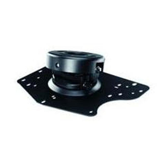
All-in-one Projector Adapter Plate for
WARNING
1 of 11
Model: SP-CEIL-UNIV
Maximum Load Capacity: 25 lb (11 kg)
ISSUED: 10-22-04 SHEET #: 055-9236-5 01-10-06
Advertisement
Table of Contents

Subscribe to Our Youtube Channel
Related Manuals for InFocus SP-CEIL-UNIV


Summary of Contents for InFocus SP-CEIL-UNIV
- Page 1 Installations: To Wood Joist Finished Ceilings, Exposed Wood Joists, or Wood Beam Ceilings ... page 3 To Concrete Ceilings ... page 4 Visit the InFocus Web Site at www.infocus.com All-in-one Projector Adapter Plate for WARNING 1 of 11 Model: SP-CEIL-UNIV...
-
Page 2: Parts List
M6 x 12 mm serrated socket pin screw M4 x 6 mm serrated socket pin screw ceiling plate adapter plate extension bracket Note: Actual parts may appear slightly different than illustrated. Visit the InFocus Web Site at www.infocus.com Qty. Part Number 055-0420 560-9646 520-1151... -
Page 3: Installation To Wood Joist Finished Ceilings, Exposed Wood Joists, Or Wood Beam Ceilings
The use of an "edge to edge" stud finder is highly recommended. Skip to step 7. WOOD JOIST CEILING Visit the InFocus Web Site at www.infocus.com For optional Cord Management, install two spacers (L) between ceiling plate (Q) and ceiling. 3 of 11 CONNECTION BLOCK... -
Page 4: Installation To Concrete Ceilings
CORRECT metal bracket plaster/ dry wall Visit the InFocus Web Site at www.infocus.com Drill hole and insert anchor. Place ceiling plate over anchor and secure with screw. concrete After repeating step one tighten all fasteners. concrete 4 of 11... -
Page 5: Flush Mount Installation
The use of an "edge to edge" stud finder is highly recommended. Skip to step 7. WOOD JOIST figure 1 Visit the InFocus Web Site at www.infocus.com FRONT OF MOUNT 5 of 11 FRONT OF MOUNT... -
Page 6: Installation To Extension Column
Skip to step 7. SWIVEL STOP SCREW DETAIL 5 Visit the InFocus Web Site at www.infocus.com DETAIL 3 SWIVEL STOP SCREW 3/4" EXTENSION COLUMN ACC 913 (NOT UL LISTED) - Page 7 Do not overtighten screws; overtightening screws will damage threads making it difficult to separate the products. Skip to step 7. Visit the InFocus Web Site at www.infocus.com LIGHTWEIGHT SUSPENDED CEILING PLATE (SOLD SEPARATELY) DETAIL 8...
- Page 8 (A) using two #10-32 x 3/8" serrated socket pin screws (C) as shown. FRONT OF PROJECTOR Visit the InFocus Web Site at www.infocus.com CONNECTION BLOCK Attach extension brackets (S) to adapter plate (R) using two M4 x 6 mm serrated socket pin screws (P).
- Page 9 SP7200, SP7205, SP7210 D. C100, C105, DP6150, DP6155, LP690 G. C160, C180, LP540, LP640, SP5000 Visit the InFocus Web Site at www.infocus.com B. C40, C50, DP2000S, DP2000X, LP240, LP250 E. C109, C110, DP8000, LP790, SP4800, SP4805, X1, X1a, X2, X3...
- Page 10 (A) as shown. Tighten captive screw to secure projector to projector mount assembly (A). FRONT OF MOUNT CAPTIVE SCREW Visit the InFocus Web Site at www.infocus.com IN24, IN26 WARNING IMPORTANT: For security installations, insert one #10-32 x 1/4" socket pin screw (D) through projector mount assembly (A) and into connection block as shown.
-
Page 11: Projector Alignment
To adjust roll (side to side tilt): Loosen two screws on projector mount assembly (A) indicated below. Tilt mount to desired position and retighten screws. SCREWS FOR PITCH ADJUSTMENT Visit the InFocus Web Site at www.infocus.com SCREW FOR SWIVEL STOP SCREWS FOR ROLL ADJUSTMENT...
Need help?
Do you have a question about the SP-CEIL-UNIV and is the answer not in the manual?
Questions and answers