Table of Contents
Advertisement
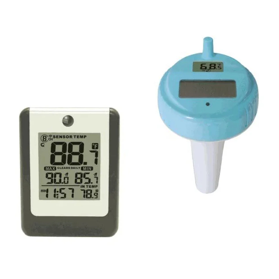
Ambient Weather WS-14 Wireless 8-Channel Floating Pool
and Spa Thermometer with Daily Min/Max Display User
Table of Contents
1
Introduction ..................................................................................................................................... 2
2
Getting Started ................................................................................................................................ 3
2.1 Parts List ....................................................................................................................................... 3
2.2 Floating Pool and Spa Thermometer Sensor Set Up ..................................................................... 3
2.3 Sensor Placement .......................................................................................................................... 8
3
Maintenance .................................................................................................................................... 8
4
Display Console Set Up .................................................................................................................. 9
4.1 Display Console Layout .............................................................................................................. 10
4.2 Sensor Operation Verification ..................................................................................................... 10
5
Display Features ............................................................................................................................ 10
5.1 Rate of Change Icon .................................................................................................................... 10
5.2 Console Operation....................................................................................................................... 11
5.2.1 Set Mode .............................................................................................................................. 11
5.2.2 Viewing the High and Low Alarms ...................................................................................... 11
5.2.3 Alarm Defaults ..................................................................................................................... 11
5.2.4
Setting the Min and Max Alarm ....................................................................................... 11
5.3 Manually Reset Max/Min ........................................................................................................... 12
5.4 Channel Selection ....................................................................................................................... 12
5.5 Sensor Search Mode .................................................................................................................... 12
5.6 Best Practices for Wireless Communication ............................................................................... 12
5.7 Adjustment or Calibration ........................................................................................................... 13
5.7.1 Remote Sensor Temperature Calibration.............................................................................. 13
5.7.2 Indoor (Console) Temperature Calibration .......................................................................... 13
6
Glossary of Terms ......................................................................................................................... 14
7
Specifications ................................................................................................................................ 14
7.1 Wireless Specifications ............................................................................................................... 14
7.2 Measurement Specifications ....................................................................................................... 14
7.3 Power Consumption .................................................................................................................... 14
8
Troubleshooting Guide .................................................................................................................. 15
9
Liability Disclaimer ...................................................................................................................... 16
10
FCC Statement .......................................................................................................................... 16
11
Warranty Information ............................................................................................................... 17
Version 1.1
©Copyright 2014, Ambient LLC. All Rights Reserved.
Manual
Page 1
Advertisement
Table of Contents

Related Manuals for Ambient Weather WS-14


Summary of Contents for Ambient Weather WS-14
-
Page 1: Table Of Contents
Ambient Weather WS-14 Wireless 8-Channel Floating Pool and Spa Thermometer with Daily Min/Max Display User Manual Table of Contents Introduction ............................. 2 Getting Started ..........................3 2.1 Parts List ............................3 2.2 Floating Pool and Spa Thermometer Sensor Set Up ..............3 2.3 Sensor Placement .......................... -
Page 2: Introduction
1 Introduction Thank you for your purchase of the Ambient Weather WS-14 Wireless 8-Channel Floating Pool and Spa Thermometer with Daily Min/Max Display. The following user guide provides step by step instructions for installation, operation and troubleshooting. To download the latest manual and additional troubleshooting tips, please visit the FAQ website: http://ambientweather.wikispaces.com/ws14... -
Page 3: Getting Started
Note: The power up sequence must be performed in the order shown in this section (insert batteries in the remote transmitter(s) first, Display Console second). The WS-14 weather station consists of a display console (receiver), and a thermometer (remote transmitter). - Page 4 1. To insert the batteries,, (1) Twist the KEY lid to unlock, (2) remove the key, and (3) twist the main body of the sensor by removing the lid, as shown in Figure 2 . Figure 2 2. The floating thermometer includes dip switches for assigning channel numbers. BEFORE inserting the batteries, locate the dip switches on the inside cover of the lid of the transmitter.
- Page 5 Channel Number: The F007PF supports up to eight transmitters. To set each channel number (the default is Channel 1), change Dip Switches 1, 2 and 3, as referenced in Table Temperature Units of Measure: To change the transmitter display units of measure (°F vs. °C), change Dip Switch 4, as referenced in Table DIP SWITCH FUNCTION...
- Page 6 4. After inserting the batteries, the remote sensor LED indicator will light for 4 seconds, and then flash once per 60 seconds thereafter. Each time it flashes, the sensor is transmitting data. 5. Verify the correct channel number (CH) and temperature units of measure (°F vs. °C) are on the display, as shown in Figure 5.
- Page 7 7. To close the lid, (1) Twist the lid until it is firmly locked and the key is aligned. (2) Insert the key and turn 90 degrees to lock the lid, as shown in Figure 7. Figure 7 A tether can be added into the key as shown in Figure 8. Figure 8 Place the sensor in the water and make sure that it is within the effective transmission range from the display console.
-
Page 8: Sensor Placement
2.3 Sensor Placement Place the sensor in the pool or spa within 100 feet of the display console (Figure 9, reference A). Avoid transmitting through solid earth or ground (Figure 9, reference B). Use a tether (string) to fix the sensor in the pool or spa. Place the console at least three feet away from computers, TVs and wireless phones. -
Page 9: Display Console Set Up
Silicone grease is available at most hardware and pool stores. 4 Display Console Set Up Move the remote sensor(s) about 5 to 10’ away from the display console (if the sensor is too close, it may not be received by the display console). If you have more than one remote sensor, make sure they are all powered up and transmitting on different channels. -
Page 10: Display Console Layout
will automatically toggle between sensors until all sensors have reported in. Do not touch any buttons until the remote sensor has reported in, or the radio search icon is no longer constantly on, otherwise the remote sensor search mode will be terminated. When the remote sensor temperature has been received, the console will automatically switch to the normal mode, and all further settings can be performed. -
Page 11: Console Operation
5.2 Console Operation Note: The console has three buttons for easy operation: SET button, MIN/MAX button, and CH/+ button. 5.2.1 Set Mode The Set Mode allows you to set the time and time format, time alarm and units of measure. To enter the set mode, press and hold the SET key for 3 seconds. -
Page 12: Manually Reset Max/Min
three seconds to toggle the alarm on and the alarm off. The alarm icon will appear when set, and disappear when disabled. Press (do not hold) the SET button again to set the LOW (min) temperature alarm. The LOW alarm for temperature will flash. -
Page 13: Adjustment Or Calibration
line of sight. The following is a table of reception loss vs. the transmission medium. Each “wall” or obstruction decreases the transmission range by the factor shown below. Medium RF Signal Strength Reduction Glass (untreated) 5-15% Plastics 10-15% Wood 10-40% Brick 10-40% Concrete... -
Page 14: Glossary Of Terms
To return the temperature to the actual or uncalibrated measurement, press the SET button. Once the displayed temperature equals the calibrated source, press and hold the SET button for three seconds, or wait 15 seconds for timeout, and the temperature value will stop flashing. Discussion: Temperature errors can occur when a sensor is placed too close to a heat source (such as a building structure, the ground or trees). -
Page 15: Troubleshooting Guide
8 Troubleshooting Guide If your question is not answered here, you can contact us as follows: 1. Email Support: support@ambientweather.com 2. Live Chat Support: www.ambientweather.com/chat.html (M-F 8am to 4pm Arizona Time) 3. Technical Support: 480-283-1644 (M-F 8am to 4pm Arizona Time) Problem Solution Wireless remote (thermo-hygrometer) not... -
Page 16: Liability Disclaimer
9 Liability Disclaimer Please help in the preservation of the environment and return used batteries to an authorized depot. The electrical and electronic wastes contain hazardous substances. Disposal of electronic waste in wild country and/or in unauthorized grounds strongly damages the environment. Reading the “User manual”... -
Page 17: Warranty Information
11 Warranty Information Ambient, LLC provides a 1-year limited warranty on this product against manufacturing defects in materials and workmanship. This limited warranty begins on the original date of purchase, is valid only on products purchased and only to the original purchaser of this product. To receive warranty service, the purchaser must contact Ambient, LLC for problem determination and service procedures.
Need help?
Do you have a question about the WS-14 and is the answer not in the manual?
Questions and answers